Printronix SL5000r User Manual
Rfid smart label and thermal printers
Hide thumbs
Also See for SL5000r:
- User manual (92 pages) ,
- Reference manual (84 pages) ,
- Quick setup manual (64 pages)
Table of Contents
Advertisement
Quick Links
Advertisement
Chapters
Table of Contents
Troubleshooting

Related Manuals for Printronix SL5000r


Summary of Contents for Printronix SL5000r
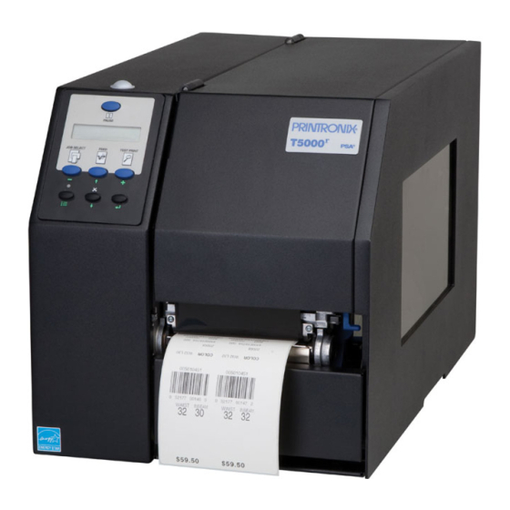
- Page 1 User’s Manual SL5000 and T5000 RFID Smart Label and Thermal Printers...
-
Page 3: Software License Agreement
You accept the terms of this Agreement by your initial use of your printer. 1. Object Code License Printronix grants you a nonexclusive license to use the Printronix Software, the eCos Software and all other embedded software (collectively, the “Embedded Software” or the “Software”) only in conjunction with the printer. - Page 4 You agree that this Agreement provides you no more rights with regards to warranty, support, indemnity or liability terms with respect to Red Hat, Inc., Printronix Inc, or any contributor to the Embedded Software than that provided by the Red Hat eCos Public License v.1.1 or any express warranty that may be made by Printronix, Inc.
-
Page 5: Limited Software Product Warranty
Limited Software Product Warranty Printronix, Inc. warrants that for ninety (90) days after delivery, the Software will perform in accordance with specifications published by Printronix, Inc. Printronix, Inc. does not warrant that the Software is free from all bugs, errors and omissions. Remedy Your exclusive remedy and the sole liability of Printronix, Inc. - Page 6 LIABILITY FOR CONSEQUENTIAL OR INCIDENTAL DAMAGES, SO THE ABOVE LIMITATION MAY NOT APPLY TO YOU. 3. Printronix, Inc. will not be liable for any loss or damage caused by delay in furnishing a Software Product or any other performance under this Agreement.
-
Page 7: Communication Notices
Operating Frequency:869.525 (AWID 869) or 902 to 928 MHz (AWID 915) Typical RF Power: 25 to 100 milliwatts (SL5x04 MP) or 25 to 205 milliwatts (SL5x04 C1) Maximum RF Power: 1 Watt under abnormal conditions Printronix SL5000 and T5000 Tested To Comply With FCC Standards... - Page 8 (e.i.r.p.) is not more than that permitted for successful communication. CE Notice (European Union) Marking by the CE symbol indicates compliance of this Printronix system to the EMC Directive and the Low Voltage Directive of the European Union. Such marking is indicative that this Printronix system meets the following technical standards: •...
-
Page 9: Important Warranty Information
IMPORTANT WARRANTY INFORMATION PRINTER WARRANTY Printronix® warrants to the purchaser that under normal use and service, this printer (excluding the thermal printhead) purchased hereunder shall be free from defects in material and workmanship for a period of one year from the date of shipment from Printronix. -
Page 10: Lithium Battery
Printronix makes no representations or warranties of any kind regarding this material, including, but not limited to, implied warranties of merchantability and fitness for a particular purpose. Printronix shall not be held responsible for errors contained herein or any omissions from this material or for any damages, whether direct, indirect, incidental or consequential, in connection with the furnishing, distribution, performance or use of this material. -
Page 11: Trademark Acknowledgements
Trademark Acknowledgements Printronix, IGP, Auto Label Mapping, LinePrinter Plus, PGL, and PrintNet are registered trademarks of Printronix, Inc. ThermaLine, T5000 , and SL5000 is a trademark of Printronix. HP is a registered trademark of Hewlett-Packard Company. Code V is a trademark of QMS, Inc. -
Page 13: Table Of Contents
1 Introduction ............19 Printronix Customer Support Center............ 19 Printronix Supplies Department............. 19 Corporate Offices ................20 Training Available On Printronix Products ........... 20 Warnings And Special Information ............21 Manual Conventions ................21 The SL5000r/T5000r Series RFID/Label Printer........22 Standard Features ................ - Page 14 Table of Contents Printing Adjustments................64 Printhead Pressure Adjustment ............ 64 Printhead Pressure Block Adjustments ......... 65 Positioning The Media Sensors ............ 66 Sensing Different Media Types ............. 71 Running Auto Calibrate ..............72 Running Media Profile..............74 Running Manual Calibrate............. 79 Cleaning....................
- Page 15 Table of Contents SPC COAX SETUP ................167 SPC TWINAX SETUP ............... 168 IPDS SETUP ..................169 TN3270 SETUP ................. 173 TN5250 SETUP ................. 175 IGP/PGL SETUP ................177 IGP/VGL SETUP ................179 P-SERIES SETUP ................181 P-SER XQ SETUP................183 SERIAL MATRIX SETUP ..............
- Page 16 Downloading Software If Flash Contains Only Boot Or Corrupt Code ....................287 Using TrueType Fonts ............... 289 Downloading TrueType Fonts............289 Printronix Windows Driver ............290 PGL Emulation (Online) .............. 290 Download Mode ................291 PTX_SETUP ................293 Labeling Applications ..............293 Select And Print Downloaded TrueType Fonts........
- Page 17 B Printer Options ..........355 Hardware Options................355 Interface Options ................. 356 Supplies And Accessories ..............358 Genuine Printronix Thermal Transfer Ribbons......358 Genuine Printronix Media............359 Accessories ................. 361 C ASCII Control Codes......... 363 D Media Cutter Installation ........365 Prepare The Printer ................
- Page 18 Table of Contents E Media Cutter Tray Installation ......369 Assembling The Media Cutter Tray ........... 369 Installing The Media Cutter Tray............370 F Glossary ............373...
-
Page 19: Introduction
Europe, Middle East, and Africa (31) 24 6489 311 Asia Pacific (65) 6548 4114 http://www.printronix.com/support.aspx Printronix Supplies Department Contact the Printronix Supplies Department for genuine Printronix supplies. Americas (800) 733-1900 Europe, Middle East, and Africa (33) 1 46 25 1900 Asia Pacific... -
Page 20: Corporate Offices
Visit the Printronix web site at www.printronix.com Training Available On Printronix Products Printronix offers Product Maintenance Training Classes designed to enhance the knowledge of your service personnel. Led by Printronix’ staff of highly trained, experienced instructors, these structured classes include: •... -
Page 21: Warnings And Special Information
Warnings And Special Information Corporate Offices Warnings And Special Information For your safety and to protect valuable equipment, read and comply with all information highlighted under special headings: WARNING Conditions that could harm you and damage the equipment. WARNING Achten Sie auf folgendes, um keine Personen in Gefahr zu bringen bzw. das Gerät zu beschädigen. -
Page 22: The Sl5000R/T5000R Series Rfid/Label Printer
Chapter The SL5000r/T5000r Series RFID/Label Printer The SL5000r/T5000r Series RFID/Label Printer NOTE: As used in this manual, the terms “T5000r” and “printer” refer to all models within the series. “SL” refers to all SmartLine RFID models. The T5000r series consists of a family of high quality, direct thermal and thermal transfer printers specifically designed for printing labels and tags from ®... -
Page 23: Standard Features
), and ® PPI/DGL (Datamax ) interpreters are powerful integration tools that allow the SL5000r/T5000r to function in virtually all legacy ZPL, TEC, IPL, SATO, and DPL™ application environments without requiring modification to host data stream. • Thermal Transfer and Direct Thermal Printing: On all printers (except DT models, which print only in thermal mode). -
Page 24: Optional Features
Chapter The SL5000r/T5000r Series RFID/Label Printer ® • Auto Label Mapping : For compatibility with programs written for Printronix line matrix printers. • Ventless System: For operation in environments with airborne particulate matter without compromising performance. Optional Features Ask your authorized representative about the following enhancement options: •... -
Page 25: Thermal Printer Technology
• RFID Encoder: The RFID (Radio Frequency Identification) encoder reads and writes information to smart labels (with embedded RFID tags). NOTE: The RFID encoder is standard on the SL5000r, and optional for the T5000r. • RS-422: Serial interface option. -
Page 26: Dynamic Print Control
Most of these media options can be die-cut for easy label applications. The wide selection of media sizes and face stocks have been tested with Printronix ribbons for print quality and usage. Consult your Genuine Printronix Supplies Catalog, call the Printronix Customer Solutions Center at (714) 368-2686, or access the Printronix web page at www.printronix.com. -
Page 27: Setting Up The Printer
Unpacking The Printer Setting Up The Printer Unpacking The Printer The printer is shipped in a carton and protective bag. The top lid of the carton has instructions for removing the internal packing material. Keep all packing material in case repacking is required. CAUTION Avoid touching the electrical connectors to prevent electrostatic discharge damage while setting up the printer. - Page 28 Chapter Setting Up The Printer Foam 4. Remove the foam pad between the pivoting deck and the frame. Pivoting Deck Platen Deck Lock Lever Printhead Foam Pad 5. Open the pivoting deck by rotating the blue deck lock lever fully clockwise.
-
Page 29: Installation
Installation Installation The following sections will guide you through the printer installation process. 1. Place the printer on a flat level surface that allows easy access to all sides of the printer. CAUTION Never operate the printer while it is resting on its side or upside down. 2. - Page 30 Chapter Setting Up The Printer 5. Attach Interface: a. Parallel Interface Attach a suitable parallel printer cable from the computer to the Centronics/IEEE 1284 interface connector at the back of the printer. Snap the bail locks to the Centronics connector to secure the interface cable to the printer.
- Page 31 Installation NOTE: The software turns on the amber status LED at power-up. If a hardware problem is detected at power-up the amber LED will blink continuously. The hardware turns on the green LED at power-up. If a problem is detected with the software stored in the printer’s flash memory both the amber and green LEDs will alternately blink continuously.
- Page 32 Chapter Setting Up The Printer If your printer is equipped with the optional Wireless and Optional GPIO it will appear as illustrated below. Wireless And GPIO Interface Panel Wireless Antenna Wireless Interface GPIO Connection c. Coax Connection Attach a suitable coaxial cable from the computer to the coax connector located in the I/O plate in the back of the printer.
-
Page 33: Operation
Operation Controls And Indicators Power Switch The power switch is located on the bottom back panel of the printer. To apply power, place the switch in the | (ON) position. When you first power on the printer, a series of initialization messages will appear on the Liquid Crystal Display (LCD) on the control panel. - Page 34 Chapter Controls And Indicators Status and Display Indicators...
- Page 35 Control Panel Control Panel Keys...
- Page 36 Chapter Controls And Indicators Control Panel Keys (cont.)
-
Page 37: Powering On The Printer
Powering On The Printer Powering On The Printer When you power on the printer, it executes a self-test. During the self-test, the LCD momentarily displays the DPI resolution (203 or 300 DPI) of the installed printhead. The default power-on state is online. Once the printer has successfully initialized, the ONLINE status indicator light illuminates, and the LCD indicates the communication interface selected and the type of emulation installed. -
Page 38: Loading Media And Ribbon
Chapter Loading Media And Ribbon • Peel-Off. When the optional internal rewinder is installed, the printer prints and peels die-cut labels from the liner without user assistance. The label liner is wound on the rewinder. The printer waits for you to take away the label before printing the next one (on-demand printing). -
Page 39: Loading Roll Media
Loading Roll Media Loading Roll Media Media Cover Media Hanger Media Hanger Guide Pivoting Deck Media Width Guide Media Damper Deck Lock Lever 1. Open the media cover. 2. Slide the blue media hanger guide outward to the end of the media hanger, and flip it up horizontally. - Page 40 Chapter Loading Media And Ribbon Media Roll Media Hanger Media Hanger Guide 5. Slide a roll of media onto and towards the back of the media hanger. The media feeds from the top of the roll and towards the front of the printer. 6.
- Page 41 Loading Roll Media Media and Ribbon Loading Instruction Media Printhead Media Damper Platen (Rubber Drive Roller) 7. Thread the media under the media damper and then between the platen (rubber drive roller) and the printhead. You can also refer to the arrows on the printer frame or to the label inside the media cover for media loading instructions.
- Page 42 Chapter Loading Media And Ribbon Lower Media Sensor Media Guard Fixed Guide Media Width Guide Media Sensor Handle Media Damper 8. Verify that the left (inside) edge of the media is against the fixed guide on the bottom of the media damper. 9.
- Page 43 Loading Roll Media Upper Sensor Visible Red Beam Lower Sensor Upper Sensor Handle Media Guard Opening 11. Slide the upper sensor directly over the lower sensor. Media (left edge) Guide Notch 12. Align the left (inside) edge of the media with the guide notch located on the front edge of the tear bar.
- Page 44 Chapter Loading Media And Ribbon Pivoting Deck Deck Lock Lever 13. Close the pivoting deck and rotate the deck lock lever fully counterclockwise. This locks the pivoting deck and printhead assembly into the printing position. IMPORTANT Ensure the pivoting deck is down and locked before attempting to advance media or print.
- Page 45 Loading Roll Media For direct thermal operation (no ribbon required): • If you have not run an Auto Calibrate, do so now. See “Running Auto Calibrate” on page 72. • If you have already run an Auto Calibrate, complete the following steps: a.
-
Page 46: Loading Fanfold Media
Chapter Loading Media And Ribbon Loading Fanfold Media Fanfold Media Cover Tension Fanfold Media Media Hanger Pivoting Guide Deck Media Hanger Bottom Panel Opening Deck Lock Lever 1. Open the media cover. 2. Slide the media hanger guide outward to the end of the media hanger and rotate it upward to a horizontal position to remove any roll media. - Page 47 Loading Fanfold Media Media Sensor Media Guard Fixed Guide Media Width Guide Media Sensor Handle Media Damper 8. Slide the media width guide outward to the end of the media damper. 9. Thread the media under the media damper and then between the platen (rubber drive roller) and the printhead.
- Page 48 Chapter Loading Media And Ribbon Media (left edge) Guide Notch 12. Align the left (inside) edge of the media with the guide notch located on the front edge of the tear bar.
- Page 49 Loading Fanfold Media Pivoting Deck Deck Lock Lever 13. Close the pivoting deck and rotate the deck lock lever fully counterclockwise. This locks the pivoting deck and printhead assembly into the printing position. IMPORTANT Ensure the pivoting deck is down and locked before attempting to advance media or print.
- Page 50 Chapter Loading Media And Ribbon For direct thermal operation (no ribbon required): • If you have not run an Auto Calibrate, do so now. See “Running Auto Calibrate” on page 72. • If you have already run an Auto Calibrate, complete the following steps: a.
-
Page 51: Loading Ribbon
Loading Ribbon Loading Ribbon Skip this section for 4 inch DT models or when using direct thermal printing. Ribbon Take-Up Core Ribbon Take-up Spindle Pivoting Deck Ribbon Supply Spindle Ribbon Roll Deck Lock Lever 1. Install the ribbon take-up core on the ribbon take-up spindle. NOTE: The first ribbon take-up core comes with the printer. - Page 52 Chapter Loading Media And Ribbon Ribbon Printhead Media Rear Ribbon Guide Roller 4. Thread the end of the ribbon under the rear ribbon guide roller, then between the platen and the printhead. You can also refer to the arrows on the printer frame or to the upper-right corner of the label inside the media cover for ribbon loading instructions.
- Page 53 Loading Ribbon Media Cover Media and Ribbon Loading Instructions Ribbon Take-up Core Ribbon Take-up Spindle IMPORTANT Do not attach the ribbon to the ribbon take-up spindle without a fiberboard take-up core installed. 5. Attach the ribbon to the ribbon take-up core on the ribbon take-up spindle using the adhesive on the ribbon leader.
-
Page 54: Using The Optional Internal Rewinder
Chapter Using The Optional Internal Rewinder 9. If you have not run an Auto Calibrate with this media and ribbon, do so now. See “Running Auto Calibrate” on page 72. 10. Press the FEED key once to verify that the media and ribbon advance. 11. - Page 55 Batch Rewind Mode Installing The Media Guide The media guide must be installed when using Batch Rewind mode. Front Door Media Guide Hook Groove To install the media guide: 1. Open the front door by pulling it upwards, then forward. 2.
- Page 56 Chapter Using The Optional Internal Rewinder Loading Media Rewinder Release Lever Rewinder 1. To load media, refer to “Loading Roll Media” on page 39 and complete steps 1 through 10.
- Page 57 Batch Rewind Mode Media Media Guide Rewinder Release Lever Slot 2. Thread the media over the front of the media guide and through the opening under the front door toward the internal rewinder. IMPORTANT If you do not complete the following step, it will be extremely difficult to remove the printed labels from the rewinder.
- Page 58 Chapter Using The Optional Internal Rewinder Media Cover Deck Lock Lever 6. Press down on both sides of the pivoting deck and rotate the deck lock lever counterclockwise against its stop to place the printhead assembly into the printing position. 7.
- Page 59 Batch Rewind Mode Removing Printed Media from the Rewinder Release Lever Rewinder Printhead 1. Open the media cover. 2. Press the FEED key to advance the last printed label past the printhead, and tear the liner from behind the last printed label. 3.
-
Page 60: Label Peel-Off
Chapter Using The Optional Internal Rewinder Label Peel-Off You can set up the printer to automatically peel die-cut labels off their liner (backing) and dispense them one at a time while rewinding the liner. You can install the media guide to prevent long labels from accidentally adhering to the front door assembly, but it is normally not needed when using labels less than two inches long (see “Installing The Media Guide”... - Page 61 Label Peel-Off Back Flange Raised Ridge Rewinder Release Lever Slot Liner IMPORTANT If you do not complete the following step, it will be difficult to remove the liner from the rewinder. 6. Turn the release lever on the rewinder counterclockwise and lock it in place.
- Page 62 Chapter Using The Optional Internal Rewinder Media Cover Deck Lock Lever 12. Press down on both sides of the pivoting deck and rotate the deck lock lever fully counterclockwise. 13. Press the FEED key. The label advances to the peel-off position, and “Remove Label”...
-
Page 63: Removing The Media Guide
Removing The Media Guide Removing Label Liner from the Rewinder 1. Open the media cover. 2. Open the front door. 3. Tear the liner at the tear bar. 4. Manually rewind the remaining liner onto the rewinder by turning the rewinder counterclockwise. -
Page 64: Printing Adjustments
Chapter Printing Adjustments Printing Adjustments Printhead Pressure Adjustment Printhead Pressure Adjustment Dial Active Pressure Setting Sometimes you will need to adjust printhead pressure because of variations in media thickness and width. The printhead pressure adjustment dial is shown above. The value shown at the bottom of the dial is the active setting. In general, adjust printhead pressure to the lowest value which produces the desired print quality. -
Page 65: Printhead Pressure Block Adjustments
Printhead Pressure Block Adjustments Printhead Pressure Block Adjustments Right Pressure Block Right Pressure Block Pointer Left Pressure Block Lead Screw Knob Pressure Block Adjustment Scale Left Pressure Block Handle Printhead pressure block adjustments are used to obtain a uniform print density across the width of the installed media under a variety of media and ribbon conditions. -
Page 66: Positioning The Media Sensors
Chapter Printing Adjustments 3. Press the ↵ key to start the Grey test pattern. The pattern will start and continue to print. 4. Press ↵ again to stop printing. 5. Check the test pattern. If necessary reposition the pressure blocks to obtain a uniform print density across the media width. - Page 67 Positioning The Media Sensors Sensing Media with Horizontal Black Marks (Mark) or Media with No Label Length Indicators (Disable) Visible Red Beam from Lower Sensor Lower Sensor Black Mark (underside of media) Sensor Handle Media Guard Opening Sensing Media with Horizontal Black Marks Position the lower media sensor for detecting horizontal black marks located on the underside of media, and position the upper sensor above the lower sensor to provide a consistent background.
- Page 68 Place the upper sensor above the lower sensor to provide a consistent background. NOTE: The 4 inch SL5000r/T5000r media guard is divided into three open sensor areas. Make sure the media sensor is placed in an open area.
- Page 69 Positioning The Media Sensors Sensing Media with Dark Background Labels with Gaps (Advanced Gap) Upper Sensor Visible Red Beam Lower Sensor Upper Sensor Handle Media Guard Opening NOTE: Ribbon is not displayed in this illustration. The upper and lower sensors are designed to function with or without ribbon installed. The upper sensor and lower sensor are used together to detect liner gaps between die cut labels that have a black or dark background on white or clear liner.
- Page 70 Chapter Printing Adjustments Sensing Dark Background Media with Notches or Holes (Advanced Notch) Upper Sensor Upper Sensor Handle Visible Red Beam Lower Sensor Black line on underside of media Media Guard Opening NOTE: Ribbon is not displayed in this illustration. The upper and lower sensors are designed to function with or without ribbon installed.
-
Page 71: Sensing Different Media Types
Sensing Different Media Types Sensing Different Media Types The printer’s media sensors can detect the different types of label length indicators on a large variety of media types. This is accomplished by selecting the correct sensor option: Gap, Mark, Advanced Gap, Advanced Notch, or Disable under Gap/Mark Sensor in the CALIBRATE CTRL menu. -
Page 72: Running Auto Calibrate
Chapter Printing Adjustments Calibrating The Media Sensors Due to manufacturing differences in media and ribbon, the media sensors may have difficulty differentiating between the label and the liner or the label and the black mark. When this occurs, the printer may intermittently skip a label or display a fault message such as “GAP NOT DETECTED/See Manual”... - Page 73 Running Auto Calibrate 1. Press the PAUSE key until “OFFLINE” appears on the LCD. 2. Press ↓ and ↵ together until “ENTER SWITCH UNLOCKED” displays. 3. Press the TEST PRINT key until “Printer Tests/Auto Calibrate” displays. ↵ 4. Press . Media advances until it can accurately detect the label length indicators and then stops at the Top-of-Form position.
-
Page 74: Running Media Profile
Chapter Printing Adjustments Running Media Profile The Media Profile printout shows the relationship of the Paper Out Threshold and the Gap/Mark Threshold values, illustrates if and when each label length indicator is detected, and shows the difference between the label length indicators and the label. -
Page 75: Gap Sensing
Running Media Profile Paper Out(144) Gap Mark(105) Figure 1. Media Profile Printout Gap Sensing This figure shows a Media Profile printout of a smart label where Gap/Mark Sensor is set to Gap in the CALIBRATE CTRL menu. In this example, the gap threshold value the printer selected (represented by the Gap/Mark dotted line) is too close to the amplitude of the antenna pulse. - Page 76 Chapter Printing Adjustments To avoid this problem, increase the Threshold Range value to 60% or 70% in the CALIBRATE CTRL menu (the default is 50%), then run an Auto Calibrate again (Cross-Ref to Auto Calibrate). NOTE: Any changes to Threshold Range will not take effect until you run an Auto Calibrate again.
- Page 77 Running Media Profile Advanced Gap Sensing This figure shows a Media Profile printout of a smart label where Gap/Mark Sensor is set to Advanced Gap in the CALIBRATE CTRL menu. In this example, the gap threshold value the printer selected (represented by the Gap/Mark dotted line) is too close to the amplitude of the antenna pulse.
- Page 78 Chapter Printing Adjustments To avoid this problem, increase the Threshold Range value to 60% in the CALIBRATE CTRL menu (the default is 50%), then run an Auto Calibrate again (Cross-ref to Auto Calibrate). NOTE: Any changes to Threshold Range will not take effect until you run an Auto Calibrate again.
-
Page 79: Running Manual Calibrate
Running Manual Calibrate Running Manual Calibrate Manual Calibrate should be performed only when the values derived from Auto Calibrate fail to improve the media sensors’ ability to sense label length indicators on the installed media. You must first enable “Admin User” in the PRINTER CONTROL menu before accessing or initializing Manual Calibrate in the CALIBRATE CTRL menu. -
Page 80: Cleaning
Chapter Cleaning 11. Press the FEED key several times. Each time you press FEED, the media advances one label length and stops. NOTE: After a form feed, the position of the leading edge of the next label depends on the type of Media Handling mode selected under the QUICK SETUP menu. -
Page 81: Platen Roller Cleaning
Cleaning The Printhead, Platen Roller And Media Sensors Platen Roller Cleaning Media dust and adhesive residue on the platen roller can degrade print quality and cause voids in your label image. Clean the platen roller at the same time as the printhead. Use a small amount of isopropyl alcohol on the cloth or the cleaning pen supplied with your printer to clean the platen roller. - Page 82 Chapter Cleaning Printhead Pivoting Heating Deck Elements Peel/Tear Door Lower Media Sensor (visible with red LED) Printhead Cover/ Upper Media Sensor Deck Lock Lever Platen Roller Print Element Upper Sensor...
- Page 83 Cleaning The Printhead, Platen Roller And Media Sensors 1. Rotate the deck lock lever clockwise to open the pivoting deck and remove any media and ribbon (if loaded) to gain access to the printhead assembly heating element area. 2. Gently rub the felt tip of the cleaning pen or a cotton swab with Isopropyl alcohol across the printhead heating elements (light brown area).
- Page 84 Chapter Cleaning...
-
Page 85: Configuring The Printer
Configuring The Printer Overview This chapter provides information about: • Setting, saving, modifying, and printing configurations • Configuration menus • Downloading emulation and operating system software Setting Printer Configuration Parameters Configuration parameters are set from the control panel or are retrieved from the printer’s memory. -
Page 86: Selecting A Menu Option
Chapter Overview NOTE: In menus with numeric ranges of more than 50 numbers, hold down the + or − key for more than 2 seconds to move through the range in increments of 5. To move in increments of 1 again, release your hold on the + or −... -
Page 87: Changing Printer Settings
Changing Printer Settings IMPORTANT This change takes effect for all subsequent data and operations for the printer as soon as the ↵ key is pressed and the asterisk (*) is displayed. The configuration change(s) stay in effect only while the printer is powered on. -
Page 88: Saving A Configuration
Chapter Overview or − key to scroll 3. When the desired submenu displays, press the through the values or options. 4. Press the ↵ key to select a value. An asterisk (*) displays next to the selected value or option. 5. -
Page 89: Auto Save Configuration
Auto Save Configuration NOTE: If the configuration number has been previously saved and Protect Configs. = Enabled under CONFIG CONTROL, the following error message displays: CONFIG. EXISTS Delete First If the above occurs, see “Modifying A Saved Configuration” on page 91, step 4. -
Page 90: Specifying A Power-Up Configuration
Chapter Overview Specifying A Power-Up Configuration You can specify any one of the nine configurations (1-8 or Factory) as the power-up configuration: 1. Press the key until the following message displays: MENU MODE CONFIG. CONTROL 2. Press the ↓ key until the following message displays: Power-Up Config. -
Page 91: Modifying A Saved Configuration
Modifying A Saved Configuration Modifying A Saved Configuration You can change a saved configuration by rewriting over it. For example, you can modify Config. 1, shown below. Suppose you want to keep all the settings but you want to select the parallel Centronics interface instead of the IEEE 1284 interface. - Page 92 Chapter Overview 4. Before saving the modified configuration, you must delete the original configuration if the Protect Configs. option is enabled. a. Press the ↑ or ↓ key until the following message displays: Delete Config. or − key to cycle through the options (1-8). When the b.
-
Page 93: Printing A Configuration
Printing A Configuration Printing A Configuration We recommend that you print and store your configurations for future reference. The printout provides a list of the parameters that were set when you configured the printer. To print a configuration: 1. Press the key until the following message displays: MENU MODE CONFIG. -
Page 94: Menu Overview
Chapter Menu Overview Menu Overview QUICK RFID VALIDATOR CONFIG. MEDIA SETUP CONTROL CONTROL CONTROL Set the basic RFID encoder Online data Name, store, and Control various menus needed to setup and status validator setup retrieve up to parameters configure the reporting. -
Page 95: Main Menu
Main Menu Loading A Saved Configuration Main Menu QUICK RFID VALIDATOR CONFIG. SETUP CONTROL CONTROL (page 106) (page 115) Print Intensity Refer to the RFID Load Config. Refer to the Online Print Speed Save Config. Labeling Reference Data Validator Print Mode Print Config. - Page 96 Chapter Main Menu MEDIA CALIBRATE PRINTER CONTROL CTRL CONTROL (page 118) (page 138) (page 146) Print Intensity Gap/Mark Sensor SMT: Status Print File List Print Speed Auto Calibrate PAA: Select Tool Auto Locking Print Mode Media Profile LP+ Emulation Set Lock Key Media Handling Sensed Distance CTHI Emulation...
- Page 97 Main Menu Loading A Saved Configuration TWINAX SPC COAX SPC TWINAX COAX 2, 3, 7 2, 3, 4 2, 3, 4 2, 3, 7 SETUP SETUP SETUP SETUP (page 165) (page 167) (page 168) (page 162) Primary Sets Primary Sets SPC Type SPC Type Translation Tbl...
- Page 98 Chapter Main Menu IGP/PGL IPDS SETUP 3270 SETUP 5250 SETUP SETUP (page 177) (page 169) (page 173) (page 175) Character Group Default Font Primary Sets Primary Sets Standard Sets Default Code Pag Translation Tbl Translation Tbl Select LPI Code Page Subset Active Char Set Active Char Set Define CR Code...
- Page 99 Main Menu Loading A Saved Configuration PPI/ZGL PPI/TGL PPI/IGL IGP/VGL SETUP SETUP SETUP SETUP (page 179) SFCC Refer to the Printer Refer to the Printer Refer to the Printer Power-up ^X Protocol Interpreter Protocol Interpreter Protocol Interpreter ™ ™ ™ Power-up ^F (PPI) ZGL (PPI) TGL...
- Page 100 Chapter Main Menu PPI/STGL PPI/DGL P-SERIES P-SERIES XQ 1, 6 1, 6 SETUP SETUP SETUP SETUP (page 181) (page 183) Refer to the Printer Refer to the Printer Select CPI Select CPI Select LPI Select LPI Protocol Interpreter Protocol Interpreter ™...
- Page 101 Main Menu Loading A Saved Configuration SER MATRIX PROPRINTER EPSON FX DIAGNOSTICS 1, 2 1, 2 1, 2, 3 SETUP SETUP SETUP (page 185) (page 187) (page 189) (page 238) Select CPI Select CPI Printer Tests Select CPI Select LPI Select LPI Test Count Select LPI...
- Page 102 Chapter Main Menu USB PORT PARALLEL SERIAL C/T PORT PORT PORT (page 255) (page 242) (page 246) (page 254) Port Type Port Type Port Type Buffer Size in K Data Bit 8 Baud Rate Device Address Timeout PI Ignored Word Length Timeout Buffer Size in K Stop Bits...
- Page 103 Main Menu Loading A Saved Configuration WLAN ETHERNET ETHERNET ETHERNET ADDRESS PORT ADDRESS PARAMS (page 262) (page 256) (page 257) (page 259) IP Address SEG1: NetBIOS Protocol IP Address SEG1: Timeout IP Address SEG2: ASCII Data Port IP Address SEG2: Switch Out On IP Address SEG3: IPDS Data Port...
- Page 104 Chapter Main Menu WLAN KERBEROS WLAN PARAMS PARAMS LEAP (page 264) (page 270) (page 273) Kerberos Enable Auth Method Signal Strength WEP Key 3 BYTE1: Kerb. Pwd(01-15) LEAP Username Operation Mode WEP Key 3 BYTE2: Kerb. Pwd(16-30) Reset LEAP User SSID Name(01-15) WEP Key 3 BYTE3: Kerb.
- Page 105 Main Menu Loading A Saved Configuration BATTERY PRINTER DATE GPIO CONTROL MGMT (page 278) CONTROL (page 274) (page 277) Battery Monitor PNE Port Time/Date Refer to the GPIO Time To Go Mgmt Protocol User’s Guide . Percent Charge PNE Port Number Current Draw PNE Port Timeout Voltage...
-
Page 106: Quick Setup
Chapter QUICK SETUP QUICK SETUP QUICK SETUP (from page 95) Print Print Print Media Paper Feed Label Intensity Speed Mode Handling Shift Length 2, 4 6 ips* Transfer* Tear-Off Strip* 0.00 inches* 4 or 6 inches* -15 to 15 1 ips to 10 ips -0.50 to X inches Direct Tear-Off... -
Page 107: Quick Setup Submenus
QUICK SETUP Submenus QUICK SETUP Submenus Print Intensity This option specifies the level of thermal energy from the printhead to be used for the type of media and ribbon installed. Large numbers imply more heat (thermal energy) to be applied for each dot. This has a significant effect on print quality. - Page 108 Chapter QUICK SETUP • Cut. When the optional media cutter is installed, it automatically cuts media after each label is printed or after a specified number of labels have been printed when a software cut command has been issued. It cuts continuous roll paper, labels, or tag stock.
- Page 109 QUICK SETUP Submenus • Logical Label Length (Host Forms Length) is the length that a user or programmer bases his printable image on. In most cases this length should be slightly less than the Physical Label Length. This allows the entire image to be printed within the boundaries of the label length indicators (gaps, notches, holes, or black marks).
- Page 110 Chapter QUICK SETUP Ver Image Shift This option specifies the amount to shift an image vertically up (-) or down (+) for precise positioning on the label. The actual height of the image is not affected by this parameter. The allowable range is -1.00 inches to the current Label Length value setting, up to a maximum of 12.80 inches, in .01 inch increments.
- Page 111 QUICK SETUP Submenus 4 inches FEED 6 inches Leading Edge • Inv. Portrait. Inverse Portrait refers to vertical page orientation, where the height of a page is greater than its width. The top edge of the image is parallel to the trailing edge of the media. The following illustration is an example, with the operator viewing the front of the printer.
- Page 112 Chapter QUICK SETUP 4 inches FEED 6 inches Leading Edge Gap/Mark Sensor The available options specify the sensor type needed for detecting the Top-of- Form position on media with label length indicators (gaps, notches, holes, or black marks). • Disable. Select when using media with no label length indicators (no gaps, notches, holes, or black marks), or when you want the printer to ignore all existing label length indicators on the installed media.
- Page 113 QUICK SETUP Submenus Auto Calibrate This feature is used to improve the sensitivity and reliability of the Media Sensor in detecting gaps, notches, holes, or black marks on the installed media, as well as a paper out condition. Auto Calibrate can also be initiated from the TEST PRINT key, the ↵...
- Page 114 Chapter QUICK SETUP Save Config. This option allows you to save up to eight unique configurations to meet different print job requirements. This eliminates the need to change the parameter settings for each new job. The configurations are stored in memory and will not be lost if you turn off the printer.
-
Page 115: Config. Control
CONFIG. CONTROL QUICK SETUP Submenus CONFIG. CONTROL CONFIG. CONTROL (from page 95) Load Save Print Delete Power-Up Protect Config. Config. Config Config. Config. Configs. Factory* Current* Factory* Disable* 1 to 8 1 to 8 Factory 1 to 8 1 to 8 Enable Power-Up 1 to 8... -
Page 116: Config. Control Submenus
Chapter CONFIG. CONTROL CONFIG. CONTROL Submenus Load Config. The printer can store up to eight configurations in memory. This parameter allows you to select and load a specific configuration. The factory default is Factory. Save Config. This option allows you to save up to eight unique configurations to meet different print job requirements. - Page 117 CONFIG. CONTROL Submenus Name Config (1-8) You may specify a 15-character name which can be used to refer to a configuration. The name you enter for a configuration will be used in the Load Config., Save Config., Print Config., Delete Config., and Power-Up Config. menus.
-
Page 118: Media Control
Chapter MEDIA CONTROL MEDIA CONTROL MEDIA CONTROL (from page 96) Print Print Print Media Paper Feed Label Intensity Speed Mode Handling Shift Length 2, 4 6 ips* Transfer* Tear-Off Strip* 0.00 inches* 4 or 6 inches* -15 to 15 1 to 10 ips Direct Tear-Off -0.50 to X inches... -
Page 119: Media Control Submenus
MEDIA CONTROL Submenus MEDIA CONTROL (from page 118) Peel-Off Continuous TOF Detect Ticket Save TOF Adjust Mode Mode Fault Mode Mode Fast* Standard* 3 Labels* Disable* Disable* Standard Tear-Off 9 Labels Enable Enable Tear-Strip Full 1 Label Cut Strip TOF Adjust Ribbon Label, 4, 5... - Page 120 Chapter MEDIA CONTROL Print Speed This option specifies the speed in inches per second (ips) at which the media passes through the printer while printing. The range is from 1 to 10 ips (in increments of 1 ips). The factory default is 6 ips. NOTE: The maximum print speed varies based on maximum printer width and dot per inch (dpi) resolution of the printhead installed (203 or 300 dpi).
- Page 121 MEDIA CONTROL Submenus Paper Feed Shift This option represents the distance to advance (+ shift) or pull back (– shift) the stop position of a label when Tear-Off Strip, Tear-Off, Peel-Off, or Cut media handling option is enabled. The allowable range is -0.50 inches to the current Label Length value setting, up to a maximum of 12.80 inches, in .01 inch increments.
- Page 122 Chapter MEDIA CONTROL When the Logical Label Length is greater than the Physical Label Length and Clip Page = Disable, the printer will continue to print the image onto the next physical label and ignore the gap or mark based on the label length value set in the MEDIA CONTROL menu.
- Page 123 MEDIA CONTROL Submenus Hor Image Shift This option specifies the amount to shift an image horizontally left (-) or right (+) for precise positioning on the label. The actual width of the image is not affected by this parameter. The allowable range is -1.00 through +1.00 inches in .01 inch increments.
- Page 124 Chapter MEDIA CONTROL • Landscape. Landscape refers to horizontal orientation, where the width of a page is greater than its height. The top edge of the image is the left edge of the media. The following illustration is an example, with the operator viewing the front of the printer.
- Page 125 The IGP/Auto Label Mapping feature allows backward compatibility of programs written for P5000 line-matrix printers using the Printronix PGL graphics language. It allows the printer to print two-up (or other multi-up) labels. Instead of printing multiple labels across the printer, it prints the leftmost label and the rightmost label, so the printout will be twice as long but half as wide.
- Page 126 Chapter MEDIA CONTROL Examples All of the examples below assume that the logical form length is set to the label length. Example 1: Simple Case Problem: A file has been constructed with two horizontally adjacent 4” labels for a printer with a physical width of 8”. The user now wants to use this file with a printer that has a 4”...
- Page 127 MEDIA CONTROL Submenus Example 2: Uneven Number Case Problem: A file has been constructed with three horizontally adjacent 2” labels. The user now desires to use this file with a printer that has a 4” physical width. Solution #1: The user sets Auto Label Width to 4” (the width of two labels), configures the Num Auto Labels to 2, and enables the Auto Label Mapping feature.
- Page 128 Chapter MEDIA CONTROL Example 3: Past Maximum File Width Problem: A file has been constructed with three horizontally adjacent 4” labels. The user now desires to use this file with a printer that has a 8” physical width. The user should have used a solution similar to one of the solutions in the section above, but the user erroneously enters an Auto Label Width of 12”...
- Page 129 MEDIA CONTROL Submenus Num Auto Labels The desired number of labels to be printed vertically adjacent on the form. The value is selectable with a range of 2 through 40 (T5X04), 2 through 21 (T5X06) and 2 through 17 (T5X08). The factory default is 2.
- Page 130 Chapter MEDIA CONTROL Print Direction and Orientation are two independent options that can be combined to produce the following results depending on the Active IGP Emulation: Table 4. Head First Print Direction Result in Active IGP Emulations Orientation Option Option (IGP/PGL or IGP/VGL) Head First Portrait...
- Page 131 MEDIA CONTROL Submenus Pre-Peel Mode • Disable. • Enable. When Media Handling = Peel-Off and Peel-Off Mode = Standard, enabling Pre-Peel Mode adds a forward and reverse motion to each label prior to printing. The added forward pre-peel motion temporarily breaks the die cut label from the liner, and the reverse motion places the label back on the liner prior to printing, peeling, or dispensing the label.
- Page 132 Chapter MEDIA CONTROL The media sensor looks for the gap, notch, hole, or black mark only after the media has advanced the distance specified by the Label Length value in the MEDIA CONTROL menu or by the Host Forms Length value sent via the software.
- Page 133 MEDIA CONTROL Submenus Ribbon Width When Same As Paper is selected, the printer automatically adjusts the ribbon operating parameters to match the installed media width. In those cases where the media width is less than the installed ribbon width, the Set In Menu option should be selected.
- Page 134 Chapter MEDIA CONTROL Set Label Length This feature selects whether the Sensed Distance value derived from an Auto or Manual Calibrate will be used to set the Label Length value in the MEDIA CONTROL menu (and the QUICK SETUP menu). •...
- Page 135 MEDIA CONTROL Submenus Peel-Off Mode When Peel-Off Media Handling mode (see page 120) is enabled, this feature allows selection of two different media motions for automatic label peel-off. • Fast. Reverse and forward media motion distance in Peel-Off mode is reduced, providing faster throughput.
- Page 136 Chapter MEDIA CONTROL TOF Detect Fault Allows selection of three different TOF (Top-of-Form) detection faults. NOTE: The correct Label Length value, equal to the physical length of the installed label, must be entered in the QUICK SETUP or MEDIA CONTROL menu. •...
- Page 137 MEDIA CONTROL Submenus TOF Adjust Mode • Enable. This option enables the “TOF Adjust” distance set using the TOF Adjust menu (see TOF Adjust below). • Disable. his option disables the “TOF Adjust” distance set using the TOF Adjust menu (see TOF Adjust below). The factory default is Disable.
-
Page 138: Calibrate Ctrl
Chapter CALIBRATE CTRL CALIBRATE CTRL CALIBRATE CTRL (from page 96) Gap/Mark Auto Media Sensed Gap/Mark Paper Out Sensor Calibrate Profile Distance Thresh Thresh Disable* Run Calibrate Print Profile 0.00 inches 171* 180* Mark 000 to 255 000 to 255 Advanced Gap Advanced Notch Paper Out Manual... -
Page 139: Calibrate Ctrl Submenus
CALIBRATE CTRL Submenus CALIBRATE CTRL Submenus Gap/Mark Sensor The available options specify the sensor type needed for detecting the Top-of- Form position on media with label length indicators (gaps, notches, holes, or black marks). • Disable. Select when using media with no label length indicators (no gaps, notches, holes, or black marks), or when you want the printer to ignore all existing label length indicators on the installed media. - Page 140 Chapter CALIBRATE CTRL Auto Calibrate is completed successfully when the Sensed Distance displayed correctly matches that of the installed media. When Gap is selected, the Sensed Distance should match the length from the trailing edge of one gap to the trailing edge of the next gap (one label + one gap). When Mark is selected, the Sensed Distance should match the length from the leading edge of one black mark to the leading edge of the next black mark.
- Page 141 CALIBRATE CTRL Submenus Paper Out Sensor Selects which type of media sensing, Reflective or Transmissive, will be used to detect a paper out condition. The printer automatically selects the type of sensing based on the Gap/Mark sensing selected (see Table 6 on page 138). NOTE: Whenever you select Transmissive, you must position the upper media sensor directly over the lower media sensor (see “Positioning The Media Sensors”...
- Page 142 Chapter CALIBRATE CTRL Head Auto-Cal Selects whether the printer performs a media calibration after a print head open fault. • Disable. No media calibration after a print head open condition. • Enable. Performs a media calibration every time the print head open fault condition is cleared.
- Page 143 CALIBRATE CTRL Submenus • Enable. When the leading edge of a gap is detected, the printer ignores the first 90% of the gap length value specified in the Gap Length menu option. The result is that cross perforations or unusual media discrepancies within the gap are filtered out, allowing the printer to reliably detect the actual leading edge of the next label and use it as the TOF position.
- Page 144 Chapter CALIBRATE CTRL Use Label Length Determines whether or not the Label Length value set in the QUICK SETUP or MEDIA CONTROL menu is used during Auto Calibrate. • Enable. The Label Length value set in the QUICK SETUP or MEDIA CONTROL menu is used in the calibrate algorithm.
- Page 145 CALIBRATE CTRL Submenus Dynamic Sensing Disable. Uses a fixed media sensor threshold. Enable. Continuously adjusts the media sensor's threshold to compensate for changing environmental factors such as temperature, label/liner contrast, ribbon darkness, etc. The factory default is Disable.
-
Page 146: Printer Control
Chapter PRINTER CONTROL PRINTER CONTROL PRINTER CONTROL (from page 96) SMT: Status PAA: Select CTHI Active IGP Host Tool Emulation Emulation Emul Interface Disable* None* See page 148. Standard* IGP/PGL* Auto Switching* Enable CST-1 Centronics Simp Prot Conv PPI/ZGL CST-2 Serial PPI/TGL PPI/IGL... - Page 147 PRINTER CONTROL CALIBRATE CTRL Submenus PRINTER CONTROL (from page 146) Save Char Del Char Ld Char at Del Char Ld Char at Del Set Ld Set Save Set frm RAM to Fls frm RAM PwrUp PwrUp frm Flsh from Flsh to Flsh Disable* Enable...
-
Page 148: Printer Control Submenus
Chapter PRINTER CONTROL Emulation (from page 146) P-Series* P-Series XQ Serial Matrix Proprinter XL Epson FX See page 181 See page 183 See page 185 See page 187 See page 189 Notes: * = Factory Default PRINTER CONTROL Submenus SMT: Status See “Software Migration Tools (SMT)”... - Page 149 The Simple Protocol Converter (SPC) option allows those who use add- on coax or twinax protocol converters to produce the same output on a Printronix thermal printer with the Coax/Twinax (CTHI) capability as done using a non-CT printer with the third party converter interfaces. The SPC...
- Page 150 Chapter PRINTER CONTROL The SPC will support the same models for Twinax as the Printronix P5000 printer. The printer emulations supported by the SPC are Twinax 5225 and Coax 3287. The SPC also provides a range of interfaces available in your thermal printer: Centronics, serial, coax, and twinax.
- Page 151 PRINTER CONTROL Submenus Pwr Save Control Pwr Save Control allows you to enable and disable Power Saver mode. If enabled, the menu for Power Saver Time is in effect. The options are Enable (the factory default) and Disable. Display Language This parameter chooses the language that will appear on the LCD: English, German, French, Italian, Spanish, or Portuguese.
- Page 152 • Default. Use for optimum performance. • Laser. Forces the output to correspond with the Printronix laser line of printers. • P5000. Forces the output to correspond with the P5000 line of line matrix printers.
- Page 153 PRINTER CONTROL Submenus Save Set to Flsh This option saves downloaded overlay set(s) to flash memory. Del Set from RAM This option deletes the downloaded overlay set(s) from RAM. Ld Set at PwrUp This option loads the downloaded overlay set from flash memory at Power The options are Disable (the factory default) and Enable.
- Page 154 Chapter PRINTER CONTROL Set Lock Key Normally, to lock or unlock the printer menu, the ↓ and ↵ keys are pressed at the same time. The Set Lock Key parameter lets you choose different keys to lock or unlock the printer menu. You may choose almost any group of keys as the new lock and unlock keys.
- Page 155 PRINTER CONTROL Submenus Max Font Buffer The maximum amount of DRAM allocated to store the global font information of any resident and downloaded scalable font (e.g. Intellifont, TrueType). Each font contains its own global font information that is required for all character generation from that font.
- Page 156 Chapter PRINTER CONTROL Max Cached Char The Maximum Cached Characters option specifies the size of the largest character that can be stored in the font cache. To calculate the memory requirement, use this equation: average horizontal resolution vertical resolution character height character width (inches) x (inches)
- Page 157 PRINTER CONTROL Submenus OCR-A Chars. Character weight adjustment of resident OCR-A characters. The factory default is 384 and the range is from 0 to 512. OCR-B Chars. Character weight adjustment of resident OCR-B characters. The factory default is 304 and the range is from 0 to 512. Tall Characters Increases the point height of resident Intellifont characters.
-
Page 158: Emulations
Chapter EMULATIONS EMULATIONS Overview This section covers the following emulations: • Coax (page 162) • Twinax (page 165) • SPC Coax (page 167) • SPC Twinax (page 168) • IPDS (page 169) • TN3270 (page 173) • TN5250 (page 175) •... - Page 159 The Simple Protocol Converter (SPC) option allows those who use third party add-on coax or twinax protocol converters to produce the same output on a Printronix thermal printer with the Coax/Twinax (CTHI) capability as done using a non-CT printer with the third party converter interfaces.
- Page 160 EMULATIONS IGP/PGL The PGL emulation is the software based Printronix Graphics Language (PGL) for the Printronix thermal printer family. It is based upon, and compatible with, the IGP-100/200/400 board. It includes the following features: On-Line Form and Label Generation makes it easy to create forms or labels with a “preprinted”...
- Page 161 EMULATIONS Overview IGP/VGL The VGL Graphics language is a software emulation designed for the thermal printer. The VGL emulation of the QMS Code V Version II programming language produces on-line forms, bar codes, and alphanumeric text generation. It includes the following features: On-Line Form and Label Generation makes it easy to create forms or labels with the “preprinted”...
-
Page 162: Coax Setup
Chapter COAX SETUP COAX SETUP COAX 1, 2, 3 SETUP (from page 97) Primary Sets Translation Buffer Buffer Reprint Print See page 164. Disable* Disable* Enable Enable Coax Type Active Secondary Early Print SCS Buffer Alt. Set 80-9F Char Set Sets Cmpl Cntrl... - Page 163 COAX SETUP Overview COAX SETUP (from page 162) Format Cancel Lead-in User User User Control IGP/DCU Chars Defined St1 Defined St2 Defined St2 Disable* Enable* User Defined* Enable Disable Set 1 <%> 40 to FF 40 to FF 40 to FF Set 2 ¬¬$ Set 3 _%_ User Defined...
- Page 164 Chapter COAX SETUP Coax Setup - Primary Sets and Secondary Sets COAX SETUP (from page 162) Primary Sets Secondary Sets 0037 English US* English US* 0037 Eng Nether English UK 0285 English UK Austrian/German 0273 Austr/Germ German (Alt) 0274 Belg. Old Belgian 0275 Brazilian Brazilian...
-
Page 165: Twinax Setup
TWINAX SETUP Overview TWINAX SETUP TWINAX 1, 2, 3 SETUP (from page 97) Primary Sets Translation Buffer Twinax Type Active Secondary Print Char Set Sets Secondary Set* See page 166 . See page 166. Disable* IPDS 256 Bytes* Enable IPDS 1024 Bytes Primary Set 5225 4234... - Page 166 Chapter TWINAX SETUP Twinax Setup - Primary Sets and Secondary Sets TWINAX SETUP (from page 165) Primary Sets Secondary Sets 0037 English US* English US* 0037 Eng Nether Austrian/German 0500 Swiss Bil Belgian 0500 Belg. New Brazilian 0273 Austr/Germ Canadian French 0274 Belg.
-
Page 167: Spc Coax Setup
SPC COAX SETUP Overview SPC COAX SETUP SPC COAX 1, 2, 3 SETUP (from page 97) SPC Type Logical Buf Intervention Buffer Translation Size Print PTX NI* 1920* Send To Host* Disable* Do Not Send Avatar Comp Enable 2560 3440 3564 Buffer Null Handling... -
Page 168: Spc Twinax Setup
Chapter SPC TWINAX SETUP SPC TWINAX SETUP SPC TWINAX 1, 2, 3 SETUP (from page 97) SPC Type SFCC Char User User User Defined St1 Defined St2 Defined Stp Char Set MODE PTX NI* User Defined* 0500 Internat 5* 40 to FF 40 to FF 40 to FF MODE 219... -
Page 169: Ipds Setup
IPDS SETUP Overview IPDS SETUP IPDS SETUP (from page 98) Default Font Default Code Code Page Emulation Early Print Host Form Subset Comp Length See page 170. See page 170. Version 0* 4028 IPDS* Off* Disable* Version 1 3816 IPDS Enable Null Page... - Page 170 Chapter IPDS SETUP IPDS Setup - Default Font and Default Code Pag IPDS SETUP (from page 169) Default Default Code Font Courier 10* English/USA/Can* Prestige 10 English/US/Intl Courier it 10 Internat. Set 1 OCRA Symbols Set 7 APL 12 Canadian/French Courier 12 Austrian/German Prestige 12...
- Page 171 IPDS SETUP Overview IPDS Setup - Print IPDS Fonts This feature allows you to print a list of all resident fonts currently available in the active IPDS emulation (4028 or 3816). Figure 3. IPDS Fonts - 4028 Emulation Sample Printout...
- Page 172 Chapter IPDS SETUP IPDS Setup - Print IPDS Fonts (cont.) Figure 4. IPDS Fonts - 3816 Emulation Sample Printout...
-
Page 173: Tn3270 Setup
TN3270 SETUP Overview TN3270 SETUP 3270 SETUP (from page 98) Primary Sets Translation Active Secondary Early Print Alt. Char Set Sets Cmpl Set 80-9F See page 174. Secondary Set* See page 174 . Disable* Printable* Primary Set Enable Control Code Intervention CR At NL At... - Page 174 Chapter TN3270 SETUP TN3270 Setup - Primary and Secondary Sets 3270 SETUP (from page 173) Primary Sets Secondary Sets 0037 English US* English US* 0037 Eng Nether English UK 0285 English UK Austrian/German 0273 Austr/Germ German (Alt) 0274 Belg. Old Belgian 0275 Brazilian Brazilian...
-
Page 175: Tn5250 Setup
TN5250 SETUP Overview TN5250 SETUP 5250 SETUP (from page 98) Primary Sets Translation Active Secondary Lead-in User Char Set Sets Chars Defined St1 See page 176. Secondary Set* See page 176 . Set 1 <%>* 40 to FF Primary Set Set 2 ¬¬$ Set 3 _%_ User Defined*... - Page 176 Chapter TN5250 SETUP TN5250 Setup - Primary and Secondary Sets 5250 SETUP (from page 175) Primary Sets Secondary Sets 0037 English US* English US* 0037 Eng Nether Austrian/German 0500 Swiss Bil Belgian 0500 Belg. New Brazilian 0273 Austr/Germ Canadian French 0274 Belg.
-
Page 177: Igp/Pgl Setup
IGP/PGL SETUP Overview IGP/PGL SETUP IGP/PGL SETUP (from page 98) Character Standard Select LPI Define CR Define LF Autowrap Group Sets Code Code Standard Sets* 0) ASCII* CR = CR* LF = LF* Disable* Arabic Sets 1) German 1 to 1000 CR = CR + LF LF = CR + LF Enable... - Page 178 Chapter IGP/PGL SETUP IGP/PGL SETUP (from page 177) IGP100 Expanded Scalable Forms Compatbl. Font Size Handling Normal Descenders Disable* Scalable* Normal* Disable* LP+ Menu* Always* Enable Block Block Auto Eject PGL Menu Never Alt Block 1 Auto TOF Only With PDF I-2/5 User-Def Lead...
-
Page 179: Igp/Vgl Setup
IGP/VGL SETUP Overview IGP/VGL SETUP IGP/VGL SETUP (from page 99) Select SFCC Power-up ^X Power-up ^F Power-up ^PY Margin Ctl Disable* Disable* Disable* LP+ Menu* 17 to 255 Enable Enable Enable 6 to 10 VGL Text Length Text Length Autoeject Copy Count Host Form Slash 0... - Page 180 Chapter IGP/VGL SETUP IGP/VGL SETUP (from page 179) Error Error Offpage Barcode Ignore Compatbl. Msgs Markers Errors Errors Chars Disable* Enable* Enable* Disable* Enable* Disable* Enable Disable Disable Enable Disable Char 1 Char 2 Char 1&2 Ignore Ch#1 Ignore Ch#2 Data Bit 8 ^Dnn Dot Barcode var.
-
Page 181: P-Series Setup
P-SERIES SETUP Overview P-SERIES SETUP P-SERIES 1, 3 SETUP (from page 100) Select CPI Select LPI Typeface Character Character Primary Group Subset 10.0 CPI* 6.0 LPI* Letter Gothic* Standard Sets* IBM PC* ASCII (USA)* 12.0 CPI 8.0 LPI Courier Arabic Sets Multinational French 13.3 CPI... - Page 182 Chapter P-SERIES SETUP P-SERIES SETUP (from page 181) Auto LF Define LF Control Control Bold Overstrike Code Code 06 Code 08 Disable* LF = CR + LF* 8.0 LPI* Elongated* Disable* Enable* Enable LF = LF 10.3 LPI Backspace Enable Disable 6.0 LPI Select...
-
Page 183: P-Ser Xq Setup
P-SER XQ SETUP Overview P-SER XQ SETUP P-SER XQ 1, 3 SETUP (from page 100) Select CPI Select LPI Typeface Horizontal Vertical Prop. Spacing 10.0 CPI* 6.0 LPI* Letter Gothic* 120 DPI* 72 DPI* Enable* 12.0 CPI 8.0 LPI Courier 60 to 400 DPI 72 to 400 DPI Disable... - Page 184 Chapter P-SER XQ SETUP P-SER XQ SETUP (from page 183) Slew Text Host Reset Cmd Form 1, 2 Relative Position Command CFG Ld Length 1 to 15 lines* Bottom of Line* Enable* Disable* 4 or 6 inches* 1 to 16 lines Top of Line Ignore All Power up config...
-
Page 185: Serial Matrix Setup
SERIAL MATRIX SETUP Overview SERIAL MATRIX SETUP SERIAL MATRIX 1, 3 SETUP (from page 101) Select CPI Select LPI Typeface Character Character Primary Group Set* Subset* 10.0 CPI* 6.0 LPI* Letter Gothic* Standard Sets* IBM PC* ASCII (USA)* 12.0 CPI 8.0 LPI Courier Arabic Sets... - Page 186 Chapter SERIAL MATRIX SETUP SERIAL MATRIX SETUP (from page 185) Define CR Auto LF Define LF Control Bold Overstrike Code Code Code 06 CR = CR* Enable* LF = LF* 8.0 LPI* Disable* Enable* CR = CR + LF Disable LF = CR + LF 10.3 LPI Enable...
-
Page 187: Proprinter Xl Setup
PROPRINTER XL SETUP Overview PROPRINTER XL SETUP PROPRINTER XL 1, 3 SETUP (from page 101) Select CPI Select LPI Typeface Character Character Horizontal Group Set* 10.0 CPI* 6.0 LPI* Letter Gothic* Standard Sets* Code Page 437* 120* DPI 12.0 CPI 8.0 LPI Courier Arabic Sets... - Page 188 Chapter PROPRINTER XL SETUP PROPRINTER XL SETUP (from page 187) Auto LF Define LF 20 CPI Bold FF valid at Alt. Char Code Condensed Enable* LF = LF* Enable* Disable* Enable* Set 1* Disable LF = CR + LF Disable Enable Disable Set 2...
-
Page 189: Epson Fx Setup
EPSON FX SETUP Overview EPSON FX SETUP EPSON FX 1, 3 SETUP (from page 101) Select CPI Select LPI Typeface Character Character Epson Group Set* Set* 10.0 CPI* 6.0 LPI* Letter Gothic* Standard Sets* Epson Set* ASCII (USA)* 12.0 CPI 8.0 LPI Courier Arabic Sets... - Page 190 Chapter EPSON FX SETUP EPSON FX SETUP (from page 189) Printer Select Auto LF Define LF 20 CPI Bold Alt. Set Code Condensed 80-9F Disable* Enable* LF = LF* Enable* Disable* Control Code* Disable LF = CR + LF Enable Disable Enable Printable...
-
Page 191: Emulation Submenus
Emulation Submenus Overview Emulation Submenus NOTE: The following descriptions are grouped together for all emulations and are listed in alphabetical order. The emulations do not include PPI/ZGL, PPI/TGL, PPI/IGL, PPI/STGL, and PPI/DGL. See individual Programmer’s Reference Manuals for more information. ^Dnn Dot Slew •... - Page 192 Chapter Emulation Submenus Absorb After ^PY • Absorb Motion. The paper motion line terminator immediately following the graphics ^PY command will be ignored. • Absorb All. The system ignores all the data following ^PY until a host generated terminator is detected and ignored. •...
-
Page 193: Append Rotated
Emulation Submenus Overview Alt. Set 80-9F (Coax, Twinax, TN3270, TN5250) • Printable. Prints data in the range of hex 80 through hex 9F. • Control Code. Interprets data in the range of hex 80 through hex 9F as a control code. The factory default is Printable. -
Page 194: Auto Uppercase
Chapter Emulation Submenus Auto Skip at End Specifies whether to perform an automatic form feed at the end of a print buffer. If form feed is the last character in the print order, the form feed function is supplied by the Auto Skip At End option. •... -
Page 195: Bottom Margin
Emulation Submenus Overview Barcode Errors • Enable. An error message will print when invalid bar code data is encountered. • Disable. VGL will not print an error for illegal bar code data; the bar code will be skipped. NOTE: When Barcode Errors is disabled, the VGL emulation will try to make the best use of invalid data by either truncating extra digits or adding zeros to the end of bar code data to meet minimum data length requirements for some bar codes. - Page 196 Chapter Emulation Submenus Btm Margin Ctl Determines the page’s bottom margin. If this option is set to VGL Text Length, then text length changes the bottom margin value in the LP+ Emulation submenu as follows: bottom = physical page length-top margin-text length. If the option is set to LP+ Menu, then a change in text length has no effect, and the bottom margin setting in the LP+ Emulation menu will be used, although the new text length value still shows in the menu.
-
Page 197: Change Case
Emulation Submenus Overview Cancel IGP/DCU • Enable. Cancels all buffers when a job is put on hold from the host or when the CANCEL key is pressed. • Disable. Does not cancel any internal buffer in the printer when a job is put on hold from the host, or when the CANCEL key is pressed. - Page 198 Chapter Emulation Submenus Character Group and Character Sets (Epson FX) (From page 189.) This menu item selects the character set used by the printer. The available character sets are shown below. Character Group (Epson FX) Standard Arabic Sets Cyrillic Sets European Hebrew Sets Greek Sets...
- Page 199 Emulation Submenus Overview Character Group and Character Sets (IGP/PGL) (From page 177.) This menu item selects the character set used by the printer. The available character sets are shown below. Character Group (IGP/PGL) Standard Arabic Sets Cyrillic Sets European Greek Sets Sets* Sets 0) ASCII*...
- Page 200 Chapter Emulation Submenus Character Group and Character Sets (IGP/VGL) (From page 180.) This menu item selects the character set used by the printer. The available character sets are shown below. Character Group (IGP/VGL) Standard Arabic Sets Cyrillic Sets European Greek Sets Sets* Sets 0) ASCII*...
- Page 201 Emulation Submenus Overview Character Group and Character Sets (P-Series, Serial Matrix) (From page 181, page 185.) This menu item selects the character set used by the printer. The available character sets are shown below. Character Group (P-Series, Serial Matrix) Standard Arabic Sets Cyrillic Sets European...
- Page 202 Chapter Emulation Submenus Character Group and Character Sets (Proprinter XL) (From page 187.) This menu item selects the character set used by the printer. The available character sets are shown below. Character Group (Proprinter XL) Standard Arabic Sets Cyrillic Sets European Hebrew Sets Greek Sets...
- Page 203 Emulation Submenus Overview Character Set (P-Series, Serial Matrix, Proprinter, Epson FX) This item allows selection of the character set to be used by the printer. Printing UTF-8 Encoded Unicode Text Normally, to print multinational characters on a printer, the user needs to select a character set that contains the correct characters.
- Page 204 Chapter Emulation Submenus Compressed Print Controls which host command sets compressed printing. • Char 01 SOH • Char 03 ETX • Char 09 HT The factory default is Char 01 SOH. Control Code 06 Control Code 06 defines the function of ASCII code 06 hex (ACK). You can select an alternate line spacing of 6.0, 8.0, or 10.3 LPI.
-
Page 205: Default Font
Emulation Submenus Overview CR, EM, & NL CR (Carriage Return), EM (Error Message), & NL (New Line) specify that the printer treat the CR, EM, and NL control codes either as spaces or as control codes. • On. Treats the CR, EM, and NL commands as control codes. •... - Page 206 Chapter Emulation Submenus Define CR code This option controls the action of the printer when it receives a Carriage Return code (0D hex) from the host computer. If this feature is enabled, each time the printer receives a carriage return, it inserts an additional Line Feed code (0A hex) into the data stream.
- Page 207 Emulation Submenus Overview Do FF at TOF Determines whether the printer, with media already set at the TOF (Top-of- Form) position, will advance media to the next TOF position upon receipt of an FF command. • Enable. The printer will advance media from the present TOF position to the next TOF position upon receipt of an FF command, causing a blank form.
- Page 208 Chapter Emulation Submenus Emulation This item allows you to select the desired IPDS emulation, either 4028 IPDS or 3816 IPDS. The factory default is 4028 IPDS. Epson Set This item allows you to select the Epson character subset used by the printer. The options are listed on page 198.
-
Page 209: Error Report
Emulation Submenus Overview Error Report This item sets the error reporting capability of the printer for PGL forms as follows: • On. Full error checking reported. Any element that falls off the current page is reported as an error. • Debug Mode. - Page 210 Chapter Emulation Submenus Expanded Font (VGL) Expanded font allows you to print characters in different sizes with specified parameters and allows you to select block or non-block font face. • Scalable. Uses Gothic font as default. Other font faces can be selected by using the IFONT command.
- Page 211 Emulation Submenus Overview FF After Job Determines the print position after an operator-initiated local copy (print screen function). • Off. Performs an automatic new line command after completing a print buffer (unless a new line, form feed, or carriage return command was the last one executed).
- Page 212 Chapter Emulation Submenus Form Length (mm) Form length is the number of lines that can be printed on a label. You can set forms length in millimeters. The factory default is shown in Table 3 on page 122. Form Width (char.) The forms width can be specified as a function of the current CPI (characters per inch).
-
Page 213: Hexdump Mode
Emulation Submenus Overview Gothic Typeface Controls which host command sets high speed printing. • Char 02 STX • Char 03 ETX • Char 09 HT The factory default is Char 02 STX. Graphic Chek Cod Specifies the replacement character to print in place of any unprintable character that is received from the host. - Page 214 Chapter Emulation Submenus The 16 characters printed per line on the hexdump are formatted so that the 16 printable symbols are printed in columns 1 through 16. The 17th column is blank. Column 18 contains either a p (PI line active) or a blank (PI not active). Columns 19 and 20 contain the hexadecimal code for the first character, followed by a blank.
- Page 215 Emulation Submenus Overview Host Command This item allows you to select certain host commands to be ignored by the printer. The options are Enable, Ignore All, Ignore CPI, and Ignore LPI. The factory default is Enable (all host commands accepted by the printer). Host Form Length (PGL) Determines how the physical label length (see Label Length under the MEDIA CONTROL menu) is affected upon receiving an EXECUTE command.
- Page 216 Chapter Emulation Submenus Host Override Determines whether the printer accepts certain commands sent by the host, or continues to use the current operator panel settings. • Disable. Allows these host commands to override operator panel settings: line length, forms length, lines per inch (LPI), characters per inch (CPI), print quality, and text orientation.
-
Page 217: Ignore Mode
Emulation Submenus Overview Ignore Chars • Disable. Character filtering is not enabled. • Char 1. Character 1 will be filtered. Select the option “Ignore ch#1” to specify character 1. • Char 2. Character 2 will be filtered. Select the option “Ignore ch#2” to specify character 2. - Page 218 Chapter Emulation Submenus Ignore Text • Disable. When disabled, text in normal mode will be printed. Attributes to be printed depend on the PGL Normal menu setting. • Enable. When enabled, any line of text (non-PGL commands) in normal mode will be ignored. The factory default is Disable.
-
Page 219: Left Margin
Emulation Submenus Overview Last Char = FF Determines the print line position when a Form Feed (FF) command is the last code encountered in the print buffer. • On. Moves to the first print position on the second line of the next form. •... - Page 220 Chapter Emulation Submenus This item selects the number of lines printed per inch. The range is 6-10, and the factory default is 6. Max PI 16 • Enable. A paper slew of 0-15 will move 1-16 lines. • Disable. A paper slew of 1-15 will move 1-15 lines. A paper slew of 0 will always move 1 line.
-
Page 221: Offpage Errors
Emulation Submenus Overview Null Suppression (Coax, TN3270) This item allows the printer to either treat nulls as blank spaces or ignore them. If nulls are ignored, the print position does not move. • Off (the default). Ignores nulls. • On. Treats nulls as spaces. Null Suppression (IPDS) •... - Page 222 Chapter Emulation Submenus PA2 is only valid when the printer is offline and the coax SCS data stream is active. This function displays the “PA2 ENABLED” message when the ↵ key is pressed, and sends a special operator request to the host when the printer is put back online.
-
Page 223: Preparser Port
Emulation Submenus Overview Power on IGP/PGL You can set the IGP/PGL feature so that it is enabled or disabled when the printer is powered on. • Enable (the default). The IGP/PGL is enabled when the printer is powered on. (The IGP/PGL feature is initialized in the Normal mode.) •... - Page 224 Chapter Emulation Submenus Primary Subset This item allows selection of the desired primary character subset used by the printer. The factory default is ASCII (USA). Print Char. Set Selecting this item by pressing the ↵ key causes the printer to print the currently selected character set.
- Page 225 Emulation Submenus Overview PSeries Dbl High This menu option allows printing compatibility between the current and older models of Printronix printers. • Normal (the default). This is normal Double High printing for current model printers. • P3/4/6/9 Compat. Where older printers printed two dot rows higher, this option allows for compatibility by raising the print two dot rows to match the current models dot row value (two dot rows lower).
- Page 226 Chapter Emulation Submenus Resident Fonts This option selects either a bit-mapped font (“Compatible”) or a scalable font (“Scalable”) as the default font. • Compatible (the default). Selects a bit-mapped font as default. • Scalable. Selects a scalable font as default. Right Margin Set in characters.
-
Page 227: Select Lpi
Emulation Submenus Overview Select CPI This item selects the characters per inch (CPI) value. The options are 10.0, 12.0, 13.3, 15.0, 17.1, and 20.0 CPI. The factory default is 10.0 CPI. Select LPI This is the number of lines to be printed per inch. For example, at 6 lpi there is 1/6 inch from the top of one print line to the top of the next print line. - Page 228 Chapter Emulation Submenus Select SO Char Allows you to specify a decimal code from 0 through 255 to be used in place of SO (Shift Out) as the control code which allows access for the alternate set of control function characters. See the description of the Code 128 barcodes in the PGL Programmer's Reference Manual for details.
-
Page 229: Slashed Zero
Emulation Submenus Overview SFCC d command This menu option is for backward compatibility. • Even dot plot (the default). This option interprets the SFCC d command as even dot plot. • Double high. This option interprets the SFCC d command as double high. - Page 230 Enable. If the entire line consists of spaces and nulls, the line will be discarded. SPC Type (SPC Coax Setup) • PTX NI (Printronix Non-impact) (the default). This option causes the printer to not line wrap at 132 characters. • Avatar Comp. This option causes the printer to line wrap at 132 characters despite the current print density allowing more characters per line.
-
Page 231: Top Margin
Emulation Submenus Overview Text Position Specifies where the text will be positioned in the line space. • Top of Line. Text is positioned at the top of the line space. • Bottom of Line (the default). Text is positioned as if it were at the bottom of a 6 lpi line space. - Page 232 Chapter Emulation Submenus Translation Tbl (SPC Twinax) Prints out a table of the twinax interface's current character set. This operation is valid only when the twinax interface is selected. Translation Tbl (TN5250, Twinax) Prints out a table of the twinax interface’s current character set. This operation is valid only when the twinax interface is the current interface.
- Page 233 Emulation Submenus Overview Typeface • Letter Gothic (the default). Letter Gothic is a non-proportional font where all of the characters take up the same amount of space when printed. • Courier. Courier is a non-proportional (monospaced) font where all characters take up the same amount of space when printed. •...
- Page 234 Chapter Emulation Submenus User-Def Ratio This option allows you to ignore the user-defined barcode ratio and replace it with the default ratio (X1). • Enable (the default). Allows the user-defined barcode ratio. • Disable. The user-defined barcode ratio will be replaced with the default ratio (X1).
-
Page 235: Vertical Adjust
Emulation Submenus Overview Vertical Adjust This option is to adjust printer dpi to expand or shrink the vertical position of graphic elements and the height of the vertical line. The default is 0 dots. The adjustment range is from -20 dots to 20 dots with respect to the current printer dpi. - Page 236 Chapter Emulation Submenus Width Limit When enabled, the system will limit the length and width for expanded characters to a limit shown in Table 7, which shows the maximum width allowed for a specific height in the range of 00 through 40 (0.0 through 4.0 inches).
- Page 237 Emulation Submenus Overview XOH-SMO Support This option allows the user to disable reporting of XOH-SMO support in the STM reply. This feature has been added because some hosts will not send an IPDS XOH-SMS to a printer that reports it is a Continuous Forms printer, and also supports XOH-SMO.
-
Page 238: Diagnostics
Chapter DIAGNOSTICS DIAGNOSTICS DIAGNOSTICS (from page 101) Printer Tests Test Count Software Feature Hex Dump Build File Mode Auto Calibrate* Continuous* XXXXXX Ver. XX X XXXXXX- XXX Disable* Checkerboard 1 Page Enable Grey 2 Pages Grid 5 Pages Current Config 10 Pages Left Test Right Test... -
Page 239: Diagnostics Submenus
DIAGNOSTICS Submenus DIAGNOSTICS Submenus Printer Tests The printer tests below allow you to check for proper printer operation and print quality: • Auto Calibrate (the default). Senses paperout, perforation, gap, or mark, and calibrates the printer for the currently installed media. •... - Page 240 Chapter DIAGNOSTICS Software Build This is the reference number which includes the program file part number and revision number of the software installed in the printer, e.g., 358186 V1.07G. Feature File Displays the part number only when a feature file has been installed. Hex Dump Mode •...
- Page 241 DIAGNOSTICS Submenus Head On Time Displays the time that power has been applied to the printhead since the last Reset Head Data operation. This value is set to zero at the factory after burn- in testing. Reset Head Data Resets all printhead statistics values (Head Prt Dist and Head On Time) to zero.
-
Page 242: Parallel Port
Chapter PARALLEL PORT PARALLEL PORT PARALLEL PORT (from page 102) Port Type Data Bit 8 PI Ignored Buffer Size Auto Trickle in K Trickle Time IEEE 1284* Enable* Enable* Disable* 1/4 sec* Disable Disable Disable 1-16 Enable 1/2 sec Centronics 1 sec E-Net Adapter 2 sec... -
Page 243: Parallel Port Submenus
PARALLEL PORT Submenus PARALLEL PORT Submenus Port Type This menu item selects the type of printer parallel port interface to be used with the host. The options are IEEE 1284 (the default), Disable, Centronics, and Ethernet. NOTE: The Ethernet option is available only if E-Net Adapter is installed. When E-Net Adapter is installed, the IEEE 1284 and Centronics options do not display. - Page 244 Chapter PARALLEL PORT Auto Trickle This feature is used to prevent a host computer from “timing out” because the parallel interface is “busy” for too long. • Enable (factory default). When the printer’s buffers are almost full, the printer begins to trickle data in from the host (at the rate set in the Trickle Time menu) until the buffers start to empty out.
- Page 245 PARALLEL PORT Submenus Prime Signal • Disable (factory default). The parallel port will not perform a warm start (reboot) if the host asserts the Prime Signal. • Enable. The parallel port will perform a warm start (reboot) if the host asserts the Prime Signal.
-
Page 246: Serial Port
Chapter SERIAL PORT SERIAL PORT SERIAL PORT (from page 102) Port Type Baud Rate Word Stop Parity Data Length Bits Protocol RS 232* 9600 BAUD* None* XON/XOFF* RS 422 19200 BAUD ETX/ACK Disable 38400 BAUD Even ACK/NAK 57600 BAUD Mark Series1 1 Char 115200 BAUD Sense... -
Page 247: Serial Port Submenus
SERIAL PORT Submenus SERIAL PORT Submenus Port Type This item allows you to select the type of printer serial port interface, RS-232 or RS-422, to be used with its host. The serial port can also be disabled. The factory default is RS 232. Baud Rate Sets the baud rate of the serial interface in the printer. - Page 248 Chapter SERIAL PORT Data Protocol You can select one of the following serial interface protocols to meet the host interface requirements. • XON / XOFF (the default). The printer controls the flow of communication from the host by turning the transmission on and off. In some situations, such as when the buffer is full or the timing of signals is too slow or too fast, the printer will tell the host to stop transmission by sending an XOFF character.
- Page 249 SERIAL PORT Submenus The response characters are described below. Printer State Response Online and Buffer Empty Online and Buffer Full Offline and Buffer Empty Offline and Buffer Full • Series1 2 Char. This protocol behaves exactly the same as the Series 1 Char except there is a two-character response to the host.
- Page 250 Chapter SERIAL PORT Trickle Time When the printer is printing data from a host and a second job is received by the printer from a different host, Trickle Time prevents the second host from timing out while it is waiting for its data to be printed. In order to support this feature, the port has to be able to accept data from the host and store it for future use.
- Page 251 SERIAL PORT Submenus Request to Send This configuration is part of hardware flow control and determines when the Request to Send (RTS) signal is generated. This signal indicates whether or not the printer is ready to receive data. • On-Line and BNF (factory default). Asserts the RTS signal when the printer is online and the internal serial buffer is not full.
- Page 252 Chapter SERIAL PORT One Char Enquiry The One Char Enquiry mode uses the Poll Character to detect a request from the host and sends a response back to the host. This option also allows you to turn on and off this feature. Table 8.
- Page 253 SERIAL PORT Submenus Table 10. ENQ Status Byte Printer Status Set when the label has printed. Set when the label is presented. Set while the printer is online. Always set. Set printing in the batch mode. Set during a Ribbon fault. Set during a Paper Out fault.
-
Page 254: C/T Port
Chapter C/T PORT C/T PORT C/T PORT (from page 102) Port Type Device Timeout Report Status Address Twinax* Address 1* 10 sec.* Disable* Coax Address 0-6 5-60 sec. Enable Disable Notes: * = Factory Default Appears only if the CTHI option is installed. C/T PORT Submenus Port Type This item selects the desired active CTHI interface and appears only when... -
Page 255: Usb Port
USB Port Submenu USB PORT USB PORT (from page 102) Buffer Size Timeout in K Notes: 10 sec.* * = Factory Default 1-16 1-60 sec. Appears only if the USB option is installed. USB Port Submenu Buffer Size in K This option configures the amount of memory allocated for the serial port buffer. -
Page 256: Ethernet Port
Chapter ETHERNET PORT ETHERNET PORT ETHERNET PORT (from page 103) Timeout Switch Out On Notes: 10 sec.* Data Timeout* * = Factory Default 1-60 sec. Session Close Appears only if the Ethernet option is installed. ETHERNET PORT Submenu Timeout This item allows you to set the time that the printer, when it has not received data from its host, will begin to service all other host ports looking for data to print. -
Page 257: Ethernet Address
ETHERNET ADDRESS ETHERNET PORT Submenu ETHERNET ADDRESS ETHERNET ADDRESS (from page 103) IP Address IP Address IP Address IP Address Subnet Mask Subnet Mask SEG1: SEG2: SEG3: SEG4: SEG1: SEG2: 000* 000* 000* 000* 000* 000* 0-255 0-255 0-255 0-255 0-255 0-255 Subnet Mask... -
Page 258: Ethernet Address Submenus
Chapter ETHERNET ADDRESS ETHERNET ADDRESS Submenus IP Address This item allows you to set the IP Address for the TCP/IP protocol in four three-digit segments (SEG1 through SEG4). If the IP Address is assigned by Bootp, ARP or DHCP, it is dynamic and read-only. The factory defaults for the SEG1 through SEG4 are 000, 000, 000, and 000. -
Page 259: Ethernet Params
ETHERNET PARAMS ETHERNET ADDRESS Submenus ETHERNET PARAMS ETHERNET PARAMS (from page 103) NetBIOS ASCII Data IPDS Data Keep Alive Ethernet Job Control Protocol Port Port Timer Speed Enable* 9100* 5001* 3 Minutes* Auto Select* Standard* Disable 0-65535 0-65535 2-10 Minutes 10 Half Duplex Enhanced 10 Full Duplex... -
Page 260: Ethernet Params Submenus
Chapter ETHERNET PARAMS ETHERNET PARAMS Submenus NetBIOS Protocol • Enable (the default). The NIC will respond to the NetBIOS protocol. • Disable. The NIC does not recognize the NetBIOS protocol. ASCII Data Port This option allows you to set the port number for ASCII print jobs. The data port number needs to match your host system setting. -
Page 261: Job Control
ETHERNET PARAMS Submenus Job Control • Standard (factory default). The NIC waits for the entire job to be received before it indicates the job is done. • Enhanced. The NIC waits for the entire job to be printed before it indicates the job is done. -
Page 262: Wlan Address
Chapter WLAN ADDRESS WLAN ADDRESS WLAN ADDRESS (from page 103) IP Address IP Address IP Address IP Address Subnet Mask Subnet Mask SEG1: SEG2: SEG3: SEG4: SEG1: SEG2: 000* 000* 000* 000* 000* 000* 0-255 0-255 0-255 0-255 0-255 0-255 Subnet Mask Subnet Mask Gateway... -
Page 263: Wlan Address Submenus
WLAN ADDRESS Submenus WLAN ADDRESS Submenus IP Address This item allows you to set the IP Address for the TCP/IP protocol in four three-digit segments (SEG1 through SEG4). If the IP Address is assigned by Bootp, ARP or DHCP, it is dynamic and read-only. The factory defaults for the SEG1 through SEG4 are 000, 000, 000, and 000. -
Page 264: Wlan Params
Chapter WLAN PARAMS WLAN PARAMS WLAN PARAMS (from page 104) Signal Operation SSID Name SSID Name SSID Name Reset SSID Strength Mode (01-15) (16-30)) (31-32) Name Infrastructure* Pseudo IBSS Ad Hoc Min Xfer Channel Ant. Antenna Preamble Power Rate Diversity Mgmt Auto-negotiate* Default*... - Page 265 WLAN PARAMS WLAN ADDRESS Submenus WLAN PARAMS (from page 264) WEP Key 1 WEP Key 1 WEP Key 1 WEP Key 1 WEP Key 1 WEP Key 1 Byte7: Byte8: Byte9: Byte10: Byte11: Byte12: WEP Key 1 WEP Key 1 WEP Key 2 WEP Key 2 WEP Key 2...
-
Page 266: Wlan Params Submenus
Chapter WLAN PARAMS WLAN PARAMS (from page 265) WEP Key 4 WEP Key 4 WEP Key 4 WEP Key 4 WEP Key 4 WEP Key 4 BYTE3: BYTE4: BYTE5: BYTE6: BYTE7: BYTE8: WEP Key 4 WEP Key 4 WEP Key 4 WEP Key 4 WEP Key 4 Reset WEP... -
Page 267: Ssid Name
WLAN PARAMS Submenus SSID Name A 1-32 character, case-sensitive string that identifies the Extended Service Set Identification (ESS_ID) network the unit is part of. (ESS_ID is also called NET_ID.) These characters can be alphanumeric, symbols, or spaces. Reset SSID Name Allows you to reset the SSID name. -
Page 268: Power Mgmt
Chapter WLAN PARAMS Power Mgmt This allows you to set power-save mode and sleep time. A value specifying the sleep time in milliseconds will be provided. If set to zero, power-save mode will be disabled. The range is 0-1000 ms., and the factory default is 0 ms. Transmit Power The power level as a percentage of full power. -
Page 269: Reset Wep Keys
WLAN PARAMS Submenus WEP Key BYTE1 through BYTE13 These are the individual characters of the encryption key. Reset WEP Keys Allows you to reset all four WEP keys (WEP Key 1 through WEP Key 4) at one time. WPA Mode Selects the WPA wireless security mode. -
Page 270: Kerberos Params
Chapter KERBEROS PARAMS KERBEROS PARAMS KERBEROS PARAMS (from page 104) Kerberos Kerb. Pwd Kerb. Pwd Kerb. Pwd Reset Kerb. KDC Port Enable (01-15) (16-30) (31-40) Number Disable* Enable 0-65535 Clock Skew Clock Skew Tckt Life Tckt Life Renew Life Renew Life Units (SEC) Units... -
Page 271: Reset Kerb. Pwd
KERBEROS PARAMS Submenus Kerb. Pwd(16–30) Characters 31 to 40 of the Kerberos password (maximum number of characters is 40). Kerb. Pwd(31–40) Characters 31 to 40 of the Kerberos password (maximum number of characters is 40). Reset Kerb. Pwd Resets Kerberos password to an empty string. KDC Port Number KDC (Key Distribution Center) port number is the 2-byte UDP/TCP port used for Kerberos Communication. -
Page 272: Tckt Life (Sec)
Chapter KERBEROS PARAMS Tckt Life (SEC) Sets the maximum allowable amount of time in Seconds (SEC), Minutes (MIN), Hours (HR), or Days (DAY), as specified by the Tckt Life Units, that a ticket obtained from the Kerberos server is valid before getting a new one. •... -
Page 273: Wlan Leap
WLAN LEAP Submenus WLAN LEAP WLAN LEAP (from page 104) LEAP Reset LEAP Auth Method LEAP Reset LEAP Password Password Username User LEAP Username (01-15) LEAP Password (01-15) Open* LEAP Username (16-30) LEAP Password (16-30) Shared LEAP Username (31-32) LEAP Password (31-32) Kerberos LEAP Notes:... -
Page 274: Battery Control
Chapter BATTERY CONTROL LEAP Password • LEAP Password (01-15). The first 15 characters of the LEAP password (maximum number of characters is 32). • LEAP Password (16-30). Characters 16 to 30 of the LEAP password (maximum number of characters is 32). •... -
Page 275: Battery Control Submenus
BATTERY CONTROL Submenus BATTERY CONTROL Submenus Battery Monitor • Disable (the default). When set to Disable, the other Battery Control menus do not display. The Serial Port is restored to normal use, and the Serial Port menu displays. • Enable. When set to Enable, the other Battery Control menus display. The Serial Port is reserved for monitoring the power cart, and the Serial Port menu does not display. - Page 276 Chapter BATTERY CONTROL Time To Go Alert This allows you to set the minimum Time to Go value for determining when a “RECHARGE BATTERY” warning occurs. When the printer receives a status from the battery that is less than the value of the Time To Go menu, the “RECHARGE BATTERY”...
-
Page 277: Printer Mgmt
PRINTER MGMT Submenus PRINTER MGMT Notes: PRINTER * = Factory Default MGMT (from page 105) PNE Port Mgmt PNE Port PNE Port Status Port Mgmt Port Protocol Number Timeout Numb Number Ethernet* UCP* 3001* 100 Seconds* 3006* 3007* Disable PXML 1023 - 65535 1 - 255 Seconds 1023 - 65535... -
Page 278: Date
Chapter DATE DATE 1, 2 DATE (from page 105) Hour Minute Year Month 2099* Jan* 00 - 59 00 - 23 2000 - 2099 Jan - Dec 01 - 31 Notes: * = Factory Default Appears only if the real time clock option is installed. Updates the set parameters only if the real time clock NOVRAM option is installed. -
Page 279: Downloading Software
Downloading Software Loading Flash Memory Flash memory is contained in a SIMM (single in-line memory module) located on the controller PCBA. Printer control languages (the “emulations”) and printer operating system software are loaded into flash memory at the factory, but there are occasions when you may have to download this software: •... -
Page 280: Downloading Software With The Firmware Download Utility
Chapter Downloading Software With The Firmware Download Utility Downloading Software With The Firmware Download Utility The Firmware Download Utility (FDU) allows you to download program files into the printer with an easy to use graphical interface. The FDU is a utility program included on the CD that comes with the printer. -
Page 281: Downloading Software Through The Parallel Port
12. Identify which emulation set you want to download into the printer and note the filename that corresponds to that emulation. The filename is a six digit number plus .exe or .prg. For example: 123456.exe or 123456.prg This is the file you will download into the printer. 13. - Page 282 Chapter Downloading Software Through The Parallel Port 10. Open the readme.txt file on the CD. There are two emulation sets with corresponding part number files from which to choose: CT / IPDS / IGP / ZGL / TGL / IGL / STGL / DGL TN / IGP / ZGL / TGL / IGL / STGL / DGL Both emulation sets include the LP+ emulation.
-
Page 283: Downloading Software Through The Nic
Downloading Software Through The NIC IMPORTANT To download software through the NIC, you need the IP Address of the printer and the flash memory must contain basic printer code. If the flash memory was replaced, or if a download was interrupted (e.g., by a power outage), you must download software through the parallel port. -
Page 284: Downloading Software Through The Nic Using Ftp
Chapter Downloading Software Through The NIC Using FTP IMPORTANT Do not interrupt the downloading process once it has started. Interrupting a download will leave the flash memory on the controller PCBA incompletely loaded, and the printer may not boot up. While the file is copied into memory, the printer LCD informs you of the download process and status. - Page 285 11. Start a command prompt session in Windows. (The Start Menu icon is usually labeled MS-DOS Prompt or Command Prompt.) 12. At the command prompt type: C:<Enter> cd \download<Enter> 13. Start the FTP (file transfer protocol) program by typing: ftp xxx.xxx.xxx.xxx<Enter> where xxx.xxx.xxx.xxx is the IP Address of the printer.
-
Page 286: Downloading Software Through The Usb Port
Chapter Downloading Software Through The USB Port Downloading Software Through The USB Port Normally the host communicates with the printer’s USB port with a Windows driver. The Windows driver cannot be used to transfer a program file to the printer. To download software through the USB Port, perform the following steps: 1. -
Page 287: Downloading Software If Flash Contains Only Boot Or Corrupt Code
Downloading Software If Flash Contains Only Boot Or Corrupt Code If the flash memory contains only boot code (e.g., if it is new), or if a download was interrupted (e.g., by a power outage), you must download software through the printer’s parallel port using the three-key initialization sequence covered in this section. - Page 288 Chapter Downloading Software If Flash Contains Only Boot Or Corrupt Code 14. Enter the following command: filename.exe -pb<Enter> where filename .exe is the file name you noted in step 10. This command takes the file on the hard drive and copies it as a binary file into the flash memory on the printer controller board.
-
Page 289: Using Truetype Fonts
TrueType fonts (see page 293). Downloading TrueType Fonts You can download TrueType fonts to your printer by using any of the following: • Printronix Windows Driver • PGL Emulation (Online) • Download Mode (after adding a header) •... -
Page 290: Printronix Windows Driver
Chapter Downloading TrueType Fonts Printronix Windows Driver A TrueType font can be downloaded from a PC through the Printronix Windows Driver. 1. Load the Printronix Windows driver provided with your printer on the Manuals and Utilities CD on Windows 2000/NT/XP/Server 2003/Vista. -
Page 291: Download Mode
Download Mode Download Mode To download a TrueType font to the printer through Download mode, first add a header to the font, then place the printer in Download mode and download the font. Adding A Header A TrueType font can be converted to a downloadable format by appending a header to the font file using the cnvt2fls.exe utility. - Page 292 Chapter Downloading TrueType Fonts 10. At the command prompt type: copy /b filename.dwn LPT1<Enter> (where filename .dwn is file name you noted in step 9.) NOTE: If you are loading the file using the LPT2 port on the computer, type the following command: copy /b filename.dwn LPT2<Enter>...
-
Page 293: Ptx_Setup
PTX_SETUP PTX_SETUP PTX_SETUP can be used to download TrueType fonts into the file system. Please see the PTX_SETUP chapter in the PGL Programmer’s Reference Manual for details. Example: ! PTX_SETUP FILE_IO-CAPTURE; “ARIAL.TTF”. PTX_END Arial TrueType font binary data NOTE: Do not add any LF/FF at the end of the binary data !PTX_SETUP FILE_IO-CAPTURE;””. - Page 294 Chapter Select And Print Downloaded TrueType Fonts...
-
Page 295: Interfaces
Interfaces Overview This chapter describes the host interfaces provided with the printer. The printer interface is the point where the data line from the host computer plugs into the printer. The interface processes all communications signals and data to and from the host computer. Plus, with the Auto Switching feature, you can configure the printer to accept several interfaces at the same time. -
Page 296: Centronics Parallel Interface
Chapter Centronics Parallel Interface Centronics Parallel Interface Table 11. Centronics Interface Connector Pin Assignments Input Signals Output Signals Miscellaneous Signal Signal Signal DATA LINE 1 ACKNOWLEDGE CHASSIS GROUND Return Return DATA LINE 2 ONLINE GROUND Return Return DATA LINE 3 FAULT Spares Return... -
Page 297: Centronics Parallel Interface Signals
Centronics Parallel Interface Signals Centronics Parallel Interface Signals Table 12. Centronix Parallel Interface Signals Signals Purpose Data Lines 1 through 8 Provide eight standard or inverted levels from the host that specify character data, plot data, or a control code. Data Line 8 allows access to the extended ASCII character set. -
Page 298: Nibble Mode
Chapter IEEE 1284 Parallel Interface Compatibility Mode can be combined with Nibble and Byte Modes to provide bidirectional communication. Nibble Mode Eight bits equals one byte. When a byte of data is sent to the printer, the eight bits are sent over eight data lines. Some devices cannot send data over their eight data lines. - Page 299 Signals Table 13. IEEE 1284 Signals (continued) Type of Mode Source of Data Compatible Nibble Byte Printer PError AckDataReq AckDataReq Printer Select Xflag Xflag Host nAutoFd Host Busy HostAck Not Defined Logic Grid Chassis Grid Printer Peripheral Logic High Signal Ground (nStrobe) Signal Ground (Data 1) Signal Ground (Data 2) Signal Ground (Data 3)
-
Page 300: Terminating Resistor Configurations
Chapter IEEE 1284 Parallel Interface Host Clock / nWrite. Driven by the host. Data is transferred from the host to the printer. When the printer sends data, two types are available. If it is Nibble Mode, the signal is set high. If it is Byte Mode, the signal is set low. Data 1 through Data 8. -
Page 301: Rs-232 And Optional Rs-422 Serial Interfaces
RS-232 And Optional RS-422 Serial Interfaces RS-232 RS-232 And Optional RS-422 Serial Interfaces NOTE: The RS-232 and RS-422 serial interface circuit characteristics are compatible with the Electronic Industry Association Specifications ® -232-E and EIA-422-B. The RS-232 and RS-422 serial interfaces enable the printer to operate with bit serial devices that are compatible with an RS-232 controller. -
Page 302: Usb
Chapter RS-422 NOTE: The RS-422 serial interface connector is optional. Table 15. RS-422 Serial Interface Connector (9 Pin) Assignments Input Signals Output Signals Miscellaneous Signal Signal Signal - Receive Data (-RXD) - Transmit Data (-TXD) Chassis/Signal Ground + Receive Data (+RXD) + Transmit Data (+TXD) ±... -
Page 303: Diagnostics And Troubleshooting
Diagnostics And Troubleshooting Printer Tests A sequence of automatic tests is performed during printer power-up. If any faults are detected at that time, a fault message will display. Before setting the printer for online operation, run the Test Print program. The Test Print program has a number of tests which allow you to check for proper printer operation and print quality. -
Page 304: Improving Processing Time
Chapter Troubleshooting Common Situations Improving Processing Time Before looking at solutions for decreasing processing time and increasing throughput, it may help to understand what happens during processing. When the printer receives a format command, it enters the label formatting mode. Label formatting requires time to process the label data into the printer buffers. - Page 305 Interfacing The printer will not function properly with an incorrectly wired cable or the wrong interface cable installed. If the cable is suspect, contact Printronix or your authorized service representative. When the printer is first powered up, it will reset itself to the communication default parameters.
-
Page 306: Controlling Print Quality
Chapter Troubleshooting Common Situations Controlling Print Quality Three factors have the greatest effect on print quality: • The amount of heat applied by the printhead (print intensity) • The speed at which media is moving under the printhead (print speed) •... -
Page 307: Determining Printhead Wear
Determining Printhead Wear Determining Printhead Wear The most common signs of a worn printhead are fixed vertical streaks that are always the same size and in the same place on the printout. To determine if vertical streaks are caused by a worn printhead, follow these methods: 1. -
Page 308: Replacing The Printhead
Chapter Replacing The Printhead Replacing The Printhead 1. Set the printer power switch to O (Off). WARNING Always unplug the printer power cord from the printer or power outlet before doing any installation procedure. Failure to remove power could result in injury to you and damage the equipment. When applicable, you will be instructed to apply power. - Page 309 Replacing The Printhead Determining Printhead Wear Printhead Retainer Clip (2) Pivoting Deck Lower Tab (2) Pull-Tab Printhead Assembly Printhead Printhead Controller Cover Cable Assembly Release Release Upper Media Sensor Cable Assembly Power Supply Cable Assembly Figure 8. Replacing the Printhead Assembly CAUTION To prevent electrostatic damage to electronic components, ground yourself by touching an unpainted part of the printer frame before...
-
Page 310: Restore The Printer To Operation
Chapter Restore The Printer To Operation NOTE: The upper media sensor cable assembly connects in the middle for 4 inch models, on the left side for 6 inch models (Figure 8), and on the right side for 8 inch models. 11. -
Page 311: Solving Other Printer Problems
Solving Other Printer Problems Solving Other Printer Problems Table 16. Printer Problems and Solutions Symptom Solution/Explanation Communications Failures. 1. Check the interface cable. 2. Check the configuration to ensure the correct interface is enabled. 3. Verify the printer is receiving data by viewing the Job In Process indicator on the control panel. - Page 312 Chapter Restore The Printer To Operation Table 16. Printer Problems and Solutions (continued) Symptom Solution/Explanation Power Failures Printer fails to turn on, the 1. Check that the printer AC power cord is correctly attached display is not backlit, and the to the printer and to the AC power outlet.
- Page 313 Solving Other Printer Problems Table 16. Printer Problems and Solutions (continued) Symptom Solution/Explanation Media and ribbon move, but 1. Print the Checkerboard diagnostic test pattern and check no image prints in Thermal that the image appears on the used portion of ribbon. If the Transfer mode.
- Page 314 Chapter Restore The Printer To Operation Table 16. Printer Problems and Solutions (continued) Symptom Solution/Explanation • Start of image is printed 1. Make sure the Label Length value matches the actual an erroneous distance physical length of the label installed and the run on Auto from the top-of-form.
- Page 315 Solving Other Printer Problems Table 16. Printer Problems and Solutions (continued) Symptom Solution/Explanation Smears or voids in printed 1. Clean the printhead. image. 2. Make sure the printhead temperature (Print Intensity) is not too high. Change the Print Intensity value in the QUICK SETUP or MEDIA CONTROL menu.
- Page 316 Chapter Restore The Printer To Operation Table 16. Printer Problems and Solutions (continued) Symptom Solution/Explanation PRINTER OPERATION Advances several labels 1. Check that labels are loaded correctly. (See “Loading when FEED key is pressed. Media And Ribbon” on page 38.) 2.
- Page 317 Solving Other Printer Problems Table 16. Printer Problems and Solutions (continued) Symptom Solution/Explanation RIBBON Printer advances media, but 1. Make sure the ribbon is installed correctly. the ribbon does not advance. 2. A poor ribbon/media combination can cause insufficient friction between the media and ribbon. Verify that the correct ribbon and media are being used.
-
Page 318: Printer Alarms
Chapter Restore The Printer To Operation Printer Alarms The printer has built-in alarms that monitor printer status and media stock conditions. Alarm messages display indicating the present status of the printer and media stock levels. The alarms also indicate if the printer electronics detect an error condition. -
Page 319: Lcd Message Troubleshooting Table
Fault Messages Table 17. LCD Message Troubleshooting Can User Displayed Message Explanation Solution Correct? 06 HOST REQUEST Status message: in CT Not a printer problem. emulation, the host computer or printer controller requires attention. 08 HOLD PRINT Status message: in CT Press PAUSE to put the printer TIMEOUT emulation, the printer... - Page 320 Chapter Restore The Printer To Operation Table 17. LCD Message Troubleshooting (continued) Can User Displayed Message Explanation Solution Correct? 33 HEAD OPEN Status message in the Close and latch the printhead. TIMEOUT CT emulation: The Press PAUSE to put the printer printer was offline more online.
- Page 321 Fault Messages Table 17. LCD Message Troubleshooting (continued) Can User Displayed Message Explanation Solution Correct? BAR CODE QUIET Data validation error: 1. Fix application. Zone too small Quiet Zone error. 2. Disable Quiet Zone Error reports. BATT HIGH VOLT This is the High Volt 1.
- Page 322 Chapter Restore The Printer To Operation Table 17. LCD Message Troubleshooting (continued) Can User Displayed Message Explanation Solution Correct? BUFFER OVERRUN Receive overrun (serial 1. Make a configuration interface). printout. 2. Verify that the printer matches the host serial interface configuration settings for Data Protocol, Baud Rate, Data Bits, Stop Bits, Parity, Data Terminal...
- Page 323 Fault Messages Table 17. LCD Message Troubleshooting (continued) Can User Displayed Message Explanation Solution Correct? CLEARING Emulation software No action required. PROGRAM successfully loaded FROM FLASH into printer RAM and the checksum matched. The old program is now being deleted from flash memory.
- Page 324 Chapter Restore The Printer To Operation Table 17. LCD Message Troubleshooting (continued) Can User Displayed Message Explanation Solution Correct? DO NOT POWER This is a standard Do not power off the printer warning message that until downloading is complete. displays while the printer is downloading software.
- Page 325 Fault Messages Table 17. LCD Message Troubleshooting (continued) Can User Displayed Message Explanation Solution Correct? E02 MACHINE CHK An illegal or 1. Cycle Power. Run the print See User Manual unsupported job again. If the message instruction was appears, load the latest attempted in the emulation software.
- Page 326 Chapter Restore The Printer To Operation Table 17. LCD Message Troubleshooting (continued) Can User Displayed Message Explanation Solution Correct? E03D DSI BAT PS An illegal or 1. Cycle Power. Run the print See User Manual unsupported job again. If the message instruction was appears, load the latest attempted in the...
- Page 327 Fault Messages Table 17. LCD Message Troubleshooting (continued) Can User Displayed Message Explanation Solution Correct? E03H DSI ECXOWX An illegal or 1. Cycle Power. Run the print See User Manual unsupported job again. If the message instruction was appears, load the latest attempted in the emulation software.
- Page 328 Chapter Restore The Printer To Operation Table 17. LCD Message Troubleshooting (continued) Can User Displayed Message Explanation Solution Correct? E06 NOT ALIGNED An illegal or 1. Cycle Power. Run the print See User Manual unsupported job again. If the message instruction was appears, load the latest attempted in the...
- Page 329 Fault Messages Table 17. LCD Message Troubleshooting (continued) Can User Displayed Message Explanation Solution Correct? ENTER to Stop Normal message when Press the ENTER key to stop a test print pattern that printing the test pattern. will run continuously has been enabled. ERROR: DC Yes/No The printer cannot find...
- Page 330 Chapter Restore The Printer To Operation Table 17. LCD Message Troubleshooting (continued) Can User Displayed Message Explanation Solution Correct? ERROR: PROGRAM The printer is not Power off the printer for 15 NOT COMPATIBLE compatible with the seconds, then power back on. downloaded program.
- Page 331 Fault Messages Table 17. LCD Message Troubleshooting (continued) Can User Displayed Message Explanation Solution Correct? FAN WARNING The printer detected 1. Verify that the fan rotates that the power supply when the printer is first fan did not rotate for at powered up and when the least 45 seconds when printer moves media or...
- Page 332 Chapter Restore The Printer To Operation Table 17. LCD Message Troubleshooting (continued) Can User Displayed Message Explanation Solution Correct? FPGA FILE Yes/No The program file was 1. Download the program file NOT FOUND not downloaded again. successfully. 2. If the message reappears, contact your authorized customer service representative.
- Page 333 Fault Messages Table 17. LCD Message Troubleshooting (continued) Can User Displayed Message Explanation Solution Correct? H00: PCI SLOT ? The controller board is Call your authorized service See User Manual not communicating representative. with a PCI card. This could indicate a bad PCI card, poor connection, or problem in the PCI bus.
- Page 334 Chapter Restore The Printer To Operation Table 17. LCD Message Troubleshooting (continued) Can User Displayed Message Explanation Solution Correct? IGP/PGL ERROR Appears when the Deselect "Fault" from Error "Fault" option is Report on the front control selected from Error panel. Report in the front panel.
- Page 335 Fault Messages Table 17. LCD Message Troubleshooting (continued) Can User Displayed Message Explanation Solution Correct? LOADING The new emulation No action required. PROGRAM program is loading into FROM PORT XX% printer RAM. XX% indicates how much of the program has loaded.
- Page 336 Chapter Restore The Printer To Operation Table 17. LCD Message Troubleshooting (continued) Can User Displayed Message Explanation Solution Correct? NON VOLATILE Yes/No The printer assigns a 1. If the message appears at MEMORY FAILED certain amount of power-up, call your simulated NVRAM for authorized customer storage of saved...
- Page 337 Fault Messages Table 17. LCD Message Troubleshooting (continued) Can User Displayed Message Explanation Solution Correct? OVERALL GRADE Overall data validation 1. Press Pause to clear the FAIL failure: decodeability, message. percent decode, 2. Adjust the parameter that defects, modulation, is causing the failure. Run EC Min, Rmin, and/or a Scan Report to see symbol contrast.
- Page 338 Chapter Restore The Printer To Operation Table 17. LCD Message Troubleshooting (continued) Can User Displayed Message Explanation Solution Correct? PAPER OUT The printer does not 1. Install media. If a break Load Paper sense media: occurred, reinstall the media. Press the PAUSE •...
- Page 339 Fault Messages Table 17. LCD Message Troubleshooting (continued) Can User Displayed Message Explanation Solution Correct? PAPER OUT In the CT emulation Load media and run a print TIMEOUT with a coax interface, a test. If the message persists, time-out message is contact your authorized service sent to the host if paper representative.
- Page 340 Chapter Restore The Printer To Operation Table 17. LCD Message Troubleshooting (continued) Can User Displayed Message Explanation Solution Correct? PRINT HEAD COLD Printer is in a cold 1. Reseat P401 on printhead. See Manual environment or 2. Change the printhead. connector P401 has 3.
- Page 341 Fault Messages Table 17. LCD Message Troubleshooting (continued) Can User Displayed Message Explanation Solution Correct? PWR SUPPLY HOT Power supply is hot. 1. Determine that the fan is See Manual operating and that all air vents are unobstructed. 2. Move the printer to a cooler area.
- Page 342 Chapter Restore The Printer To Operation Table 17. LCD Message Troubleshooting (continued) Can User Displayed Message Explanation Solution Correct? • Remove Label A label was 1. Remove the label from the detected at the front of the printer to allow front of the printer the next label to print.
- Page 343 Fault Messages Table 17. LCD Message Troubleshooting (continued) Can User Displayed Message Explanation Solution Correct? Ribbon Low 1. The supply spool is 1. Replace ribbon. getting low. 2. Disable Ribbon Low in the 2. If there is a large MEDIA CONTROL menu. amount of ribbon still on the supply spool, then the...
- Page 344 Chapter Restore The Printer To Operation Table 17. LCD Message Troubleshooting (continued) Can User Displayed Message Explanation Solution Correct? TESTING Normal power-up 1. No action required. HARDWARE message. Printer is 2. If the printer does not PLEASE WAIT running its initialization complete initialization and routine.
- Page 345 Fault Messages Table 17. LCD Message Troubleshooting (continued) Can User Displayed Message Explanation Solution Correct? WIRELESS The type of wireless The PCMCIA radio card that ADAPTER card is incompatible you installed may be NOT COMPATIBLE with the printer incompatible with the dual NIC software.
- Page 346 Chapter Restore The Printer To Operation...
-
Page 347: A Specifications
Specifications Print Method Table 18. Printing Specifications T5204 T5304 T5206 T5306 T5208 T5308 SL5204 SL5304 Print Resolution (dpi) .005 .0033 .005 .0033 .005 .0033 Min. Dot Size (sq. in) (.127 mm) (.083 mm) (.127 mm) (.083 mm) (.127 mm) (.083 mm) Bar Code Modulus (mils) Picket Fence 5 - 127... -
Page 348: Media
Appendix A Media Table 19. Media - General Information Type: Roll-fed, die-cut continuous or fanfold labels, tags or tickets; most direct thermal or thermal transfer materials. Supply Roll: 8 inch (203 mm) maximum diameter on 1.5-inch (37.5 mm) to 3-inch (76 mm) diameter cores. Internal Rewinder: Accepts up to a 5-inch diameter roll of label backing. - Page 349 Media I. Tag Specification II. Tag Specification III. Label Specification (Mark Sensing) (Gap Sensing) (Gap Sensing) Black Mark (on underside) Recommended Recommended Cross Perf Cross Perf Location Location Direction of Media Motion Direction of Media Motion Direction of Media Motion Figure 9.
-
Page 350: Ribbon
Appendix A Ribbon Table 21. Ribbon Specifications T5X04 T5X06 T5X08 SL5X04 MP2 SL5X06 MP2 Ribbon Width Range 0.75-4.5 in. 2.0-6.8 in. 3.0-8.75 in. 19 -114.3 mm 50.8-172.7 mm 76.2-222.25 mm Max. Ribbon Length (m) Max Ribbon Roll 3.60 in. 3.60 in. 3.60 in. -
Page 351: Media Cutter Option
Media Cutter Option Media Cutter Option Cutters are designed to cut tags and label liner. Avoid cutting through the adhesive backed portion of any media. Cutter The cutter is designed to cut tags and label liner. Table 24. 4, 6, and 8 inch Models Typical Life >... -
Page 352: Power
Appendix A Power Table 26. Power Source and Grounding Power Source: 115 or 230 VAC 50/60Hz switching power supply. Grounding: Unit must be connected to a properly grounded receptacle. Table 27. Power Consumption 4 inch printers 6 inch printers 8 inch printers 203 dpi 300 dpi 203 dpi... -
Page 353: Physical
Physical Physical Table 29. Physical Dimensions T5X04 T5X06 T5X08 SL5X04 MP2 SL5X06 MP2 Outside Dimensions (in.) 13H x 11.7W x 13H x 13.4W x 13H x 15.4W x 20.5D 20.5D 20.5D Weight (lbs/kg) 36.6 lbs. (16.6 kg) 40 lbs. (18.14 kg) 43 lbs. - Page 354 Appendix A...
-
Page 355: B Printer Options
Printer Options Options are offered with the printer to enhance its capabilities and to provide a large degree of application flexibility. A description of the option complement is given below. Field-installable options include installation instructions. Hardware Options Media Cutter The printer may be ordered with a cutter mechanism installed (for cutting tags and label liner), or the option can be installed by an authorized service representative at a later date. -
Page 356: Interface Options
Appendix B Hardware Options Real Time Clock (RTC) The RTC is a clock chip with internal battery. The clock keeps track of the year, month, day, hour, minute and second values. It will continue to operate when the printer is off. NOTE: To preserve the battery, the clock will not run when it leaves the factory;... - Page 357 Interface Options IPDS for Use with a NIC This option supports the IPDS language to allow a LAN connection. The printer may be ordered with this option and the required hardware to support it, or it can be field installed by an authorized service representative. The printer must have a NIC and a 300 DPI Printhead installed to support this field installed option.
-
Page 358: Supplies And Accessories
Thermal Media and Ribbons will ensure optimum image quality, consistent bar code performance, and extended life of the printhead. Please refer to the Printronix Media Selection Guide for details concerning the application suitability for all media and ribbon products. To obtain a copy of... -
Page 359: Genuine Printronix Media
(110mm), 5.12" (130mm), 6.00" (152.4mm), 6.70" (171mm), and 8.67" (220mm). Genuine Printronix Media Printronix provides a wide variety of sizes, colors, and shapes of labels and tags readily available to meet all of your labelling needs. The Printronix Expanded Die Library details hundreds of label sizes and configurations... - Page 360 2.0 mil polyester labelstock thermal transfer UL/CSA compliant nameplate labels, harsh White, bright & matte chrome environment and laboratory labels Besides the standard roll label configuration, Genuine Printronix ThermaLine labels are also available in fanfold configurations. Type Media (Stock) Ribbon...
-
Page 361: Accessories
Accessories Accessories Field installable accessories available for your thermal printer are listed below. Contact your authorized supplier for more details. • Media Cutter (4, 6, and 8 inch) • Media Cutter Tray (used with a Media Cutter option) • Coax/Twinax Host Interface •... - Page 362 Appendix B Supplies And Accessories...
-
Page 363: C Ascii Control Codes
ASCII Control Codes Char Char Char Char & <... - Page 364 Appendix C Char Char Char Char > NOTE: For the hardware handshake XON/XOFF commands: XON = Ctrl Q (DC1) XOFF = Ctrl S (DC3)
-
Page 365: D Media Cutter Installation
Media Cutter Installation Prepare The Printer Peel/Tear Assembly Screw (2) Lower Support Assembly Peel/Tear Door Figure 1. Peel/Tear Assembly 1. Set the printer power switch to O (Off). 2. Open the peel/tear door by pulling it upward, then forward. 3. Using the appropriate metric hex key, remove the two screws attaching the peel/tear assembly to the lower support assembly. -
Page 366: Installing The Cutter
Appendix D Installing The Cutter Installing The Cutter RJ-11 Receptacle RJ-11 Connector Lower Support Assembly Cutter Assembly Mounting Bracket Metal Tab (2) Magnetic Catch (2) Cutter Assembly Screw (2) Figure 2. Cutter Assembly 1. Plug the RJ-11 connector into the RJ-11 receptacle. 2. -
Page 367: Restore The Printer To Operation
Restore The Printer To Operation Restore The Printer To Operation 1. Set the printer power switch to | (ON). 2. Press to place the printer in Menu Mode. 3. Press the ↓ and ↵ keys at the same time until “ENTER SWITCH UNLOCKED”... -
Page 368: Removing The Media Cutter
Appendix D Removing The Media Cutter Removing The Media Cutter 1. Set the printer power to O (OFF). 2. Pull the cutter assembly to the down (open) position. 3. Using the appropriate metric hex key, remove the two screws securing the cutter bracket to the lower support assembly. -
Page 369: E Media Cutter Tray Installation
Media Cutter Tray Installation Assembling The Media Cutter Tray Slots Cutter Tray Flanges (4) Cutter Tray Base Figure 1. Attaching the Cutter Tray Bin to the Cutter Tray Base 1. Align the flanges of the cutter tray bin with the slots in the cutter tray base. 2. -
Page 370: Installing The Media Cutter Tray
Appendix E Installing The Media Cutter Tray Installing The Media Cutter Tray Figure 2. Placing the Media Tray Cutter in Position 1. Position the output area of the printer adjacent to the edge of the supporting table or stand. 2. Open the media cover and slide the lip of the media cutter tray over the lip of the printer base pan. - Page 371 Figure 3. Installing the Media Cutter Tray 3. Rotate the media cutter tray into position with the tray resting against the table. 4. Close the media cover.
- Page 372 Appendix E Installing The Media Cutter Tray...
-
Page 373: F Glossary
Glossary Baud (rate) Baud Rate is the number of information bits that can be transmitted between the printer and the computer in one second. For example, one baud equals one bit per second in a series of binary signals. Both the printer and the computer must be configured to the same baud rate. - Page 374 Appendix F Data Bits Binary information sent to the printer; a character set grouping containing letters, digits, and punctuation marks to be printed. Default A value, parameter, attribute, or option that is assigned by a program or system when another has not been specified by the user.
- Page 375 IGP/PGL Intelligent Graphics Printing software for the Printronix Graphics Language, designated for Printronix printers. IGP/PGL provides online forms, barcodes, and many alphanumeric text-generation capabilities and is compatible with earlier versions of Printronix IGP protocol and programming. Interface...
- Page 376 Appendix F Nonvolatile Memory Nonvolatile memory stores variables that must be preserved when the printer is turned off, such as configuration parameters and printer usage statistics. Nonvolatile memory is preserved because RAM is housed on the controller board, which contains an independent, battery-operated power supply.
- Page 377 Roll Media Media supplied in a roll format, usually wound on a 1-inch or 3-inch cardboard core. The T5000 media hanger assembly accepts both core sizes. Sensed Distance Gap/Mark Sensor = Gap, Advanced Gap, or Advanced Notch: The Sensed Distance value is the physical length of one label plus the length of one gap.
- Page 378 Appendix F...
- Page 379 Index Symbols Alarm, printer, 318 Alt. Char Set option, 192 ^Dnn Dot Slew option, 191 Alt. Set 80-9F option (Coax, Twinax, TN3270, Numerics TN5250), 193 Alt. Set 80-9F option (P-Series, Serial Matrix, 06 HOST REQUEST fault message, 319 Epson FX), 192 08 HOLD PRINT TIMEOUT fault message, 319 Ambient light Validator failure fault message, 320 1284 parallel interface, 297...
- Page 380 RS-422 interface, 301 serial, 301 BAD VFU CHANNEL fault message, 320 Cal in Peel Mode option, 143 BAR CODE IMPROPER Data Format fault CALIBRATE CTRL message, 320 menu, 138 BAR CODE QUIET Zone too small fault submenus, 139 message, 321 Calibrating media sensors, 72 Barcode Errors option, 195 CALIBRATION Warning fault message, 322...
- Page 381 Clear Error Log option, 240 Controls, 33 Clear To Send (CTS) signal, RS-232 serial Copy Count option, 204 interface, 301 CR at MPP+1 option, 204 CLEARING PROGRAM FROM FLASH fault CR Edit option, 204 message, 323 CR, EM, & NL option, 205 Create And Send Download File Clip Page option, 131 Clock Skew (SEC) option, 271...
- Page 382 Define CR code option, 206 Dynamic print control, 26 Define LF code option (PGL, Serial Matrix, Dynamic Sensing option, 145 Proprinter XL, Epson FX), 206 Define LF code option (P-Series, P-Series XQ), 206 E00 EXE @ ADDR0 message, 324 Del Char frm Flsh option, 152 E01A TYPE 0x40 message, 324 Del Char frm RAM option, 152 E01B TYPE 0x60 message, 324...
- Page 383 Error Markers option, 208 Error Msgs option, 208 FAN WARNING fault message, 331 ERROR NO DRAM DETECTED fault Fanfold media, 46 message, 329 Fault, 297 ERROR OCCURRED FLUSHING QUEUES fault Fault message message, 330 06 HOST REQUEST, 319 ERROR PROGRAM NEEDS MORE DRAM fault 08 HOLD PRINT TIMEOUT, 319 message, 329 15 COMM CHECK, 319...
- Page 384 ERROR DRAM AT ADDRESS PARITY ERROR, 339 XXXXXXXX, 329 POOR SCANNING Check Head&Heat, 339 ERROR FLASH DID NOT PROGRAM, 329 POOR SCANNING Check media, 339 ERROR IPDS needs 300 DPI Head, 329 POOR SCANNING Inspect head, 339 ERROR NO DRAM DETECTED, 329 POWER SAVER MODE, 339 ERROR OCCURRED FLUSHING PRINT HEAD COLD See Manual, 340...
- Page 385 E03F DSI CXOWX, 326 Format Control option, 212 E03G DSI ECXIWX, 326 Forms Handling option, 212 E03H DSI ECXOWX, 327 Forms Length (in.) option, 211 E04A ISI NO TRA, 327 Forms Length (mm) option, 212 E04B ISI DIRECT, 327 FPGA FILE NOT FOUND fault message, 332 FRAMING ERROR fault message, 332 E04C ISI PROTEC, 327 E06 NOT ALIGNED, 328...
- Page 386 Holes, 68 Interface options, 356 Hor Image Shift option, 110, 123 Interfaces, 295 Horizontal black marks, 67 Centronics parallel, 296 Horizontal DPI option, 214 Dataproducts Long Lines, 296 Host Command option, 215 IEEE 1284, 297 Host Form Length option (IPDS), 215 Interfacing, 305 Host Form Length option (PGL), 215 Internal rewinder, 24, 54, 59, 355...
- Page 387 LCD Fault Message Troubleshooting Table, 319 general information, 348 Ld Char at PwrUp option, 152 loading, 38 Ld Char from Fls option, 152 Printronix, 359 Ld Set at PwrUp option, 153 roll, 39 Ld Set from Flsh option, 152 MEDIA CONTROL...
- Page 388 Media specifications matrix, 349 Online mode, 37 Memory expansion, 355 Online signal, Centronics parallel interface, 297 Memory expansion (for non-IPDS printers only), 24 Online Status indicator, 33 Memory specifications, 350 Operating modes, 37 Menu mode, 37 Operation Mode option, 266 MENU MODE QUICK SETUP fault message, 335 Optimize&Reboot option, 153 Menu options, selecting, 86...
- Page 389 Paper Empty (PE) signal, Centronics parallel Power Cart, 25 interface, 297 Power consumption, 352 Paper Feed Shift option, 108, 121 Power Mgmt option, 268 Paper Instruction (PI) signal, Centronics Power on IGP/PGL option, 223 interface, 297 Power On Reset option, 254 POWER SAVER MODE fault message, 339 PAPER OUT Load Paper fault message, 338 Paper Out Sensor option, 141...
- Page 390 303 printhead replacement, 308 PrintNet Enterprise Suite, 24 problems and solutions, 311 Printronix media, 359 self-test, 303 Printronix Windows Driver, 290 set-up, 27 Processing time, improving, 304 the printing process, 25 Prop Line Length option, 224 warranty, 9 Prop.
- Page 391 Save Set to Flsh option, 153 Ribbon, 26 Save, auto, 89 loading, 38, 51 Saving new configurations, 88 Printronix, 358 Scalable Size option, 226 Ribbon 8300, 358 SCS Buffer Cntrl option, 226 Ribbon 8500, 358 SECURITY CODE VIOLATION fault message, 343...
- Page 392 Sensing different media types, 71 media, 348 SERIAL PORT media dimensions, 349 menu, 246 memory, 350 submenus, 247 physical dimensions, 353 Serial Port, downloading software, 280 power, 352 Series1 1 Char, 248 power consumption, 352 Series1 2 Char, 249 printer model, 22 Set Label Length option, 134 printing, 347 Set Lock Key option, 154...
- Page 393 Thermal transfer ribbons, 358 True Vert 1/10 option, 232 Threshold Range option, 144 TrueType Fonts, 289 Ticket Save Mode option, 136 TrueType Fonts, Downloaded, 293 Time processing, improving, 304 Trunc Dyn Data option, 232 Time To Go Alert option, 276 Truncate Alpha option, 232 TWINAX SETUP menu, 165 Time To Go option, 275...
- Page 394 WAITING FOR PROGRAM DOWNLOAD fault message, 344 Warranty information, 9 WEP Key BYTE1 through BYTE13 option, 269 WEP Key Format option, 268 WEP Key Width option, 268 Width Limit option, 236 Windows Driver, 290 WIRELESS ADAPTER NOT COMPATIBLE fault message, 345 WLAN ADDRESS menu, 262 submenus, 263...
- Page 396 *178425-001* 178425-001D...