Lenovo ThinkStation S20 4157 Hardware Manual
Lenovo thinkstation s20 4157: hardware guide
Hide thumbs
Also See for ThinkStation S20 4157:
- Install manual (1 page) ,
- User manual (78 pages) ,
- Specifications (4 pages)
Table of Contents
Advertisement
Advertisement
Chapters
Table of Contents

Related Manuals for Lenovo ThinkStation S20 4157


Summary of Contents for Lenovo ThinkStation S20 4157
- Page 3 ThinkStation Hardware Maintenance Manual...
- Page 4 Sixth Edition (February 2010) © Copyright Lenovo 2008. LENOVO products, data, computer software, and services have been developed exclusively at private expense and are sold to governmental entities as commercial items as defined by 48 C.F.R. 2.101 with limited and restricted rights to use, reproduction and disclosure.
-
Page 5: Table Of Contents
Configuring the Marvell BIOS Setup to set an Chapter 3. General information ..39 optional hot spare hard disk drive . . 58 Lenovo Welcome Center . . 39 Configuring the Marvell BIOS Setup to delete an Additional information resources . - Page 6 Locating parts on the system board . . 98 Replacing the front and rear fan assemblies . . 162 Removing the front bezel . . 99 Replacing the front panel connectors assembly . . 163 Replacing the power supply . .
-
Page 7: Chapter 1. About This Manual
® familiar with Lenovo computer products. Before servicing a Lenovo product, be sure to read the Safety Information. See Chapter 2, “Safety information,” on page 3. The Symptom-to-FRU Index and Additional Service Information chapters are not specific to any machine type and are applicable to all ThinkStation computers. -
Page 8: Important Information About Replacing Rohs Compliant Frus
FRU part numbers. Lenovo plans to transition to RoHS compliance well before the implementation date and expects its suppliers to be ready to support Lenovo’s requirements and schedule in the EU. Products sold in 2005, will contain some RoHS compliant FRUs. -
Page 9: Chapter 2. Safety Information
After service, reinstall all safety shields, guards, labels, and ground wires. Replace any safety device that is worn or defective. v Reinstall all covers correctly before returning the machine to the customer. Electrical safety © Copyright Lenovo 2008... - Page 10 CAUTION: Electrical current from power, telephone, and communication cables can be hazardous. To avoid personal injury or equipment damage, disconnect the attached power cords, telecommunication systems, networks, and modems before you open the server/workstation covers, unless instructed otherwise in the installation and configuration procedures.
-
Page 11: Voltage-Selection Switch
v Always look carefully for possible hazards in your work area. Examples of these hazards are moist floors, nongrounded power extension cables, power surges, and missing safety grounds. v Do not touch live electrical circuits with the reflective surface of a plastic dental mirror. -
Page 12: Handling Electrostatic Discharge-Sensitive Devices
If any unsafe conditions are present, you must determine how serious the apparent hazard could be and whether you can continue without first correcting the problem. Consider these conditions and the safety hazards they present: v Electrical hazards, especially primary power (primary voltage on the frame can cause serious or fatal electrical shock). -
Page 13: Grounding Requirements
v Prevent the part from touching your clothing. Most clothing is insulative and retains a charge even when you are wearing a wrist strap. v Use the black side of a grounded work mat to provide a static-free work surface. The mat is especially useful when handling ESD-sensitive devices. - Page 14 v Connect to properly wired outlets any equipment that will be attached to this product. v When possible, use one hand only to connect or disconnect signal cables. v Never turn on any equipment when there is evidence of fire, water, or structural damage.
- Page 15 CAUTION: When replacing the lithium battery, use only Part Number 33F8354 or an equivalent type battery recommended by the manufacturer. If your system has a module containing a lithium battery, replace it only with the same module type made by the same manufacturer. The battery contains lithium and can explode if not properly used, handled, or disposed of.
- Page 16 CAUTION: The power control button on the device and the power switch on the power supply do not turn off the electrical current supplied to the device. The device also might have more than one power cord. To remove all electrical current from the device, ensure that all power cords are disconnected from the power source.
- Page 17 Chapter 2. Safety information...
- Page 18 Hardware Maintenance Manual...
- Page 19 ≥18 kg (37 lbs) ≥32 kg (70.5 lbs) ≥55 kg (121.2 lbs) Chapter 2. Safety information...
- Page 20 PERIGO A corrente elétrica proveniente de cabos de alimentação, de telefone e de comunicações é perigosa. Para evitar risco de choque elétrico: v Não conecte nem desconecte nenhum cabo ou execute instalação, manutenção ou reconfiguração deste produto durante uma tempestade com raios. v Conecte todos os cabos de alimentação a tomadas elétricas corretamente instaladas e aterradas.
- Page 21 CUIDADO: Ao substituir a bateria de lítio, utilize apenas uma bateria com Número de Peça 33F8354 ou um tipo de bateria equivalente recomendado pelo Se o seu sistema possui um módulo com uma bateria de lítio, substitua-o apenas por um módulo do mesmo tipo e do mesmo fabricante.
- Page 22 CUIDADO: O botão de controle de alimentação do dispositivo e o botão para ligar/desligar da fonte de alimentação não desligam a corrente elétrica fornecida ao dispositivo. O dispositivo também pode ter mais de um cabo de alimentação. Para remover toda a corrente elétrica do dispositivo, assegure que todos os cabos de alimentação estejam desconectados da fonte de alimentação.
- Page 23 Chapter 2. Safety information...
- Page 24 Hardware Maintenance Manual...
- Page 25 Chapter 2. Safety information...
- Page 26 Hardware Maintenance Manual...
- Page 27 DANGER Le courant électrique provenant de l’alimentation, du téléphone et des câbles de transmission peut présenter un danger. Pour éviter tout risque de choc électrique : v Ne manipulez aucun câble et n’effectuez aucune opération d’installation, d’entretien ou de reconfiguration de ce produit au cours d’un orage. v Branchez tous les cordons d’alimentation sur un socle de prise de courant correctement câblé...
- Page 28 ATTENTION: Remplacer la pile au lithium usagée par une pile de référence identique exclusivement, (référence 33F8354), ou suivre les instructions du fabricant qui en définit les équivalences. Si votre système est doté d’un module contenant une pile au lithium, vous devez le remplacer uniquement par un module identique, produit par le même fabricant.
- Page 29 ≥18 kg (37 lbs) ≥32 kg (70.5 lbs) ≥55 kg (121.2 lbs) ATTENTION: Soulevez la machine avec précaution. ATTENTION: L’interrupteur de contrôle d’alimentation de l’unité et l’interrupteur dubloc d’alimentation ne coupent pas le courant électrique alimentantl’unité. En outre, le système peut être équipé de plusieurs cordonsd’alimentation. Pour mettre l’unité...
- Page 30 VORSICHT An Netz-, Telefon- und Datenleitungen können gefährliche Spannungen anliegen. Aus Sicherheitsgründen: v Bei Gewitter an diesem Gerät keine Kabel anschließen oder lösen. Ferner keine Installations-, Wartungs- oder Rekonfigurationsarbeiten durchführen. v Gerät nur an eine Schutzkontaktsteckdose mit ordnungsgemäß geerdetem Schutzkontakt anschließen. v Alle angeschlossenen Geräte ebenfalls an Schutzkontaktsteckdosen mit ordnungsgemäß...
- Page 31 CAUTION: Eine verbrauchte Lithiumbatterie nur durch eine Batterie mit der Teilenummer 33F8354 oder eine gleichwertige, vom Hersteller empfohlene Batterie ersetzen. Enthält das System ein Modul mit einer Lithiumbatterie, dieses nur durch ein Modul desselben Typs und von demselben Hersteller ersetzen. Die Batterie enthält Lithium und kann bei unsachgemäßer Verwendung, Handhabung oder Entsorgung explodieren.
- Page 32 ≥18 kg (37 lbs) ≥32 kg (70.5 lbs) ≥55 kg (121.2 lbs) ACHTUNG: Arbeitsschutzrichtlinien beim Anheben der Maschine beachten. ACHTUNG: Mit dem Netzschalter an der Einheit und am Netzteil wird die Stromversorgung für die Einheit nicht unterbrochen. Die Einheit kann auch mit mehreren Netzkabeln ausgestattet sein.
- Page 33 Chapter 2. Safety information...
- Page 34 Hardware Maintenance Manual...
- Page 35 Chapter 2. Safety information...
- Page 36 PERICOLO La corrente elettrica proveniente dai cavi di alimentazione, del telefono e di comunicazione può essere pericolosa. Per evitare il rischio di scosse elettriche: v Non collegare o scollegare qualsiasi cavo oppure effettuare l’installazione, la manutenzione o la riconfigurazione del prodotto durante un temporale. v Collegare tutti i fili elettrici a una presa di alimentazione correttamente cablata e dotata di messa a terra.
- Page 37 ATTENZIONE: Quando si sostituisce la batteria al litio, utilizzare solo il Numero parte 33F8354 o un tipo di batteria equivalente consigliato dal produttore. Se sul sistema è presente un modulo che contiene una batteria al litio, sostituirlo solo con un tipo di modulo dello stesso tipo della stessa casa di produzione.
- Page 38 ≥18 kg (37 lbs) ≥32 kg (70.5 lbs) ≥55 kg (121.2 lbs) ATTENZIONE: Prestare attenzione nel sollevare l’apparecchiatura. ATTENZIONE: Il pulsante di controllo dell’alimentazione presente sull’unità e l’interruttore dell’alimentatore non disattivano l’alimentazione corrente fornita all’unità. E’ possibile che l’unità disponga di più cavi di alimentazione. Per disattivare l’alimentazione dall’unità, accertarsi che tutti i cavi di alimentazione siano scollegati dalla fonte di alimentazione.
- Page 39 Chapter 2. Safety information...
- Page 40 Hardware Maintenance Manual...
- Page 41 PELIGRO La corriente eléctrica procedente de cables de alimentación, teléfonos y cables de comunicación puede ser peligrosa. Para evitar el riesgo de descarga eléctrica: v No conecte ni desconecte los cables ni realice ninguna tarea de instalación, mantenimiento o reconfiguración de este producto durante una tormenta eléctrica.
- Page 42 PRECAUCIÓN: Cuando sustituya una batería de litio, utilice solamente una batería número de pieza 33F8354 u otra de tipo equivalente recomendada por el fabricante. Si su sistema dispone de un módulo que contiene una batería de litio, reemplácelo sólo con el mismo tipo de módulo, del mismo fabricante. La batería contiene litio y puede explotar si no se utiliza, manipula o desecha correctamente.
- Page 43 ≥18 kg (37 lbs) ≥32 kg (70.5 lbs) ≥55 kg (121.2 lbs) PRECAUCIÓN: Adopte procedimientos seguros al levantar el equipo. PRECAUCIÓN: El botón de control de alimentación del dispositivo y el interruptor de alimentación de la fuente de alimentación no desconectan la corriente eléctrica suministrada al dispositivo.
- Page 44 Hardware Maintenance Manual...
-
Page 45: Chapter 3. General Information
Lenovo Welcome Center The Lenovo Welcome program introduces you to some innovative built-in features of Lenovo and guides you through a few important setup tasks to help you make the most of your computer. Additional information resources If you have Internet access, the most up-to-date information for your computer is available from the World Wide Web. -
Page 46: Specifications
Specifications This section lists the physical specifications for your ThinkStation computer. For machine types 4105, 4157, and 4217. This section lists the physical specifications for your computer. Dimensions Width: 175 mm (6.9 inches) Height: 478 mm (18.8 inches) floor to top of handle Depth: 460 mm (18.1 inches) Weight Maximum configuration: 16.33 kg (36 lbs) - Page 47 For machine types 4155, 4158, and 4218. Dimensions Width: 210 mm (8.3 inches) Height: 485 mm (19.1 inches) floor to top of handle Depth: 602 mm (23.7 inches) Weight Maximum configuration: 26.00 kg (57 lbs) Rack mounted dimensions: Width: 427 mm (16.8 inches) Height: 210 mm (8.3 inches) Depth: 602 mm (23.7 inches) Environment...
- Page 48 Hardware Maintenance Manual...
-
Page 49: Chapter 4. General Checkout
If possible, have this information available when requesting assistance from Service Support and Engineering functions. v Machine type and model v Processor or hard disk upgrades v Failure symptom – Do diagnostics indicate a failure? © Copyright Lenovo 2008... - Page 50 – What, when, where, single, or multiple systems? – Is the failure repeatable? – Has this configuration ever worked? – If it has been working, what changes were made prior to it failing? – Is this the original reported failure? v Diagnostics version –...
-
Page 51: Chapter 5. Diagnostics
PC-Doctor for Windows PE (used when your Windows operating system does not start) Notes: 1. You can also download the latest version of the Lenovo System Toolbox and PC-Doctor for DOS diagnostic programs from: http://www.lenovo.com/support See “Lenovo System Toolbox” and “PC-Doctor for DOS” on page 46 for detailed information. -
Page 52: Running Diagnostics From The Rescue And Recovery Workspace
PC-Doctor for DOS, if you are unable to start the Windows operating system or if Lenovo System Toolbox and PC-Doctor for Windows PE have not been successful in isolating a possible problem. You can run PC-Doctor for DOS from a diagnostic CD/DVD image that you create. -
Page 53: Running Diagnostics From The Rescue And Recovery Workspace
1. Make sure the computer is turned off. 2. Insert the disc into the optical drive. 3. Restart the computer. Note: If the diagnostic program does not start, you might not have your optical drive set as a startable device. See “Selecting a startup device” on page 53 for instructions on how to change the startup device. - Page 54 Press Esc at any time to stop the testing process. Test results (N/A, PASSED, FAILED, ABORTED) are displayed in the field beside the test description and in the test log. See “Viewing the test log” on page 49. To select one or more tests, use the following procedure. 1.
-
Page 55: Viewing The Test Log
v Provides messages that warn the user that this is a non-recoverable process. The Full Erase Hard Drive provides a DOS utility that performs the following: v Performs all the steps in Quick Erase. v Provides a DOS utility that writes random data to all sectors of the hard drive. v Provides an estimate of time to completion along with a visual representation of completion status. - Page 56 Hardware Maintenance Manual...
-
Page 57: Chapter 6. Using The Setup Utility
“Starting the Setup Utility program.” The following types of passwords are available: v User Password v Administrator Password You do not have to set any passwords to use your computer. However, if you decide to set any passwords, read the following sections. © Copyright Lenovo 2008... -
Page 58: Password Considerations
Password considerations A password can be any combination of up to 12 alphabetic and numeric characters (a-z and 0-9). For security reasons, it is a good idea to use a strong password that cannot be easily compromised. Passwords should adhere to the following rules: v To set a strong password, have at least eight characters in length and contain at least one alphabetic character and one numeric character v Setup Utility program and hard disk drive passwords are not case sensitive... -
Page 59: Selecting A Startup Device
To set the ICH SATA Controller or Marvell SATA/SAS Controller, do the following: 1. Start the Setup Utility program (see “Starting the Setup Utility program” on page 51). 2. Depending on which device you want to set, select either Devices → SAS/SATA Drive Setup →... -
Page 60: Advanced Settings
2. Select Startup → Startup Sequence, and see the information displayed on the right side of the screen. 3. Select the devices for the Primary Startup Sequence, the Automatic Startup Sequence, and the Error Startup Sequence. 4. Select Exit from the Setup Utility menu and then Save Settings or Save and exit the Setup Utility. -
Page 61: Chapter 7. Installing Hard Disk Drives And Configuring Raid (Types 4105, 4157, 4217)
51. 2. Select Devices → IDE Drives Setup and press Enter. 3. Select SATA RAID Enable and press Enter. 4. Select Enabled and press Enter. 5. Press F10 to save the new settings and exit. © Copyright Lenovo 2008... -
Page 62: Creating Raid Volumes
Creating RAID volumes This section describes how to use the Intel Matrix Storage Manager option ROM configuration utility to create RAID volumes. 1. Press Ctrl+I when prompted to enter the Intel Matrix Storage Manager option ROM configuration utility. Note: To make enough physical hard disk drives available to create a RAID volume. -
Page 63: Installing Sas Hard Disk Drives And Configuring Raid
Installing SAS hard disk drives and configuring RAID This section contains information about the required number of SAS hard disk drives for the supported level of RAID and SAS RAID configuration. Installing SAS hard disk drives Your computer must have the minimum number of SAS hard disk drives installed for the supported level of RAID below: v RAID Level 0 –... -
Page 64: Configuring The Marvell Bios Setup To Set An Optional Hot Spare Hard Disk Drive
6. From the Create array menu, select RAID level and press Enter. Note: Only the valid RAID levels will be active. 7. Select the SAS RAID level you want (RAID 0, RAID 1, or RAID 5) and press Enter. 8. From the Stripe size menu, you can change the stripe size or keep it as default. - Page 65 6. Press Y when prompted to complete the deletion. Chapter 7. Installing hard disk drives and configuring RAID (types 4105, 4157, 4217)
- Page 66 Hardware Maintenance Manual...
-
Page 67: Chapter 8. Installing Hard Disk Drives And Configuring Raid (Types: 4155, 4158, 4218)
“Replacing a hard disk drive” in the ThinkStation Hardware Installation and Replacement Guide. Entering the Marvell BIOS Setup to configure SATA or SAS RAID This section describes how to enter the Marvell BIOS Setup to configure a SATA or SAS RAID. © Copyright Lenovo 2008... -
Page 68: Configuring The Marvell Bios Setup To Enable Sata Or Sas Raid 0, 1, 5, Or 10 Functionality
1. Turn on the computer after you have installed the required number of SATA or SAS hard disk drives. 2. Press Ctrl+M when prompted to enter the Marvell BIOS Setup to configure SATA/SAS RAID. Configuring the Marvell BIOS Setup to enable SATA or SAS RAID 0, 1, 5, or 10 functionality To enable SATA/SAS RAID functionality, use the Marvell BIOS Setup configuration utility as the SATA/SAS configuration utility. -
Page 69: Configuring The Marvell Bios Setup To Delete An Array
2. On the Marvell BIOS Setup screen, use the arrow keys to select RAID Config and press Enter. The RAID Config menu opens. 3. From the RAID Config menu, select Spare Management. 4. Use the arrow keys to select the optional hot spare hard disk drive you want to delete. - Page 70 Hardware Maintenance Manual...
-
Page 71: Chapter 9. Symptom-To-Fru Index
Power Cord v On/Off Switch connector v On/Off Switch Power Supply connector v System Board Power Supply connectors v Microprocessor(s) connection Check the power cord for continuity. Power Cord Check the power-on switch for continuity. Power-on Switch © Copyright Lenovo 2008... -
Page 72: Diagnostic Error Codes
Diagnostic error codes Refer to the following diagnostic error codes when using the diagnostic tests. See “Running tests” on page 47 for the specific type for information about the Diagnostic programs. In the following index, X can represent any number. Diagnostic Error Code FRU/Action 000-000-XXX... - Page 73 Diagnostic Error Code FRU/Action 000-196-XXX 1. Press F3 to review the log file BIOS test halt, error threshold exceeded 2. Re-start the test to reset the log file 000-197-XXX 1. Make sure the component that is called BIOS test warning out is connected and/or enabled.
- Page 74 Diagnostic Error Code FRU/Action 001-032-XXX System board System Device Controller failure 001-034-XXX 1. Reboot the system System Device Buffer Allocation failure 2. Flash the system. See “Flash update procedures” on page 251 3. Run memory test 4. System board 001-035-XXX System board System Device Reset condition detected 001-036-XXX...
- Page 75 Diagnostic Error Code FRU/Action 001-254-XXX System board 001-255-XXX 001-256-XXX 001-257-XXX System DMA error 001-260-XXX System board 001-264-XXX System IRQ error 001-268-XXX 1. Device on IRQ1 System IRQ1 failure 2. System board 001-269-XXX 1. Device on IRQ2 System IRQ2 failure 2. System board 001-270-XXX 1.
- Page 76 Diagnostic Error Code FRU/Action 001-286-XXX System board 001-287-XXX 001-288-XXX System Timer failure 001-292-XXX 1. Run Setup and re-test System CMOS 2. System board RAM error 001-293-XXX 1. CMOS Battery System CMOS Battery 2. System board 001-298-XXX 1. Flash the system. See “Flash update System RTC date/time update failure procedures”...
- Page 77 Diagnostic Error Code FRU/Action 005-036-XXX 1. Video card, if installed Video Register error 2. System board 005-038-XXX 1. Video card, if installed System BIOS extension failure 2. System board 005-040-XXX 1. Video card, if installed Video IRQ failure 2. System board 005-195-XXX Information only Video Test aborted by user...
- Page 78 Diagnostic Error Code FRU/Action 006-197-XXX 1. If a component is called out, make sure Diskette interface test warning it is connected and/or enabled 2. Re-run test 3. Replace the component that is called out in warning statement 4. Replace the component under test 006-198-XXX 1.
- Page 79 Diagnostic Error Code FRU/Action 011-197-XXX 1. Make sure the component that is called Serial port test warning out is connected and/or enabled. See Chapter 6, “Using the Setup Utility,” on page 51 2. Re-run test 3. Replace the component that is called out in warning statement 4.
- Page 80 Diagnostic Error Code FRU/Action 014-196-XXX 1. Press F3 to review the log file Parallel port test halt, error threshold 2. Re-start the test to reset the log file exceeded 014-197-XXX 1. Make sure the component that is called Parallel port test warning out is connected and/or enabled.
- Page 81 Diagnostic Error Code FRU/Action 015-036-XXX System board USB port Register error 015-040-XXX 1. Run setup and check for conflicts USB port IRQ failure 2. Flash the system. See “Flash update procedures” on page 251 3. System board 015-195-XXX Information only USB port Test aborted by user Re-start the test, if necessary 015-196-XXX...
- Page 82 Diagnostic Error Code FRU/Action 018-197-XXX 1. Make sure the component that is called PCI Card test warning out is connected and/or enabled. See Chapter 6, “Using the Setup Utility,” on page 51 2. Re-run test 3. Replace the component that is called out in warning statement 4.
- Page 83 Diagnostic Error Code FRU/Action 020-198-XXX 1. If a component is called out, make sure PCI test aborted it is connected and/or enabled. See Chapter 6, “Using the Setup Utility,” on page 51 2. Flash the system and re-test. See “Flash update procedures”...
- Page 84 Diagnostic Error Code FRU/Action 025-198-XXX 1. If a component is called out, make sure IDE interface test aborted it is connected and/or enabled. See Chapter 6, “Using the Setup Utility,” on page 51 2. Flash the system and re-test. See “Flash update procedures”...
- Page 85 Diagnostic Error Code FRU/Action 030-198-XXX 1. If a component is called out, make sure SCSI interface test aborted it is connected and/or enabled. See Chapter 6, “Using the Setup Utility,” on page 51 2. Flash the system and re-test. See “Flash update procedures”...
- Page 86 Diagnostic Error Code FRU/Action 071-00X-XXX 1. Run Setup 071-01X-XXX 2. Flash the system. See “Flash update 071-02X-XXX procedures” on page 251 Audio port error 3. System board 071-03X-XXX 1. Speakers Audio port failure 2. Microphone 3. Audio card, if installed 4.
- Page 87 Diagnostic Error Code FRU/Action 080-196-XXX 1. Press F3 to review the log file Game Port interface test halt, error threshold 2. Re-start the test to reset the log file exceeded 080-197-XXX 1. Make sure the component that is called Game Port interface test warning out is connected and/or enabled.
- Page 88 Diagnostic Error Code FRU/Action 086-197-XXX 1. Make sure the component that is called Mouse Port interface test warning out is connected and/or enabled. See Chapter 6, “Using the Setup Utility,” on page 51 2. Re-run test 3. Replace the component that is called out in warning statement 4.
- Page 89 Diagnostic Error Code FRU/Action 170-0XX-XXX 1. Flash system Voltage Sensor(s) failure 2. System board 170-195-XXX Information only Voltage Sensor(s) Test aborted by user Re-start the test, if necessary 170-196-XXX 1. Press F3 to review the log file Voltage Sensor(s) test halt, error threshold 2.
- Page 90 Diagnostic Error Code FRU/Action 175-197-XXX 1. Make sure the component that is called Thermal Sensor(s) test warning out is connected and/or enabled. See Chapter 6, “Using the Setup Utility,” on page 51 2. Re-run test 3. Replace the component that is called out in warning statement 4.
- Page 91 Diagnostic Error Code FRU/Action 215-000-XXX No action CD-ROM Drive Test Passed 215-XXX-XXX 1. CD-ROM Drive Cable CD-ROM Drive error 2. Check power supply voltages 3. CD-ROM drive 4. System board 217-000-XXX No action Hard Disk Drive Test Passed 217-25X-XXX 1. Hard Disk Drive Cable 217-26X-XXX 2.
- Page 92 Diagnostic Error Code FRU/Action 415-000-XXX No action Modem Test Passed 415-XXX-XXX Remove the Modem and re-test the system Modem error Hardware Maintenance Manual...
-
Page 93: Beep Symptoms
Beep symptoms Beep symptoms are tones or a series of tones separated by pauses (intervals without sound) during POST. The following tables describes beep symptoms. Beep Symptom FRU/Action 2 short beeps Perform the following actions in order. CMOS setting error 1. -
Page 94: Post Error Codes
POST error codes Each time you power-on the system, it performs a series of tests that check the operation of the system and some options. This series of tests is called the Power-On Self-Test, or POST. POST does the following operations. v Checks some basic system-board operations v Checks the memory operation v Starts the video operation... - Page 95 POST Error Message Description/Action Press TAB to show POST screen Pressing the TAB key permits the user to toggle between the default POST display screen and a custom POST display screen. Error: Non-System disk or disk error The BIOS was unable to find a suitable boot Replace and press any key when ready device.
-
Page 96: Miscellaneous Error Messages
Miscellaneous error messages Message/Symptom FRU/Action Changing display colors Display/Monitor Computer will not power-off. See “Power 1. Power Switch Supply Problems” on page 65. 2. System Board 3. Riser card, if installed Computer will not RPL from server 1. Ensure that network is in startup sequence as first device or first device after diskette 2. -
Page 97: Undetermined Problems
Message/Symptom FRU/Action Non-system disk or disk error-type message 1. Diskette Drive with a known-good diagnostic diskette. 2. System Board 3. Diskette Drive Cable Other display symptoms not listed above 1. Display (including blank or illegible display) 2. System Board Power-on indicator or hard disk drive in-use 1. - Page 98 c. Memory modules d. Extended video memory e. External Cache f. External Cache RAM g. Hard disk drive h. Diskette drive 3. Power-on the computer to re-test the system. 4. Repeat steps 1 through 3 until you find the failing device or adapter. If all devices and adapters have been removed, and the problem continues, replace the system board.
-
Page 99: Chapter 10. Replacing Frus (Type 4105, 4157, 4217)
These precautions and guidelines will help you work safely. FRU replacements are to be done by trained service technicians only. This chapter does not contain a remove and replace procedure for all FRUs. Only the major FRUs are documented. © Copyright Lenovo 2008... -
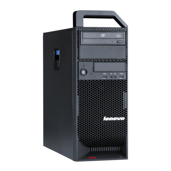
Page 100: Locating Controls And Connectors On The Front Of Your Computer
Locating controls and connectors on the front of your computer The following illustration shows the location of the controls and connectors on the front of your computer. Optical drive (some models) USB connector 3.5-inch diskette drive or card Hard disk drive activity light reader (some models) USB connector Power button... -
Page 101: Rear Connectors
Rear connectors The following illustration shows the locations of the connectors on the rear of the computer. Power cord connector Microphone connector Serial port Audio line-out rear speakers connector Ethernet connector SPDIF (Sony Philips Digital Interconnect Format) out connector Serial port (some models) USB connectors (8) Audio line-out subwoofer/center Optical SPDIF in connector... -
Page 102: Removing The Cover
Removing the cover CAUTION: The heat sink and microprocessor might be very hot. Turn off the computer and wait three to five minutes to let the computer cool before opening the computer cover. To remove the computer cover: 1. Remove any media from the drives and shut down your operating system. Turn off all attached devices. -
Page 103: Locations
Locations The following illustration will help you locate the major FRUs in the computer. Microprocessor, heat sink, and heat Hard disk drives sink fan assembly Optical drive Rear fan assembly 3.5-inch diskette drive or card reader Power supply Internal speaker Chapter 10. -
Page 104: Locating Parts On The System Board
Locating parts on the system board Microprocessor 12 V power Front panel connector connector Microprocessor fan connector Cover presence switch connector Microprocessor Thermal sensor connector Memory slots (6) PS/2 connector 24-pin system power connector Front audio connector Hard disk drive fan assembly Internal speaker connector connector Diskette drive connector... -
Page 105: Removing The Front Bezel
Removing the front bezel To remove the front bezel: 1. Remove the cover. See “Removing the cover” on page 96. 2. Remove the front bezel by releasing the three plastic tabs 1 on the left side and pivoting the bezel outward. 3. -
Page 106: Replacing The Power Supply
“Important safety information” in the ThinkStation Safety and Warranty Guide that came with your computer. To obtain a copy of the ThinkStation Safety and Warranty Guide, go to: http://www.lenovo.com/support This section provides information on how to remove or replace the power supply. - Page 107 Chapter 10. Replacing FRUs - Menorca Computers...
-
Page 108: Replacing A Memory Module
8. Install the new power supply into the chassis so that the screw holes in the power supply align with those in the chassis. Note: Use only the screws provided by Lenovo. 9. Install and tighten the five screws at the rear of the chassis to secure the power supply. - Page 109 CAUTION: The memory module might be very hot. Turn off the computer and wait three to five minutes to let the computer cool before opening the computer cover. This section provides instructions on how to replace a memory module. Your computer has 6 slots for installing or replacing DDR3 UDIMMs (double data rate 3 error correction code unbuffered dual inline memory modules).
-
Page 110: Replacing A Pci Adapter Card
“Important safety information” in the ThinkStation Safety and Warranty Guide that came with your computer. To obtain a copy of the ThinkStation Safety and Warranty Guide, go to: http://www.lenovo.com/support This section provides information on how to remove or replace a PCI adapter card. - Page 111 3. Take note of the location of all cable connections on the adapter card. It will be necessary to reconnect them properly when installing a new adapter card. 4. Disconnect all cables connected to the adapter card. See “Locating parts on the system board”...
- Page 112 Hardware Maintenance Manual...
- Page 113 7. Remove the new adapter card from its static-protective package. 8. Install the new adapter card into the appropriate adapter card slot on the system board. See “Locating parts on the system board” on page 98. Chapter 10. Replacing FRUs - Menorca Computers...
- Page 114 Hardware Maintenance Manual...
-
Page 115: Replacing The Heat Sink
“Important safety information” in the ThinkStation Safety and Warranty Guide that came with your computer. To obtain a copy of the ThinkStation Safety and Warranty Guide, go to: http://www.lenovo.com/support This section provides instructions on how to replace and install the heat sink. - Page 116 5. Carefully lift the heat sink off of the system board. 6. Remove the plastic cover from the bottom of the new heat sink to expose the heat sink grease (this cover protects the heat sink grease from contamination). Notes: a.
-
Page 117: Replacing The Microprocessor
“Important safety information” in the ThinkStation Safety and Warranty Guide that came with your computer. To obtain a copy of the ThinkStation Safety and Warranty Guide, go to: http://www.lenovo.com/support This section provides instructions on how to replace the microprocessor. To replace the microprocessor: 1. - Page 118 Hardware Maintenance Manual...
- Page 119 Notes: a. Note the orientation of the notches 1 on the microprocessor. This is important when reinstalling the microprocessor on the new system board. b. Do not drop anything onto the microprocessor socket while it is exposed. The socket pins must be kept as clean as possible. 6.
-
Page 120: Replacing The System Board
“Important safety information” in the ThinkStation Safety and Warranty Guide that came with your computer. To obtain a copy of the ThinkStation Safety and Warranty Guide, go to: http://www.lenovo.com/support Note: When replacing the system board a new retention module for the microprocessor heat sink is required. - Page 121 6. Remove the heat sink from the failing system board. See “Replacing the heat sink” on page 109. 7. Note the location of all cable connections on the system board and disconnect all cables. See “Locating parts on the system board” on page 98. 8.
- Page 122 Note: Your microprocessor socket and cover might look slightly different from the illustration. Hardware Maintenance Manual...
-
Page 123: Replacing A Hard Disk Drive
“Important safety information” in the ThinkStation Safety and Warranty Guide that came with your computer. To obtain a copy of the ThinkStation Safety and Warranty Guide, go to: http://www.lenovo.com/support This section provides instructions on how to replace a hard disk drive. - Page 124 Important When you receive a new hard disk drive, you also receive a set of Product Recovery discs. The set of Product Recovery discs will enable you to restore the contents of the hard disk drive to the same state as when your computer was originally shipped from the factory.
- Page 125 4. Pull the bracket handle out to remove the hard disk drive from the chassis. 5. Remove the failing hard disk drive from the bracket by flexing the bracket. Chapter 10. Replacing FRUs - Menorca Computers...
- Page 126 6. To install the new hard disk drive into the bracket, flex the bracket, and then align pin 1 , pin 2 , pin 3 , and pin 4 on the bracket with the holes in the hard disk drive. Do not touch the circuit board 5 on the bottom of the hard disk drive.
-
Page 127: Replacing The Hard Disk Drive Fan Assembly
Do not open your computer or attempt any repair before reading and understanding the “Important safety information” in the ThinkStation Safety and Warranty Guide that came with your computer. To obtain a copy of the ThinkStation Safety and Warranty Guide, go to: http://www.lenovo.com/support Chapter 10. Replacing FRUs - Menorca Computers... - Page 128 Your computer might have a hard disk drive fan assembly installed. To replace the hard disk drive fan assembly: 1. Remove the computer cover. See “Removing the cover” on page 96. 2. Locate the hard disk drive fan assembly. The hard disk drive fan assembly is attached to the side of the hard disk drive bay.
-
Page 129: Replacing An Optical Drive
“Important safety information” in the ThinkStation Safety and Warranty Guide that came with your computer. To obtain a copy of the ThinkStation Safety and Warranty Guide, go to: http://www.lenovo.com/support This section provides instructions on how to replace an optical drive. -
Page 130: Replacing The Diskette Drive Or Card Reader
“Important safety information” in the ThinkStation Safety and Warranty Guide that came with your computer. To obtain a copy of the ThinkStation Safety and Warranty Guide, go to: http://www.lenovo.com/support This section provides instructions on how to replace the diskette drive or card reader. - Page 131 2. Remove the front bezel. See “Removing the front bezel” on page 99. 3. Locate the diskette drive or card reader. See “Locations” on page 97. 4. Disconnect the signal and power cables from the rear of the diskette drive. If you are replacing a card reader, disconnect the card reader cable from the system board.
-
Page 132: Replacing The Front And Rear Fan Assemblies
“Important safety information” in the ThinkStation Safety and Warranty Guide that came with your computer. To obtain a copy of the ThinkStation Safety and Warranty Guide, go to: http://www.lenovo.com/support This section provides instructions on how to replace the front or rear fan assembly. -
Page 133: Replacing The Front Panel Connectors Assembly
“Important safety information” in the ThinkStation Safety and Warranty Guide that came with your computer. To obtain a copy of the ThinkStation Safety and Warranty Guide, go to: http://www.lenovo.com/support This section provides instructions on how to replace the front panel connectors assembly. -
Page 134: Replacing The Power Switch/Led Assembly
Do not open your computer or attempt any repair before reading and understanding the “Important safety information” in the ThinkStation Safety and Warranty Guide that came with your computer. To obtain a copy of the ThinkStation Safety and Warranty Guide, go to: http://www.lenovo.com/support Hardware Maintenance Manual... -
Page 135: Replacing The Battery
“Important safety information” in the ThinkStation Safety and Warranty Guide that came with your computer. To obtain a copy of the ThinkStation Safety and Warranty Guide, go to: http://www.lenovo.com/support Your computer has a special type of memory that maintains the date, time, and settings for built-in features, such as serial-port assignments (configuration). -
Page 136: Replacing The Internal Speaker
“Important safety information” in the ThinkStation Safety and Warranty Guide that came with your computer. To obtain a copy of the ThinkStation Safety and Warranty Guide, go to: http://www.lenovo.com/support This section provides instructions on how to replace the internal speaker. -
Page 137: Completing The Fru Replacement
6. Remove the speaker and speaker cable from the computer. 7. Route the new speaker cable and then position the new internal speaker tabs 3 into the metal speaker slots and then push the internal speaker downward until the speaker locking tabs snap into position. 8. - Page 138 5. Some FRU replacements require the configuration to be updated. See Chapter 6, “Using the Setup Utility,” on page 51. Hardware Maintenance Manual...
-
Page 139: Chapter 11. Replacing Frus (Type 4155, 4158, 4218)
The following illustration shows the location of the controls and connectors on the front of your computer. Note: Not all computer models will have the following controls and connections. USB connector USB connector Microphone connector IEEE 1394 connector Headphone connector © Copyright Lenovo 2008... -
Page 140: Rear Connectors
Rear connectors The following illustration shows the locations of the connectors on the rear of the computer. Power cord connector Audio line-out front speakers connector IEEE 1394 connector Microphone connector Serial port Audio line-out rear speakers connector Ethernet connectors (2) Audio line-out side speaker connector Audio line-out subwoofer/center USB connectors (8) -
Page 141: Removing The Cover
Removing the cover CAUTION: The heat sink and microprocessor might be very hot. Turn off the computer and wait three to five minutes to let the computer cool before opening the computer cover. To remove the computer cover: 1. Remove any media from the drives and shut down your operating system. Turn off all attached devices. -
Page 142: Locations
Locations The following illustration will help you locate the major FRUs in the computer. Microprocessors and heat sinks (2) Hard disk drive bays (5) Optical drive bays (3) Hard disk drive fan assembly Internal speaker Adapter card retainer 3.5-inch diskette drive or card reader Rear fan assembly Front bezel Power supply assembly... -
Page 143: Locating Parts On The System Board
Locating parts on the system board CPU 1 memory slots (6) Hard disk drive connectors (5) Microprocessor and heat sink 1 Optical drive connectors (3) CPU 1 fan connector Battery CPU 1 12 V power connector Clear CMOS/Recovery jumper CPU 1 memory fan connector Thermal sensor connector Microprocessor and heat sink 2 Cover presence switch connector... -
Page 144: Replacing The Power Supply
2. Remove the front bezel by releasing the three plastic tabs 1 on the left side and pivoting the bezel outward. 3. Lay the front bezel on a flat surface. 4. To reinstall the bezel, align the plastic tabs on the right side of the bezel with the corresponding holes in the chassis, then pivot the bezel inward until it snaps into position on the left side. - Page 145 “Important safety information” in the ThinkStation Safety and Warranty Guide that came with your computer. To obtain a copy of the ThinkStation Safety and Warranty Guide, go to: http://www.lenovo.com/support This section provides information about how to move and replace the power supply.
- Page 146 5. Remove the six power supply retaining screws at the rear of the chassis and inside the chassis. Hardware Maintenance Manual...
-
Page 147: Installing Or Replacing A Memory Module
8. Install the new power supply into the chassis so that the screw holes in the power supply align with those in the chassis. Note: Use only the screws provided by Lenovo. 9. Install and tighten the four screws at the rear of the chassis to secure the power supply. - Page 148 example: If you are to install six 1 GB DIMMs in a dual-processor system, three of the 1 GB DIMMs should be installed in the CPU1 slots, and the other three should be installed in the CPU2 slots. v Memory must always be installed in the blue sockets first, starting with the blue socket closest to each respective CPU.
- Page 149 6. Position the new memory module over the memory slot. Make sure the notch 1 on the memory module aligns correctly with the slot key 2 on the system board. Push the memory module straight down into the slot until the retaining clips close.
-
Page 150: Replacing A Pci Adapter Card
“Important safety information” in the ThinkStation Safety and Warranty Guide that came with your computer. To obtain a copy of the ThinkStation Safety and Warranty Guide, go to: http://www.lenovo.com/support This section provides information about how to replace a PCI adapter card. - Page 151 3. Take note of the location of all cable connections on the adapter card. It will be necessary to reconnect them properly when installing a new card. 4. Disconnect all cables connected to the adapter card. See “Locating parts on the system board”...
- Page 152 Hardware Maintenance Manual...
-
Page 153: Replacing The Heat Sink
“Important safety information” in the ThinkStation Safety and Warranty Guide that came with your computer. To obtain a copy of the ThinkStation Safety and Warranty Guide, go to: http://www.lenovo.com/support This section provides instructions on how to replace and install the heat sink. - Page 154 5. Carefully lift the heat sink off of the system board. 6. Remove the plastic cover from the bottom of the new heat sink to expose the heat sink grease (this cover protects the heat sink grease from contamination). Notes: a.
-
Page 155: Replacing The Microprocessor
“Important safety information” in the ThinkStation Safety and Warranty Guide that came with your computer. To obtain a copy of the ThinkStation Safety and Warranty Guide, go to: http://www.lenovo.com/support This section provides instructions on how to replace the microprocessor. To replace the microprocessor: 1. - Page 156 Notes: a. Note the orientation of the notches 1 on the microprocessor. This is important when reinstalling the microprocessor on the new system board. b. Do not drop anything onto the microprocessor socket while it is exposed. The socket pins must be kept as clean as possible. 6.
-
Page 157: Replacing The System Board
“Important safety information” in the ThinkStation Safety and Warranty Guide that came with your computer. To obtain a copy of the ThinkStation Safety and Warranty Guide, go to: http://www.lenovo.com/support Note: When replacing the system board a new retention module for the microprocessor heat sink is required. - Page 158 7. Note the location of all cable connections on the system board and disconnect all cables. See “Locating parts on the system board” on page 137. 8. Remove the nine screws that secure the system board to the chassis, following the sequence shown in the figure: 9.
- Page 159 Note: Your microprocessor socket and cover might look slightly different from the illustration. Chapter 11. Replacing FRUs - Ibiza Computers...
-
Page 160: Replacing A Hard Disk Drive
“Important safety information” in the ThinkStation Safety and Warranty Guide that came with your computer. To obtain a copy of the ThinkStation Safety and Warranty Guide, go to: http://www.lenovo.com/support This section provides instructions on how to replace the hard disk drive. - Page 161 Important When you receive a new hard disk drive, you also receive a set of Product Recovery discs. The set of Product Recovery discs will enable you to restore the contents of the hard disk drive to the factory-installed state. For more information on recovering factory-installed software, refer to “Recovering software”...
- Page 162 Figure 6. Installing a 3.5-inch hard disk drive into the bracket Note: If you are installing a 2.5-inch hard disk drive into the bracket, flex the bracket, and then align pin 1 , pin 2 , pin 3 , and pin 4 on the bracket with the holes in the hard disk drive adapter 5 .
-
Page 163: Replacing The Hard Disk Drive Fan Assembly
Do not open your computer or attempt any repair before reading and understanding the “Important safety information” in the ThinkStation Safety and Warranty Guide that came with your computer. To obtain a copy of the ThinkStation Safety and Warranty Guide, go to: http://www.lenovo.com/support Chapter 11. Replacing FRUs - Ibiza Computers... - Page 164 This section provides instructions on how to replace the hard disk drive fan assembly. To replace the hard disk drive fan assembly: 1. Remove the computer cover. See “Removing the cover” on page 96. 2. Locate the hard disk drive fan assembly. See “Locations” on page 97. 3.
-
Page 165: Replacing An Optical Drive
“Important safety information” in the ThinkStation Safety and Warranty Guide that came with your computer. To obtain a copy of the ThinkStation Safety and Warranty Guide, go to: http://www.lenovo.com/support This section provides instructions on how to replace an optical drive. -
Page 166: Replacing The Diskette Drive Or Card Reader
“Important safety information” in the ThinkStation Safety and Warranty Guide that came with your computer. To obtain a copy of the ThinkStation Safety and Warranty Guide, go to: http://www.lenovo.com/support This section provides instructions on how to replace the diskette drive or card reader. - Page 167 4. Access system board components. 5. Note the routing of the signal cable. Disconnect the signal cable from the system board. 6. Press the drive latch 1 and slide the diskette drive or card reader out the front of the chassis. Chapter 11.
-
Page 168: Replacing The Front And Rear Fan Assemblies
“Important safety information” in the ThinkStation Safety and Warranty Guide that came with your computer. To obtain a copy of the ThinkStation Safety and Warranty Guide, go to: http://www.lenovo.com/support This section provides instructions on how to replace the front and rear fan assemblies. -
Page 169: Replacing The Front Panel Connectors Assembly
“Important safety information” in the ThinkStation Safety and Warranty Guide that came with your computer. To obtain a copy of the ThinkStation Safety and Warranty Guide, go to: http://www.lenovo.com/support This section provides instructions on how to replace the front panel connectors assembly. -
Page 170: Replacing The Power Switch/Led Assembly
“Important safety information” in the ThinkStation Safety and Warranty Guide that came with your computer. To obtain a copy of the ThinkStation Safety and Warranty Guide, go to: http://www.lenovo.com/support This procedure describes how to remove and replace the power switch/LED assembly. -
Page 171: Replacing The Battery
“Important safety information” in the ThinkStation Safety and Warranty Guide that came with your computer. To obtain a copy of the ThinkStation Safety and Warranty Guide, go to: http://www.lenovo.com/support Your computer has a special type of memory that maintains the date, time, and settings for built-in features, such as serial-port assignments (configuration). -
Page 172: Replacing The Internal Speaker
“Important safety information” in the ThinkStation Safety and Warranty Guide that came with your computer. To obtain a copy of the ThinkStation Safety and Warranty Guide, go to: http://www.lenovo.com/support This section provides instructions on how to replace the internal speaker. -
Page 173: Completing The Fru Replacement
6. Route the new internal speaker cable and power LED cable, and then position the two internal speaker latches 2 into the metal slots in the chassis, then push the internal speaker upwards until it snaps into position. 7. Connect the internal speaker cable and the power LED cable to the system board. - Page 174 Hardware Maintenance Manual...
-
Page 175: Chapter 12. Fru Lists
C5H B2M B3M A1J A2J 94G 99U 99F 99S C9A C7A C7Q C7K CTO) Microprocessor, Intel Xeon W3540 - 2.93GHz, Quad Core - 5.86 QPI, 8MB L2, 46R6406 DDR3-1066, Turbo, SMT, 130W (models 39U 39F 57U 57F C8A C8Q C8K CTO) © Copyright Lenovo 2008... - Page 176 Item # 4105 FRUs FRU# CRU Tier Microprocessor, Intel Xeon W3570 - 3.20GHz, Quad Core- 6.4 QPI, 8MB L2, 46R6407 DDR3-1333, Turbo, SMT, 130W (models 58U 58F CTO) Microprocessor, Intel Xeon W3550 - Quad Core - 3.06GHz - 4.8 QPI, 8MB Cache, 64Y9827 DDR3-1066, Turbo, SMT, 130W (models 64G 68J 69J 72J 76M 78M 79U 79F 82C 83C 84H 88V 89Q 89C 93Q A9M B1M A3J A4J A5J D4J CTO)
- Page 177 Item # 4105 FRUs FRU# CRU Tier Microprocessor, Intel Xeon X5670 - 6 Core - 2.93GHz - 6.4 QPI DDR3-1333-12MB 71Y9037 Turbo SMT 95W (models CTO) Microprocessor, Intel Xeon W5580 - 3.20GHz, Quad Core 6.4 QPI, 8MB L2, 46R6641 DDR3-1333, Turbo, SMT, 130W (models 16U 16F CTO) Microprocessor, Intel Xeon W3503 - Dual Core - 2.4Ghz - 4.8 QPI, 4MB L2, 63Y9159 DDR3-1066, 130W (models 54U 54F 59G 74M 77M B5M B6M 96G 97U 97F 97S...
- Page 178 Item # 4105 FRUs FRU# CRU Tier System Board, 1P Intel LGA 1366, Tylersburg 36S, ICH10R (v1.45, TPM enabled) 71Y8820 (models 18C 19C 19B 19H 19V 21C 21B 21H 21V 11U 11F 12U 12F 13U 13F 14U 14F 15U 15F 16U 16F 17U 17F 27G 24G 25G 26G 32B 32H 32V 32C 33B 33H 33V 33C 34B 34H 34V 34C18H 18V 18K 42Q 43Q 44A 44T 44K 45A 45T 45K 35M 36M 37M 38U 38F 39U 39F 41U 23G 28G 29G 31G 46M 46A 46Q 46T 47J 48M 48A 48Q 48T 49J 51C 51B 51H 51V 52C 52B 52H 52V 53C 53B 53H 53V 54U 54F 55U 55F...
- Page 179 Item # 4105 FRUs FRU# CRU Tier Optical drive, DVD Burner/CD-RW Rambo 8 (SATA) - DOS/Linux (models 11U 71Y5545 11F 12U 12F 13U 13F 14U 14F 15U 15F 16U 16F 17U 17F 27G 24G 25G 26G 32B 32H 32V 32C 33B 33H 33V 33C 34B 34H 34V 34C 18H 18V 18B 42Q 43Q 44A 44T 44K 45A 45T 45K 35M 36M 37M 38U 38F 39U 39F 41U 23G 28G 29G 31G 46M 46A 46Q 46T 47J 48M 48A 48Q 48T 49J 51C 51B 51H 51V 52C 52B 52H 52V 53C 53B 53H 53V 54U 54F 55U 55F 56U 56F 57U 57F 58U 58F 59G 61G 62G 63G 64G...
- Page 180 Item # 4105 FRUs FRU# CRU Tier Hard disk drive, 128GB SATA Solid State Drive (SSD) - MLC, 1.8″ (models C9A 45N7953 E1M CTO) Hard disk drive, 128GB SATA Solid State Drive (SSD) - MLC, 1.8″ (models C9A 45N8203 E1M CTO) Hard disk drive, 256GB SATA Solid State Drive (SSD) - MLC, 1.8″...
- Page 181 SAS HDD filler (all models) 41R5552 Handle filler with screws (all models) 41R5699 4105 Keyboards (Lenovo Preferred Pro USB) FRU# CRU Tier USB --US English (models 19H 21H 11U 12U 13U 14U 15U 16U 17U 27G 24G 25G 26G 41A5289...
- Page 182 USB --Slovenian (models 27G 24G 25G 26G 23G 28G 29G 31G 59G 61G 62G 63G 64G 65G 41A5329 66G 67G 94G 95G 96G D1G D2G D3G CTO) 4105 Fingerprint Keyboards (Lenovo Preferred Pro USB) FRU# CRU Tier US English (models CTO)
- Page 183 4105 Fingerprint Keyboards (Lenovo Preferred Pro USB) FRU# CRU Tier Brazilian Portuguese (models CTO) 41R0043 Bulgarian (models CTO) 41R0044 Chinese/US (models CTO) 41R0045 Czech (ABB) (models CTO) 41R0046 Danish (models CTO) 41R0047 Dutch (models CTO) 41R0048 French (models CTO) 41R0049...
- Page 184 B9M C1M C2J A1J A2J A3J A4J A5J A6J A7J D4J D5J D6J D7J D8M D9M E1M) Speakers (2-piece) Lenovo Logo (Primary) (models CTO) 41A5331 Speakers (2-piece) Lenovo Logo (Secondary) (models CTO) 41A5334 Lenovo 3 pieces Speakers (China Only) (models CTO) 45C8640 Lenovo 2 pieces Speakers (China Only) (models CTO) 45C8641 Speaker Power brick (models CTO)
- Page 185 4105 Adapters and miscellaneous FRUs FRU# 1GB NVIDIA FX3800 (DVI + DP + ST), 2x3 Pwr Conn. (models 76M 82C 88V C4C A9M 89Y0429 D9M E1M CTO) 4GB NVIDIA FX5800 (DVI + DVI + DP + ST), 2*2X3 Pwr Conn. (models CTO) 46R2794 256MB ATI FirePro V3700 (Dual DVI) (models 44A 44T 44K 39U 39F 59G 77M 89Q 89C 53Y8569...
- Page 186 4105 Power Cords FRU# Power cord - UK, Ireland, Singapore, Malaysia, Brunei, Hong Kong (models 19B 19H 21B 41R3224 21H 32B 32H 33B 33H 34B 34H 18H 18B 51B 51H 52B 52H 53B 53H C5B C5H CTO) Power cord - UK, Ireland, Singapore, Malaysia, Brunei, Hong Kong (models 19B 19H 21B 41R3225 21H 32B 32H 33B 33H 34B 34H 18H 18B 51B 51H 52B 52H 53B 53H C5B C5H CTO) Power cord - Taiwan (models 19V 18V 51V 52V 53V 86V 87V 88V CTO)
- Page 187 4105 Windows XP Pro Recovery DVDs FRU# Danish (models 59G 61G 65G CTO) 64Y3599 Dutch (models 59G 61G 65G CTO) 64Y3600 Arabic English (models 59G 61G 65G CTO) 64Y3605 SV (Swedish) (models 59G 61G 65G CTO) 64Y3598 Hebrew (models 59G 61G 65G CTO) 64Y3603 Finland (models 59G 61G 65G CTO) 64Y3602...
- Page 188 4105 Vista Business 32 Recovery DVDs FRU# Hungarian (models 23G 28G CTO) 64Y3682 Greek (models 23G 28G CTO) 64Y3683 Simplified Chinese (models 18C 19C 21C CTO) 64Y5663 Traditional Chinese TC (models 19V 21V CTO) 64Y3686 Traditional Chinese HK (models 19B 21B CTO) 64Y3687 Korean (models 44K 45K CTO) 64Y3688...
- Page 189 4105 Vista Business 64 Recovery DVDs FRU# Trad Chinese (models 32B 33B 34B 18B 51B 52B 53B CTO) 64Y3786 Korean (models CTO) 64Y3787 Slovenian (models 27G 24G 25G 26G 29G 31G 62G 63G 64G CTO) 64Y3788 Portuguese (models 27G 24G 25G 26G 29G 31G 62G 63G 64G CTO) 64Y3792 Slovakian (models 27G 24G 25G 26G 29G 31G 62G 63G 64G CTO) 64Y3793...
- Page 190 4105 Windows 7 Professional 64 Recovery DVDs FRU# C&L Switzerland (EN FR GR IT) (models 94G 95G 96G D1G D2G D3G CTO) 71Y8583 Hardware Maintenance Manual...
-
Page 191: Machine Type 4155
Machine Type 4155 The FRUs listed in the following tables are not illustrated. Item # 4155 FRUs FRU# CRU Tier Power supply, 1060 Watt Power Supply (models 11C 11B 11H 11V 12C 12B 12H 41A9761 12V 14C 14B 14H 14V 15G 16G 19G 17G 18G 35C 35B 35H 35V 25J 26Q 27U 28U 28F 29U 29F 31U 31F 32U 32F 33U 33F 34U 34F 21G 22G 23G 24G 36C 36B 36H 36V 37C 37B 37H 37V 38C 38B 38H 38V 42G 43G 44J 45M 46M 47U 47F 48C 49C 51H 52V 53V 54Q 54C 55Q 55C 67B 67H 66C 63M 64M 65M 56J 57J 58J 59J 61J 62J... - Page 192 Item # 4155 FRUs FRU# CRU Tier Memory module, 8GB DDR3 4RX4 RDIMM PC3-8500 (1066MHz) (models CTO) 46R6025 Memory module, 1GB DDR3 ECC UDIMM PC3-8500 (1066MHz) (models 33U 33F 53Y6195 34U 34F 36B 36H 36V 74G CTO) Memory module, 2GB DDR3 ECC UDIMM PC3-8500 (1066MHz) (models 42G 43G 53Y6197 45M 46M 47U 47F 52V 67B 67H 73G CTO) Optical drive, DVD-ROM Drive - 16x/48x (SATA) - DOS/Linux (models 44J CTO)
-
Page 193: Item # 4155 Frus Fru# Cru Tier
Item # 4155 FRUs FRU# CRU Tier Hard disk drive, 450GB SAS - 15000 rpm, 3 Gb/s, 32MB cache, 3.5″ (models CTO) 45J4899 Hard disk drive, 128GB SATA Solid State Drive (SSD) - MLC, 1.8″ (models CTO) 45N7953 Hard disk drive, 128GB SATA Solid State Drive (SSD) - MLC, 1.8″ (models CTO) 45N8203 Hard disk drive, 256GB SATA Solid State Drive (SSD) - MLC, 1.8″... - Page 194 Item # 4155 FRUs FRU# CRU Tier Microprocessor, Intel Xeon X5660 - 6 Core - 2.80GHz - 6.4 QPI DDR3-1333-12MB 71Y9041 Turbo SMT 95W (models 78J CTO) Microprocessor, Intel Xeon X5667 - Quad Core - 3.06GHz - 6.4 QPI 71Y9039 DDR3-1333-12MB Turbo SMT 95W (models CTO) Microprocessor, Intel Xeon X5570, 2.93GHz, Quad Core, 6.4 QPI, 8MB L2, DDR3, 46R6640...
- Page 195 PS/2 card and bracket assembly (all models) 41R5694 PS/2 cable assembly (all models) 41R5604 4155 Keyboards (Lenovo Preferred Pro USB) FRU# CRU Tier USB --US English (models 11H 12H 15G 16G 19G 17G 35H 26Q 27U 28U 31U 32U 33U...
- Page 196 USB --US Euro (models 15G 16G 19G 17G 21G 22G 23G 24G 42G 43G 73G 74G 75G CTO) 41A5328 USB --Slovenian (models 15G 16G 19G 17G 21G 22G 23G 24G 42G 43G 73G 74G 75G 41A5329 CTO) 4155 Fingerprint Keyboards (Lenovo Preferred Pro USB) FRU# CRU Tier US English (models 18G 29U CTO) 41R0038...
- Page 197 4155 Fingerprint Keyboards (Lenovo Preferred Pro USB) FRU# CRU Tier Belgium English (models 18G CTO) 41R0042 Brazilian Portuguese (models CTO) 41R0043 Bulgarian (models 18G CTO) 41R0044 Chinese/US (models CTO) 41R0045 Czech (ABB) (models 18G CTO) 41R0046 Danish (models 18G CTO)
- Page 198 41D2781 Speakers (2-piece) Lenovo Logo (Primary) (models CTO) 41A5331 Speakers (2-piece) Lenovo Logo (Secondary) (models CTO) 41A5334 Lenovo 3 pieces Speakers (China Only) (models CTO) 45C8640 Lenovo 2 pieces Speakers (China Only) (models CTO) 45C8641 Speaker Power brick (models CTO)
- Page 199 4155 Adapters and miscellaneous FRUs FRU# SoundBlaster Titanium audio card (PCIe) (models CTO) 46T0407 Modem Phone Cable (models CTO) 39K5120 DVI to VGA Dongle (models CTO) 45C7816 512MB NVIDIA Quadro NVS 450 GDDR3 (DP+DP+DP+DP) (models CTO) 64Y9895 4155 Power Cords FRU# Power cord - US (models 27U 28U 28F 29U 29F 31U 31F 32U 32F 33U 33F 34U 34F 21G 41R3184...
- Page 200 4155 Power Cords FRU# Power cord - Switzerland (models 15G 16G 19G 17G 18G 21G 22G 23G 24G 42G 43G 73G 41R3229 74G 75G CTO) Power cord - Israel (models 15G 16G 19G 17G 18G 21G 22G 23G 24G 42G 43G 73G 74G 41R3236 75G CTO) Power cord - Israel (models 15G 16G 19G 17G 18G 21G 22G 23G 24G 42G 43G 73G 74G...
- Page 201 4155 Windows XP Pro Recovery DVDs FRU# Slovakian (models CTO) 64Y3612 Japanese (models CTO) 64Y5659 Simplified Chinese (models CTO) 64Y5660 Traditional Chinese Taiwan (models CTO) 64Y3614 Traditional Chinese Hong Kong (models CTO) 64Y3615 Korean (models CTO) 64Y3616 4155 Vista Business 32 Recovery DVDs FRU# English (models 11H 12H 14H CTO) 64Y5661...
- Page 202 4155 Vista Business 32 Recovery DVDs FRU# English for India (models CTO) 71Y3620 4155 Vista Business 64 Recovery DVDs FRU# English (models 15G 16G 19G 17G 18G 35H 26Q 27U 28U 29U31U 32U 33U 34U 21G 22G 64Y5664 23G 24G 36H 37H 38H 39U 41U 42G 43G 45M 46M 47U 51H 54Q 55Q CTO) Russian English (models 15G 16G 19G 17G 18G 21G 22G 23G 24G 42G 43G CTO) 64Y3771 French (models 15G 16G 19G 17G 18G 21G 22G 23G 24G 42G 43G 47F CTO)
- Page 203 4155 Windows 7 Professional 64 Recovery DVDs FRU# US English (models 67H 63M 64M 65M 68U 69A 69Q 71A 71Q 72A 72Q 73G 74G 75G 71Y8580 CTO) French (models 68F 73G 74G 75G CTO) 71Y8566 German (models 73G 74G 75G CTO) 71Y8568 Czech (models 73G 74G 75G CTO) 71Y8565...
-
Page 204: Machine Type 4157
Machine Type 4157 Item # 4157 FRUs FRU# CRU Tier Fan sink, Bloomfield Performance (all models) 41R5578 Fan sink, Bloomfield Workstation (all models) 41R5580 Microprocessor, Intel Xeon W3520 - 2.66Ghz, Quad Core - 4.8 QPI, 4MB L2, 46R6405 DDR3-1066, Turbo, SMT, 130W (models 25M 41G 57G 58G 69G 77M 79U 79F 81U 81F 91J 93M 94M 98G A2U A2F A7G B1U B1F B1S B1L B1D B1Y B1G B1M B1A B1Q B1T B1C B1B B1H B1V B1K B1R B1E B1J CTO) Microprocessor, Intel Xeon W3540 - 2.93GHz, Quad Core - 5.86 QPI, 8MB L2,... - Page 205 Item # 4157 FRUs FRU# CRU Tier Microprocessor, Intel Xeon E5504 - 2.00GHz, Quad Core- 4.8QPI, 4MB L2, 46R6631 DDR3-800, 80W (models 36G 33G 37G 41G 67G CTO) Microprocessor, Intel Xeon E5506 - 2.13GHz, Quad Core - 4.8QPI, 4MB L2, 46R6632 DDR3-800, 80W (models 14U 14F 15U 15F 15S 15P 15Y 32G 38G 49U 49F 52U 52F 47G 42G 59G CTO)
- Page 206 Item # 4157 FRUs FRU# CRU Tier Microprocessor, Intel Xeon W3670 - 6 Cores - 3.20GHz - 6.4 QPI DDR3-1333-12MB 71Y9027 Turbo SMT 130W (models CTO) Microprocessor, Intel Xeon W3565 - Quad Core - 3.2GHz - 4.8 QPI, 8MB Cache, 71Y8842 DDR3-1066, 130W (models A4G A8M CTO) System Board, 1P Intel LGA 1366 (models 23M 24M 25M 26M 27M 28A 28Q 28T...
-
Page 207: Memory Module, 8Gb Ddr3 4Rx4 Rdimm Pc3-8500 (1066Mhz) (Models Cto) 46R6025
Item # 4157 FRUs FRU# CRU Tier Memory module, 2GB DDR3 2RX8 RDIMM PC3-8500 (1066MHz) (models 44G 46R6023 45G CTO) Memory module, 4GB DDR3 2RX4 RDIMM PC3-8500 (1066MHz) (models CTO) 46R6024 Memory module, 8GB DDR3 4RX4 RDIMM PC3-8500 (1066MHz) (models CTO) 46R6025 Memory module, 1GB DDR3 ECC UDIMM PC3-8500 (1066MHz) (models 54G 58G 53Y6195... - Page 208 Item # 4157 FRUs FRU# CRU Tier Hard disk drive, 750GB SATA - 7200 rpm (models 42G 44G 41G CTO) 43C3671 Hard disk drive, 1TB SATA - 7200 rpm (models 59G 61G CTO) 46R6031 Hard disk drive, 74GB SATA - 10000 rpm (models CTO) 46R6032 Hard disk drive, 150GB SATA - 10000 rpm (models 28A 28Q 28T 28K13U 13F 33G 46R6400...
- Page 209 SAS HDD filler (all models) 41R5552 Handle filler with screws (all models) 41R5699 4157 Keyboards (Lenovo Preferred Pro USB) FRU# CRU Tier Full size --US English (models 23M 24M 25M 26M 27M 28A 28Q 29A 29Q 31A 11U 12U 41A5289...
- Page 210 4157 Keyboards (Lenovo Preferred Pro USB) FRU# CRU Tier Full size --Dutch (models 34G 35G 36G 32G 33G 37G 38G 39G 41G 47G 44G 45G 46G 54G 41A5299 55G 56G 57G 58G 59G 61G 62G 63G 64G 65G 66G 67G 68G 69G A3G A4G A5G A6G A7G...
- Page 211 41A5329 54G 55G 56G 57G 58G 59G 61G 62G 63G 64G 65G 66G 67G 68G 69G A3G A4G A5G A6G A7G B1G CTO) 4157 Fingerprint Keyboards (Lenovo Preferred Pro USB) FRU# CRU Tier Full size -- US English (models CTO)
- Page 212 4157 Fingerprint Keyboards (Lenovo Preferred Pro USB) FRU# CRU Tier Full size -- French (models CTO) 41R0049 Full size -- French Canadian (models CTO) 41R0050 Full size -- French Canadian (models CTO) 41R0051 Full size -- German (models CTO) 41R0052...
- Page 213 21J 22J 29A 29Q 29T 29K 31A 31K 13U 13F 14U 14F 15U 15F 15S 15P 15Y 43S 43P 43Y CTO 88J 89J 91J 92J 93M 94M 95M 96M CTO) Speakers (2-piece) Lenovo Logo(Primary) (models CTO) 41A5331 Speakers (2-piece) Lenovo Logo(Secondary) (models CTO) 41A5334 Chapter 12.
- Page 214 4157 Adapters and miscellaneous FRUs FRU# Lenovo 3 pieces Speakers (China Only) (models CTO) 45C8640 Lenovo 2 pieces Speakers (China Only) (models CTO) 45C8641 Speaker Power brick (models CTO) 89P8571 256MB NVIDIA NVS290 (DMS59 Connector) - Quasar (models 15U 15F 36G CTO)
- Page 215 4157 Power Cords FRU# Power cord - Brazil (Portuguese) (models CTO) 41R3270 Power cord - Brazil (Portuguese) (models CTO) 41R3271 Power cord - LA High Volt (APU) (models B1L B1Y CTO) 41R3176 Power cord - LA High Volt (APU) (models B1L B1Y CTO) 41R3177 Power cord - ANZ (models 27A 28A 28T 29A 29T 31A 11U 11F 12U 12F 13U 13F 14U 14F 41R3196...
- Page 216 4157 Power Cords FRU# Power cord - South Africa (models 223M 24M 25M 26M 27M 27A 28A 29A 31A 34G 35G 41R3220 36G 32G 33G 37G 38G 39G 41G 42G 47G 44G 45G 46G 54G 55G 56G 57G 58G 59G 61G 62G 63G 64G 65G 66G 67G 68G 69G 77M 78M 83A 84A 85A 93M 94M 95M 96M 97M 98G 99G A3G A4G A5G A6G A7G A8M A9M B1G B1M B1A CTO) Power cord - South Africa (models 223M 24M 25M 26M 27M 27A 28A 29A 31A 34G 35G...
- Page 217 4157 Vista Business 32 Recovery DVDs FRU# English (models 11U 12U 14U 15U 16U 18U 48U 47G 46G CTO) 64Y5661 Russian English (models 47G 46G CTO) 64Y3672 French (models 11F 12F 14F15F 16F 18F 48F CTO) 64Y3673 German (models 47G 46G CTO) 64Y3674 Spanish (models 15S 15Y CTO) 64Y3675...
- Page 218 4157 Vista Business 64 Recovery DVDs FRU# French (models 13F 17F 34G 35G 36G 32G 33G 37G 38G 39G 41G 42G 49F 51F 52F 54G 64Y3772 57G 58G 59G 61G 62G 63G 64G 65G 66G 68G 69G 79F 81F 82F CTO) German (models 34G 35G 36G 32G 33G 37G 38G 39G 41G 42G 44G 45G 54G 57G 58G 59G 64Y3773 68G 69G CTO)
- Page 219 4157 Vista Business 64 Recovery DVDs FRU# MUL DVD P/Ns VB64 C&L1 Nordics (EN DK FI NO SV) (models 34G 35G 36G 32G 33G 64Y3798 37G 38G 39G 41G 42G 44G 45G 54G 57G 58G 59G 68G 69G CTO) MUL DVD P/Ns VB64 C&L 2 Switzerland (EN FR GR IT) (models 34G 35G 36G 32G 33G 64Y3799 37G 38G 39G 41G 42G 44G 45G 54G 57G 58G 59G 68G 69G CTO) MUL DVD P/Ns VB64 C&L3 Bel Lux (EN FR GR NL) (models 34G 35G 36G 32G 33G 37G...
-
Page 220: Machine Type 4158
Machine Type 4158 The FRUs listed in the following tables are not illustrated. Item # 4158 FRUs FRU# CRU Tier Power supply, 1060 Watt Power Supply—2P (models 18A 18T 18K 19A 19K 13J 41A9761 14M 15M 16M 17M 21U 21F 22U 22F 23U 23F 24U 24F 25U 25F 26U 26F 27U 27F 28U 28F 29U 29F 31U 31F 32G 33G 34G 35G 36G 37G 44S 44P 44Y 45S 52U 53U 49U 49F 51U 51F 46G 47G 48G 54C 54B 54H 54V 55G 56G 57G 58G 59G 61G 62G 63M 64J 65Q 66Q 67Q 68Q 69Q 71M 72M 73M 74M 75J 76Q 76J 77J 78J 79U 79F... - Page 221 Item # 4158 FRUs FRU# CRU Tier Memory module, 8GB DDR3 4RX4 RDIMM PC3-8500 (1066MHz) (models 64J 46R6025 CTO) Memory module, 1GB DDR3 ECC UDIMM PC3-8500 (1066MHz) (models 51U 51F 53Y6195 62G CTO) Memory module, 2GB DDR3 ECC UDIMM PC3-8500 (1066MHz) (models 46G 47G 53Y6197 48G 55G 56G 57G 58G 59G 61G 63M 65Q 66Q 68Q 69Q 71M 82G 83G 87U 87F 87S 87L 87D 87Y 87G 87M 87A 87Q 87T 87C 87B 87H 87V 87K 87R 87E 87J CTO)
- Page 222 Item # 4158 FRUs FRU# CRU Tier Hard disk drive, 300GB SAS - 15000 rpm (models 12J 15M 17M CTO) 43C6969 Hard disk drive, 300GB SAS - 15000 rpm (models 12J 15M 17M 74M 76Q 76J CTO) 45K0609 Hard disk drive, 450GB SAS - 15000 rpm, 3 Gb/s, 32MB cache, 3.5″ (models CTO) 45J4899 Hard disk drive, 128GB SATA Solid State Drive (SSD) - MLC, 1.8″...
- Page 223 Item # 4158 FRUs FRU# CRU Tier Microprocessor, Intel Xeon X5560 - 2.80GHz, Quad Core - 6.4 QPI, 8MB L2, 46R6639 DDR3-1333, Turbo, SMT, 95W (models 19A 19K 13J 22U 22F 23U 23F 28U 28F 33G 43G 38G 39G 48G 59G CTO) Microprocessor, Intel Xeon X5650 - 6 Core - 2.66GHz - 6.4 QPI DDR3-1333-12MB 71Y9043 Turbo SMT 95W (models CTO)
- Page 224 PS/2 card and bracket assembly (all models) 41R5694 PS/2 cable assembly (all models) 41R5604 4158 Keyboards (Lenovo Preferred Pro USB) FRU# CRU Tier USB --US English (models 18A 19A 14M 15M 16M 17M 22U 23U 24U 25U 26U 27U 28U...
- Page 225 4158 Keyboards (Lenovo Preferred Pro USB) FRU# CRU Tier USB -- Hong Kong/Taiwan (models 54B 54V 87B 87V CTO) 41A5296 USB --Czech (ABB) (models 32G 33G 46G 47G 48G 55G 56G 57G 58G 59G 61G 62G 81G 41A5297 82G 83G 87G CTO)
- Page 226 USB --Slovenian (models 32G 33G 46G 47G 48G 55G 56G 57G 58G 59G 61G 62G 81G 82G 41A5329 83G 87G CTO) 4158 Fingerprint Keyboards (Lenovo Preferred Pro USB) FRU# CRU Tier US English (models 21U 41G 42G 43G 34G 35G 36G 37G 38G 39G CTO)
- Page 227 76J 77J 78J 79U 79F CTO) Speakers (2-piece) Lenovo Logo (Primary) (models CTO) 41A5331 Speakers (2-piece) Lenovo Logo (Secondary) (models CTO) 41A5334 Lenovo 3 pieces Speakers (China Only) (models CTO) 45C8640 Lenovo 2 pieces Speakers (China Only) (models CTO) 45C8641 Speaker Power brick (models CTO)
- Page 228 4158 Adapters and miscellaneous FRUs FRU# 256MB NVIDIA FX380 (DVI + DP) (Hard from 46R2784) (models 26U 26F CTO) 71Y6863 512MB NVIDIA FX580 (DVI + DP + DP) (models 28U 28F 31U 31F CTO) 46R2786 768MB NVIDIA FX1800 (DVI + DP + DP) (models 18A 18T 18K 19A 19K 13J 14M 16M 17M 46R2788 21U 21F 22U 22F 24U 24F 25U 25F 27U 27F 29U 29F 32G 42G 43G 34G 37G 39G 44S 44P 44Y 45S 46G 54C 54B 54H 54V 55G 65Q 68Q 69Q 72M 73M 79U 79F 81G 82G 87U 87F 87S...
- Page 229 4158 Power Cords FRU# Power cord - Korea (models 18K 19K 87K 87R CTO) 41R3260 Power cord - Korea (models 18K 19K 87K 87R CTO) 41R3261 Power cord - UK, Ireland, Singapore, Malaysia, Brunei, Hong kong (models 55G 56G 57G 41R3224 58G 59G 61G 62G 63M 81G 82G 83G 87G CTO) Power cord - UK, Ireland, Singapore, Malaysia, Brunei, Hong kong (models 55G 56G 57G...
- Page 230 4158 Windows XP Pro Recovery DVDs FRU# US English/UK/Asia Pacific (models CTO) 89Y0109 French/French Canadian (models CTO) 64Y3591 German (models CTO) 64Y3592 Italy (models CTO) 64Y3595 Brazil (models CTO) 64Y3594 Spanish/LA Spanish (models CTO) 64Y3593 Danish (models CTO 64Y3599 Dutch (models CTO) 64Y3600 Arabic English (models CTO) 64Y3605...
- Page 231 4158 Vista Business 32 Recovery DVDs FRU# Czech (models CTO) 64Y3678 Finnish (models CTO) 64Y3698 Polish (models CTO) 64Y3679 Russian (models CTO) 64Y3680 Turkish (models CTO) 64Y3681 Hungarian (models CTO) 64Y3682 Greek (models CTO) 64Y3683 Simplified Chinese (models CTO) 64Y5663 Traditional Chinese-TC (models CTO) 64Y3686 Traditional Chinese-HK (models CTO)
- Page 232 4158 Vista Business 64 Recovery DVDs FRU# Danish (models 32G 33G 41G 42G 43G 34G 35G 36G 37G 38G 39G 46G 47G 48G 55G 56G 64Y3794 57G 58G 59G 61G 62G CTO) Dutch (models 32G 33G 41G 42G 43G 34G 35G 36G 37G 38G 39G 46G 47G 48G 55G 56G 64Y3790 57G 58G 59G 61G 62G CTO) Czech (models 32G 33G 41G 42G 43G 34G 35G 36G 37G 38G 39G 46G 47G 48G 55G 56G...
- Page 233 4158 Windows 7 Professional 64 Recovery DVDs FRU# German (models 81G 82G 83G 87G CTO) 71Y8568 Czech (models CTO) 71Y8565 Polish (models CTO) 71Y8573 Turkish (models CTO) 71Y8579 Greek (models CTO) 71Y8567 Japanese (models 75J 76J 85J 86J 87J CTO) 71Y8571 Korean (models 87K CTO) 71Y8572...
-
Page 234: Machine Type 4217
Machine Type 4217 Item 4217 FRUs FRU# CRU Tier Fan sink, Bloomfield Performance (all models) 41R5578 Fan sink, Bloomfield Workstation (all models) 41R5580 Microprocessor, Intel Xeon W3520 - 2.66Ghz, Quad Core - 4.8 QPI, 4MB L2, 46R6405 DDR3-1066, Turbo, SMT, 130W (models CTO 12J 17J 18J) Microprocessor, Intel Xeon W3540 - 2.93GHz, Quad Core - 5.86 QPI, 8MB L2, 46R6406 DDR3-1066, Turbo, SMT, 130W (models CTO) - Page 235 Item 4217 FRUs FRU# CRU Tier Microprocessor, Intel Xeon E5520 - 2.26GHz, Quad Core 5.86 QPI, 8MB L2, 46R6633 DDR3-1066, Turbo, SMT, 80W (models CTO) Microprocessor, IIntel Xeon E5530 - 2.40GHz, Quad Core - 5.86 QPI, 8MB L2, 46R6634 DDR3-1066, Turbo, SMT, 80W (models CTO) Microprocessor, Intel Xeon E5540 - 2.53GHz, Quad Core 5.86 QPI, 8MB L2, 46R6635 DDR3-1066, Turbo, SMT, 80W (models CTO)
-
Page 236: Hard Disk Drive, 750Gb Sata - 7200 Rpm (Models Cto) 43C3671
Item 4217 FRUs FRU# CRU Tier Microprocessor, Intel Xeon W3565 - Quad Core - 3.2GHz - 4.8 QPI, 8MB Cache, 71Y8842 DDR3-1066, 130W (models 21J 22J CTO) System Board, 1P Intel LGA 1366 , Tylersburg 36S, ICH10R (models CTO 11J 12J 64Y7517 13G 14G 15J 16J 17J 18J 19J 21J 22J) System Board, 1P Intel LGA 1366 , Tylersburg 36S, ICH10R (Russia Only) (models... -
Page 237: Hard Disk Drive, 1Tb Sata - 7200 Rpm (Models Cto)
Item 4217 FRUs FRU# CRU Tier Hard disk drive, 1TB SATA - 7200 rpm (models CTO) 46R6031 Hard disk drive, 74GB SATA - 10000 rpm (models CTO) 46R6032 Hard disk drive, 150GB SATA - 10000 rpm (models CTO) 46R6400 Hard disk drive, 300GB SATA - 10000 rpm (models CTO 21J 22J) 46R6401 Hard disk drive, 147GB SAS - 15000 rpm (models CTO) 46R6033... - Page 238 PS/2 cable assembly (all models) 41R5604 SAS HDD filler (all models) 41R5552 Handle filler with screws (all models) 41R5699 4217 Keyboards (Lenovo Preferred Pro USB) FRU# CRU Tier USB --US English (models CTO 14G 13G) 41A5289 USB --Arabic (models CTO 14G 13G)
- Page 239 USB --UK English (models CTO 14G 13G) 41A5327 USB --US Euro (models CTO 14G 13G) 41A5328 USB --Slovenian (models CTO 14G 13G) 41A5329 4217 Fingerprint Keyboards (Lenovo Preferred Pro USB) FRU# CRU Tier US English (models CTO) 41R0038 Arabic (models CTO)
- Page 240 L1 IEEE 1394 PCI Adapter (models CTO 11J 12J) 41D2781 Speakers (2-piece) Lenovo Logo(Primary) (models CTO) 41A5331 Speakers (2-piece) Lenovo Logo(Secondary) (models CTO) 41A5334 Lenovo 3 pieces Speakers (China Only) (models CTO) 45C8640 Lenovo 2 pieces Speakers (China Only) (models CTO) 45C8641 Speaker Power brick (models CTO) 89P8571...
- Page 241 4217 Adapters and miscellaneous FRUs FRU# Modem Phone Cable (models CTO) 39K5120 DVI to VGA Dongle (models CTO) 45C7816 DP to DVI Dongle 200 mm (models) 43N9160 512MB NVIDIA Quadro NVS 450 GDDR3 (DP+DP+DP+DP) (models CTO) 64Y9895 4217 Power Cords FRU# Power cord - US (models CTO) 41R3184...
- Page 242 4217 Power Cords FRU# Power cord - Japan and Japanese English (models CTO 11J 12J 15J 16J 17J 18J 19J 21J 22J) 43N9057 Power cord - Japan and Japanese English (models CTO 11J 12J 15J 16J 17J 18J 19J 21J 22J) 43N9058 4217 Windows XP Pro Recovery DVDs FRU#...
- Page 243 4217 Vista Business 32 Recovery DVDs FRU# Norwegian (models CTO) 64Y3699 Swedish (models CTO) 64Y3700 Danish (models CTO) 64Y3697 Dutch (models CTO) 64Y3691 Czech (models CTO) 64Y3678 Finnish (models CTO) 64Y3698 Polish (models CTO) 64Y3679 Russian (models CTO) 64Y3680 Turkish (models CTO) 64Y3681 Hungarian (models CTO) 64Y3682...
- Page 244 4217 Vista Business 64 Recovery DVDs FRU# Finnish (models CTO) 64Y3795 Polish (models CTO) 64Y3778 Russian (models CTO) 64Y3779 Turkish (models CTO) 64Y3780 Hungarian (models CTO) 64Y3781 Greek (models CTO) 64Y3782 Simplified Chinese (models CTO) 64Y5666 Trad Chinese (models CTO) 64Y3785 Trad Chinese (models CTO) 64Y3786...
- Page 245 4217 Windows 7 Professional 64 Recovery DVDs FRU# Italian (models CTO) 71Y8570 Russian (models CTO) 71Y8575 Spanish (models CTO) 71Y8578 C&L Bel Lux (EN FR GR NL) (models CTO) 71Y8581 C&L Nordics (EN DK FI NO SV) (models CTO) 71Y8582 C&L Switzerland (EN FR GR IT) (models CTO) 71Y8583 Chapter 12.
-
Page 246: Machine Type 4218
Machine Type 4218 The FRUs listed in the following tables are not illustrated. Item # 4218 FRUs FRU# CRU Tier Power supply, 1060 Watt Power Supply—2P (models) 41A9761 Heat sink, Workstation, 130 Watt (models) 41R5580 Memory module, 1GB DDR3 ECC UDIMM PC3-10600 (1333MHz) (models) 46R6026 Memory module, 2GB DDR3 ECC UDIMM PC3-10600 (1333MHz) (models) 46R6027... - Page 247 Item # 4218 FRUs FRU# CRU Tier Diskette drive, 3.5″ 1.44MB 2-Mode FDD-SONY (models) 40Y9107 Front panel cable, Front Panel Cable Asm (USB, audio, 1394) (models) 41R5657 Hard disk drive, 250GB SATA - 7200 rpm (models) 46R6029 Hard disk drive, 500GB SATA - 7200 rpm (models) 46R6030 Hard disk drive, 750GB SATA - 7200 rpm (models) 43C3671...
- Page 248 41R5655 Bezel Kit, Remy (models) 45K2268 Cable, Signal, SLI bridge (models CTO) 63Y9163 SATA Cable (2.5″ HDD) (models) 43N9013 4218 Keyboards (Lenovo Preferred Pro USB) FRU# CRU Tier USB --US English (models) 41A5289 USB --Arabic (models) 41A5290 USB --Arabic/French (models)
- Page 249 41A5325 USB --Turkish (models) 41A5326 USB --UK English (models) 41A5327 USB --US Euro (models) 41A5328 USB --Slovenian (models) 41A5329 4218 Fingerprint Keyboards (Lenovo Preferred Pro USB) FRU# CRU Tier US English (models) 41R0038 Arabic (models) 41R0039 Chapter 12. FRU lists...
- Page 250 4218 Fingerprint Keyboards (Lenovo Preferred Pro USB) FRU# CRU Tier Arabic/French (models) 41R0040 Belgium French (models) 41R0041 Belgium English (models) 41R0042 Brazilian Portuguese (models) 41R0043 Bulgarian (models) 41R0044 Chinese/US (models) 41R0045 Czech (ABB) (models) 41R0046 Danish (models) 41R0047 Dutch (models)
- Page 251 L1 IEEE 1394 PCI Adapter (models) 41D2781 Speakers (2-piece) Lenovo Logo(Primary) (models) 41A5331 Speakers (2-piece) Lenovo Logo(Secondary) (models) 41A5334 Lenovo 3 pieces Speakers (China Only) (models) 45C8640 Lenovo 2 pieces Speakers (China Only) (models) 45C8641 Speaker Power brick (models) 89P8571...
- Page 252 4218 Power Cords FRU# Power cord - LA High Volt (APU) (models) 41R3177 Power cord - ANZ (models) 41R3196 Power cord - ANZ (models) 41R3197 Power cord - Korea (models) 41R3260 Power cord - Korea (models) 41R3261 Power cord - UK, Ireland, Singapore, Malaysia, Brunei, Hongkong (models) 41R3224 Power cord - UK, Ireland, Singapore, Malaysia, Brunei, Hongkong (models) 41R3225...
- Page 253 4218 Windows XP Pro Recovery DVDs FRU# SV (Swedish) (models) 64Y3598 Hebrew (models) 64Y3603 Finland (models) 64Y3602 Norwegian (models) 64Y3597 Polish (models) 64Y3604 Portuguese (models) 64Y3611 Russian (models) 64Y3606 Russian English (models) 64Y3607 Hungarian (models) 64Y3609 Czech (models) 64Y3601 Turkish (models) 64Y3608 Greek (models) 64Y3610...
- Page 254 4218 Vista Business 32 Recovery DVDs FRU# Trad Chinese-HK (models) 64Y3687 Korean (models) 64Y3688 Slovenian (models) 64Y3689 Romanian (models) 64Y3693 Portuguese (models) 64Y3694 Sebian-Latin (models) 64Y3695 Slovakian (models) 64Y3696 Arabic Localized (models) 64Y3690 Hebrew (models) 64Y3692 MUL DVD P/Ns VB32 C&L1 Nordics (EN DK FI NO SV) (models) 64Y3701 MUL DVD P/Ns VB32 C&L 2 Switzerland (EN FR GR IT) (models) 64Y3702...
- Page 255 4218 Vista Business 64 Recovery DVDs FRU# Hebrew (models) 64Y3791 MUL DVD P/Ns VB64 C&L1 Nordics (EN DK FI NO SV) (models) 64Y3798 MUL DVD P/Ns VB64 C&L 2 Switzerland (EN FR GR IT) (models) 64Y3799 MUL DVD P/Ns VB64 C&L3 Bel Lux (EN FR GR NL) (models) 64Y3800 4218 Windows XP 64 Recovery DVDs FRU#...
- Page 256 Hardware Maintenance Manual...
-
Page 257: Chapter 13. Additional Service Information
To determine the current Level of BIOS: – Start the Setup Utility. – Select Standard CMOS Features. v Sources for obtaining the latest level BIOS available 1. Lenovo support web site: http://www.lenovo.com/support/ 2. Lenovo Customer Support Center 3. Levels 1 and 2 Support To update (flash) the BIOS, see “Flash update procedures.”... -
Page 258: Updating (Flashing) Bios From A Diskette Or Cd-Rom
Note: Due to the constant improvements made to the Web site, Web page content (including the links referenced in the following procedure) is subject to change. 1. From your browser, type http://www.lenovo.com/support in the address field and press Enter. 2. Locate the Downloadable files for your machine type as follows: a. - Page 259 2. Unplug all power cords from electrical outlets, and open the computer cover. See “Removing the cover” on page 96. 3. Access the system board. 4. Locate the Clear CMOS/Recovery jumper on the system board. See “Locating parts on the system board” on page 137. 5.
-
Page 260: Power Management
Power management Power management reduces the power consumption of certain components of the computer such as the system power supply, processor, hard disk drives, and some monitors. Automatic configuration and power interface (ACPI) BIOS Being an ACPI BIOS system, the operating system is allowed to control the power management features of the computer and the setting for Advanced Power Management (APM) BIOS mode is ignored. -
Page 261: Appendix. Notices
Web sites. The materials at those Web sites are not part of the materials for this Lenovo product, and use of those Web sites is at your own risk. -
Page 262: Television Output Notice
Macrovision Corporation. Reverse engineering or disassembly is prohibited. Trademarks The following terms are trademarks of Lenovo in the United States, other countries, or both: Lenovo The Lenovo logo... - Page 264 Part Number: 53Y4348 Printed in USA (1P) P/N: 53Y4348...