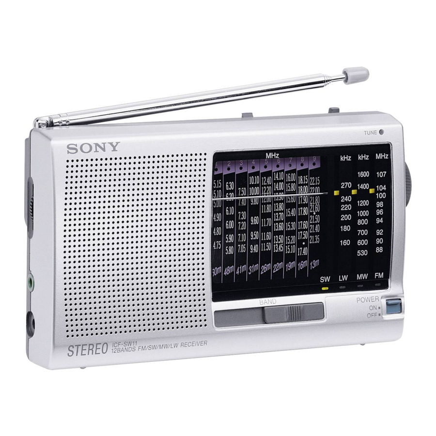
Sony SW11 - ICF Portable Radio Service Manual
Fm stereo/sw1-9/ mw/lw 12 band receiver
Hide thumbs
Also See for SW11 - ICF Portable Radio:
- User manual ,
- Operating instructions manual (19 pages) ,
- Service manual (16 pages)
Advertisement
SERVICE MANUAL
Ver 1.0 1999. 09
Frequency range:
FM:
87.5 – 108 MHz (Other models)
76 – 108 MHz (Tourist model)
SW1: 4.750 – 5.060 MHz (Other models)
3.850 – 4.050 MHz (Tourist model)
SW2: 5.900 –6.200 MHz
SW3: 7.100 – 7.350 MHz
SW4: 9.400 – 9.990 MHz
SW5: 11.600 – 12.100 MHz
SW6: 13.570 – 13.870 MHz
SW7: 15.100 – 15.800 MHz
SW8: 17.480 – 17.900 MHz
SW9: 21.450 – 21.750 MHz
MW:
525 – 1620 MHz
LW:
141 – 290 kHz
Speaker
Approx. 5.7 cm (2
Power output
140 mW (at 10 % harmonic distortion)
Ourput
Headphones jack (stereo minijack, 3.5 mm dia)
MICROFILM
SPECIFICATIONS
1
/
inches) dia., 4
4
ICF-SW11
Canadian Model
Power requirements
3 V DC, two R6 (size AA) batteries
DC IN 3V jack accepts : AC power adaptor
(Except chinese model)
AC-E30L, HG (not supplied)
Battery life
Approx. 30 hours with Sony SUM-3 (NS)
Dimensions
Approx. 162 93.8
1
3
3
(6
/
3
/
1
/
inches)
2
4
8
Mass
Approx. 340 g (12 oz) incl. batteries
Supplied accessory
Short wave guide (1)
Accessories not supplied
AC power adaptor
*AC-E3L, HG
LW/MW/SW wide range antenna AN-1, AN-102
*The voltage of power supply is different depending on the country .
Please buy an AC power adaptor in the country where the radio is
to be used.
Design and specifications are subject to change without notice.
FM STEREO/SW
MW/LW 12 BAND RECEIVER
US Model
AEP Model
E Model
Chinese Model
Tourist Model
34.8 mm(w/h/d)
/
1-9
Advertisement
Table of Contents

Summary of Contents for Sony SW11 - ICF Portable Radio
- Page 1 *The voltage of power supply is different depending on the country . Ourput Headphones jack (stereo minijack, 3.5 mm dia) Please buy an AC power adaptor in the country where the radio is to be used. Design and specifications are subject to change without notice.
-
Page 2: Table Of Contents
TABLE OF CONTENTS 1. GENERAL ·········································································· 3 2. DISASSEMBLY 2-1. Rear Cabinet ··································································· 4 2-2. Front Cabinet, Main Board ············································· 4 2-3. Dial Pointer Setting ························································· 5 3. ELECTRICAL ADJUSTMENT ···································· 6 4. DIAGRAMS 4-1. IC Block Diagram ··························································· 8 4-2. -
Page 3: General
SECTION 1 GENERAL BAND indicator BAND POWER select switch switch — 3 —... -
Page 4: Disassembly
SECTION 2 DISASSEMBLY Note : Follow the disassembly procedure in the numerical order given. 2-1. REAR CABINET 3 Three screws (P2.6 4 Two screws 2 Stand (P2.6 Claw 5 Cabinet (rear) (The cabinet is locked by the claws) 1 Lid, battery case 2-2. -
Page 5: Dial Pointer Setting
7 First, turn the tuning shaft fully in the arrow A direction. Move only the dial pointer in the arrow B direction and set it on the center of the scratched lines on the dial scale plate. Apply suitable locking compound to C portion. -
Page 6: Electrical Adjustment
• Preparation for SW band adjustment After making sure that the MW band adjustment has completed, set the pointer to the center of character of 6.0, 7.2, 11.8 or 21.6MHz which is reference position of dial character, and fix Headphones jack (J1) the CV1 at this position. -
Page 7: Diagrams
21.6MHz 1. Insert the plug to Headphones jack (J1). FM IF/ MPX REG. 2. Connect frequency counter to the positions shown the figure DISCRI 1. After completion of SW1-9 adjustment, confirm that each center right. frequency +910kHz signal is received from AM reference signal 3. -
Page 8: Printed Wiring Board
Ref. No. Location C-11 B-11 Note on Printed Wiring Board: D-10 • X : parts extracted from the component side. • b : Pattern from the side which enables seeing. • Abbreviation JE : Tourist model — 9 — — 10 —... -
Page 9: Schematic Diagram
• All resistors are in W or less unless otherwise ] : LW specified. • Voltages are taken with a VOM (Input impedance 10 M ). • : internal component. Voltage variations may be noted due to normal production • U : B+ Line. -
Page 10: Exploded Views
• CAPACITORS: • SEMICONDUCTORS have some differences from the original one. packing materials are given in the last of this parts list may be different from the parts uF: µF In each case, u: µ, for example: • Items marked “*” are not stocked since they parts list. - Page 11 4.7K 1/10W 1-216-115-00 METAL CHIP 560K 1/10W 1-566-891-11 JACK (HEADPHONE) 1-216-061-00 METAL CHIP 3.3K 1/10W 1-764-799-11 JACK, EXTERNAL POWER (DC IN 3V) 1-216-073-00 METAL CHIP 1/10W 1-216-025-91 RES,CHIP 1/10W < JUMPER RESISTOR > 1-216-073-00 METAL CHIP 1/10W 1-216-296-91 SHORT 0...
- Page 12 Remarks Ref. No. Part No. Description Remarks < VARIABLE RESISTOR > 1-228-995-00 RES, ADJ, METAL22K 1-238-555-11 RES, VAR, CARBON 50K < SWITCH > 1-692-846-11 SWITCH, SLIDE (BAND) 1-571-850-81 SWITCH, SLIDE (POWER) < TRANSFORMER > 1-416-021-11 COIL (AM IFT) ************************************************************ MISCELLANEOUS...


