D-Link DSL-2740B User Manual
Wireless adsl2+ router
Hide thumbs
Also See for DSL-2740B:
- User manual (111 pages) ,
- Quick installation manual (61 pages) ,
- Installation manual (10 pages)
Table of Contents
Advertisement
Advertisement
Table of Contents

Related Manuals for D-Link DSL-2740B


Summary of Contents for D-Link DSL-2740B
-
Page 1: User Guide
DSL-2740B Wireless ADSL2+ Router User Guide September 2006 ESL2740BEUA1G... -
Page 2: Ce Mark Warning
FCC Warning This device complies with part 15 of the FCC Rules. Operation is subject to the following two conditions: (1) This device may not cause harmful interference, and (2) this device must accept any interference received, including interference that may cause undesired operation. This equipment has been tested and found to comply with the limits for a Class B digital device, pursuant to part 15 of the FCC Rules. -
Page 3: Table Of Contents
Table Of Contents BEFORE YOU START ... V Installation Overview ...v Setup Wizard ...v Packing List...vi Installation Notes...vi INTRODUCTION ...1 Router Description and Operation ...1 Router Features ...2 Front Panel Display ...4 Rear Panel Connections...5 Setting Up a Wireless Network ...6 Location and Wireless Operation ...7 HARDWARE INSTALLATION ...8 Power on Router ...8... - Page 4 VIRTUAL SERVER ...50 PORT TRIGGERING ...51 DMZ ...53 OUTGOING IP FILTER ...54 INCOMING IP FILTER...56 BRIDGE FILTER ...57 PARENT CONTROL ...59 URL FILTER...60 QUALITY OF SERVICE ...61 ROUTING ...63 RIP...64 PORT MAPPING ...66 TOOLS ...69 BACKUP SETTINGS...70 UPDATE SETTINGS ...71 RESTORE DEFAULT...71 TR069 CLIENT ...72 SNMP CONFIGURATION ...73...
- Page 5 TECHNICAL SPECIFICATIONS ...95 CONFIGURING IP SETTINGS ON YOUR COMPUTER ...98 LOW PASS FILTERS FOR DSL ...104...
-
Page 6: About This User Guide
Note If you are using a computer with a functioning Ethernet port, the quickest and easiest way to set up the DSL-2740B is to insert the Installation CD into the CD-ROM drive of your computer and follow the instructions provided in the Quick Installation Guide. -
Page 7: Packing List
SSID to assign. These two settings must be the same for any wireless workstations or other wireless access point that communicate with the DSL-2740B through the wireless interface. -
Page 8: Information You Will Need From Your Adsl Service Provider
Security for wireless communication can be accomplished in a number of ways. The DSL-2740B supports WPA (Wi-Fi Protected Access), WPA2, and mixed WPA/WPA2. Wireless access can also be controlled by selecting MAC addresses that are allowed to associate with the device. Please read the section on Wireless Configuration. - Page 9 Router, you may choose among the numerous options available on the Modulation Type drop-down menu on the ADSL Configuration window (Advanced > ADSL) This is the method your ADSL service provider will use to Security Protocol verify your Username and Password when you log on to their network.
-
Page 10: Information You Will Need About Your Lan Or Computer
It is recommended that your collect and record this information here, or in some other secure place, in case you have to re-configure your ADSL connection in the future. Once you have the above information, you are ready to setup and configure your DSL-2740B Wireless ADSL Router. Record info here... -
Page 11: Introduction
This section provides a brief description of the Router, its associated technologies, and a list of Router features. Router Description and Operation The DSL-2740B Wireless ADSL Router is designed to provide connectivity for your private Ethernet LAN, and 802.11b/g/n-draft wireless LAN to the Internet via an ADSL connection. -
Page 12: Router Features
Router Features The DSL-2740B ADSL Router utilizes the latest ADSL enhancements to provide a reliable Internet portal suitable for most small to medium sized offices. DSL-2740B advantages include: • PPP (Point-to-Point Protocol) Security – The DSL-2740B ADSL Router supports PAP (Password Authentication Protocol) and CHAP (Challenge Handshake Authentication Protocol) for PPP connections. -
Page 13: Standards Compatibility And Compliance
Standards Compatibility and Compliance The DSL-2740B complies with or is compatible with the following standards as recognized by their respective agencies. • ITU G.992.1 (G.DMT) compliant • ITU G.992.2 (G.lite “Splitterless ADSL”) compliant • ITU-T Rec. I.361 compliant • RFC 791 Internet Protocol compliant •... -
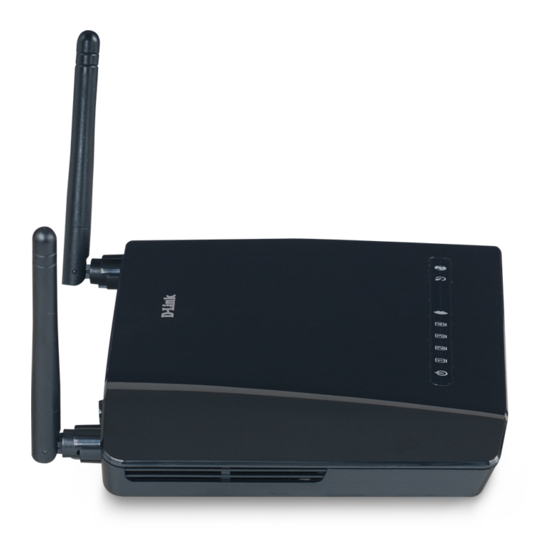
Page 14: Front Panel Display
Front Panel Display Place the Router in a location that permits an easy view of the LED indicators on the front panel. The LED indicators on the front panel include Power, LAN 1-4, WLAN, DSL, and Internet. The LAN, WLAN, and Internet indicators monitor link status and activity. -
Page 15: Rear Panel Connections
Ethernet devices To manually reboot the Router, disconnect and Note then reconnect the power. DSL-2740B Wireless ADSL Router User Guide Power insert Use the adapter shipped with the Router to connect to power source WARNING! Reset button To manually reset,... -
Page 16: Setting Up A Wireless Network
It will allow access to the wireless network to devices using the correct SSID after a negotiation process takes place. By default, the DSL-2740B broadcasts its SSID so that any wireless station in range can learn the SSID and ask permission to associate with it. Many wireless adapters are able to survey or scan the wireless environment for access points. -
Page 17: Location And Wireless Operation
With all this in mind, choose a location for all your access points including the DSL-2740B. The access point can be placed on a shelf or desktop, ideally you should be able to see the LED indicators on the front if you need to view them for troubleshooting. -
Page 18: Hardware Installation
Hardware Installation The DSL-2740B Wireless ADSL Router maintains three separate interfaces, an Ethernet LAN, a wireless LAN and an ADSL Internet (WAN) connection. Carefully consider the Router’s location suitable for connectivity for your Ethernet and wireless devices. You must have a functioning broadband connection via a bridge device such as a Cable or ADSL modem in order to use the Router’s WAN function. -
Page 19: Network Connections
Network Connections Wired network connections are provided through the ADSL port and the four Ethernet ports on the back of the Router. See the Rear Panel diagram above and the illustrations below for examples Connect ADSL Line Use the ADSL cable included with the Router to connect it to a telephone wall socket or receptacle. Plug one end of the cable into the ADSL port (RJ-11 receptacle) on the rear panel of the Router and insert the other end into the RJ-11 wall socket. -
Page 20: Computer To Router Connection
DSL-2740B Wireless ADSL Router User Guide Computer to Router Connection connect the Router directly to a 10/100BASE-TX Ethernet adapter card (NIC) installed on a PC using the Ethernet cable provided as shown in this diagram. - Page 21 DSL-2740B Wireless ADSL Router User Guide The illustration below shows the DSL-2740B connected to Ethernet LAN devices, Wireless LAN devices, and the Internet.
-
Page 22: Basic Router Configuration
Basic Router Configuration The first time you set up the Router it is recommended that you configure the ADSL (WAN) connection using a single computer making sure that both the computer and the Router are not connected to the LAN. Once the WAN connection is functioning properly, you may continue to make changes to Router configuration including IP settings and DHCP setup. -
Page 23: Access The Configuration Manager
Access the Configuration Manager In order to make sure your computer’s IP settings allow it to communicate with the Router, it is advisable to configure your system be a DHCP client – that is, it will get IP settings from the Router. Appendix B describes how to configure different Windows operating systems to “Obtain IP settings automatically”. -
Page 24: Configure The Router
DSL-2740B Wireless ADSL Router User Guide Configure the Router When you successfully connect to the web manager, the Home directory tab will display the Setup Wizard window. You can launch the Setup Wizard from this page or use the buttons located in the left panel of the web page to view other windows used for basic configuration. -
Page 25: Wizard
DSL-2740B Wireless ADSL Router User Guide All configuration and management of the Router is done using the web-based management interface pictured in the above example. The configuration windows are accessed by clicking on the directory tabs: Home, Advanced, Tools, and Status. Each tab has associated window buttons in the left hand panel of the web interface. Basic setup of the Router can be completed in the windows accessed from the Home directory including: (Setup) Wizard, WLAN, WAN (Internet), LAN (to configure the IP address of the Router), DNS and Dynamic DNS. - Page 26 DSL-2740B Wireless ADSL Router User Guide Click Next to go to the next Setup Wizard window. Using the Setup Wizard – WAN Settings - Choose Connection Type Now select the Connection Type used for the Internet connection. Your ISP has given this information to you. The connection types available are PPPoA, PPPoE, MER, IPoA and Bridge Mode.
- Page 27 DSL-2740B Wireless ADSL Router User Guide...
- Page 28 Using the Setup Wizard - For PPPoE/PPPoA connection: 1. Select the specific Connection Type and Encapsulation Mode. 2. Type in the Username and Password (and PPPoE Service Name, if required by your ISP) used to identify and verify your account to the ISP. 3.
- Page 29 Additional configurations available for PPP connection: PPP Connection Parameters Dial on demand PPP IP extension Use Static IP Address Enable PPP Debug Mode Description The Dial on demand function, if checked, will tear down the PPP link automatically when there is no incoming/outgoing packet via WAN interface for the programmed period of time that is set below (in minutes).
- Page 30 DSL-2740B Wireless ADSL Router User Guide Using the Setup Wizard - For Dynamic IP (1483 Bridge) connection: 1. Select the specific Connection Type and Encapsulation Mode. 2. Select Obtain an IP address/Default gateway/DNS server automatically. 3. Click Next to go to the next Setup Wizard window.
- Page 31 DSL-2740B Wireless ADSL Router User Guide Using the Setup Wizard - For Static IP Address (1483 Bridge) connection: 1. Select the specific Connection Type and Encapsulation Mode. 2. Enter the WAN IP Address, WAN Subnet Mask provided by your ISP.
- Page 32 DSL-2740B Wireless ADSL Router User Guide Using the Setup Wizard - For Static IP Address (IPoA) connection: 5. Select the specific Connection Type and Encapsulation Mode. 6. Enter the WAN IP Address, WAN Subnet Mask provided by your ISP. 7. Select Use the following default gateway/DNS server addresses and enter the ISP Gateway Address, Primary and Secondary DNS Server IP Address as instructed by your ISP.
- Page 33 Using the Setup Wizard - For Bridge Mode connections: 1. Select the specific Connection Type and Encapsulation Mode. 2. Click Next to go to the next Setup Wizard window. Using the Setup Wizard - For WAN Connection Settings: 1. Select the specific functions to be enabled. 2.
- Page 34 Using the Setup Wizard - For LAN Settings: You can configure the LAN IP address to suit your preference. Many users will find it convenient to use the default settings together with DHCP service to manage the IP settings for their private network. The IP address of the Router is the base address used for DHCP.
- Page 35 Using the Setup Wizard - For Wireless LAN Settings: Click the Enable Wireless box to allow the router to operate in the wireless environment. The SSID identifies members of the Service Set. Accept the default name or change it to something else. If the default SSID is changed, all other devices on the wireless network must use the same SSID.
- Page 36 DSL-2740B Wireless ADSL Router User Guide Using the Setup Wizard - Finish and Restart Finally you can confirm that the setup process is completed. If you are satisfied that you have entered all the necessary information correctly, click the Save/Reboot button to save the new configuration settings and restart the Router. If you need to change settings from a previous window, click the Back button.
-
Page 37: Adsl
DSL-2740B Wireless ADSL Router User Guide ADSL To access the ADSL (WAN) Settings window, click on the ADSL link button on the left side of the first window that appears when you successfully access the web manager. You can add, remove and edit the WAN interface from this page: To add a WAN connection, click the Add button and follow the step-by-step instruction as in WIZARD. -
Page 38: Atm Settings
Additional information for you to help you configure your WAN connections: ATM Settings: The ATM settings in the ADSL Settings windows for the different connection types can be used to adjust QoS parameters for ADSL clients. This may not be available to all ADSL accounts. ATM Parameters Virtual Circuit Service Category... -
Page 39: Router Settings
CDVT Router Settings: Parameters Default Route Firewall Primary DNS Address Secondary DNS Address by bursts of packets at variable intervals, and some moderate packet loss and delay is acceptable. This category is typically used for audio and video applications such as teleconferencing. The network must support QoS Class 2 to use VBR. -
Page 40: Wlan
DSL-2740B Wireless ADSL Router User Guide WLAN To access the WLAN Settings window, click on the WLAN link button on the left side of the first window that appears when you successfully access the web manager. WLAN Settings Window Click the Enable Wireless box to allow the router to operate in the wireless environment. -
Page 41: Lan
DSL-2740B Wireless ADSL Router User Guide The SSID identifies members of the Service Set. Accept the default name or change it to something else. If the default SSID is changed, all other devices on the wireless network must use the same SSID. - Page 42 DSL-2740B Wireless ADSL Router User Guide LAN Settings Window To change the LAN IP Address or Subnet Mask, type in the desired values and click the Save Settings button. You will be asked to reboot by a pop-up window. Click OK to reboot the router.
-
Page 43: Parameters Description
Parameters UPnP IGMP Snooping DHCP To manually configure IP settings on Windows workstations, open the TCP/IP Properties menu and select the “Use the following IP address” option. You will need to supply the IP addres, Subnet mask and Defualt Note gateway (use IP address of DSL- 2740B) for each workstation. -
Page 44: Dns
The Router can be configured to relay DNS settings from your ISP or another available service to workstations on your LAN. When using DNS relay, the Router will accept DNS requests from hosts on the LAN and forward them to the ISP’s, or alternative DNS servers. - Page 45 When you have configured the DNS settings as desired, click the Save Settings button.
-
Page 46: Advanced Router Management
Advanced Router Management Directory Setup Advanced Tools Status Configuration and Read-only Windows Click the Setup tab to access the Wizard, ADSL Settings, WLAN Settings, LAN Settings, and DNS Setup. See the previous chapter for a description of the Setup directory windows. Click the Advanced tab to access the Advanced ADSL, Advanced WLAN, WLAN Security, WLAN Filter, WLAN Bridge, WLAN QoS, Firewall Settings, Virtual Server, Port Trigering, DMZ, Outgoing/Incoming IP Filter, Bridge... -
Page 47: Advanced Adsl
Route, ARP, DHCP Clients, WLAN Station, and System Log. ADVANCED ADSL The ADSL Configuration window allows the user to set the configuration for ADSL protocols. For most ADSL accounts the default settings (ADSL2+) will work. This configuration works with all ADSL implementations. Do not change any settings unless you have been instructed. -
Page 48: Advanced Wlan
ADVANCED WLAN ADVANCED WLAN page allows you to tweek more advanced wireless settings. Most users will do just fine using default settings. Configure these parameters for your router: WLAN Parameters AP Isolation ADVANCED WLAN Window Description This is used to islolate wireless clients which connect to different APs. -
Page 49: Wlan Security
Channel 802.11 Mode Bandwidth 802.11n Rate Fragmentation Threshold RTS Threshold DTIM Interval Beacon Interval Preamble Type Transmit Power WLAN SECURITY In the WLAN Security window, select the type of security you want to configure. The window will change to present the settings specific to the method being configured. - Page 50 Click the Save Settings button to apply settings. Notice If encryption of any kind, at any level is applied to the Router, all devices on the network must comply with all security measures. 802.1x Some network-security experts now recommend that wireless networks use 802.1X security measures to overcome some weaknesses in standard WEP applications.
- Page 51 1. Select 802.1x from the Network Authentication drop-down list. 2. Enter your RADIUS server data: IP Address, Port, and Key. 3. Configure WEP Encryption. (See above section for detail.) 4. Click the Save Settings button to apply settings. WPA-PSK WPA-PSK configuration is similar to WEP. The key length is between 8 to 63 ASCII codes. WLAN SECURITY Window –...
- Page 52 WPA (Wi-Fi Protected Access) Wi-Fi Protected Access was designed to provide improved data encryption, perceived as weak in WEP, and to provide user authentication, largely nonexistent in WEP. To take full advanteage of WPA, a RADIUS server is needed in your network to authenticate users. For most home or SOHO users, WPA-PSK is the easiest way to implement and provides adequate protection for your wireless network.
-
Page 53: Wlan Filter
4. Click Save Settings to apply your settings. WLAN Filter The WLAN Filter is used to control wireless client devices access based on their MAC addresses. You can choose to allow or deny the specific MAC addresses. 1. Click the Add button to enter WLAN Filter configuration window. 2. -
Page 54: Wlan Bridge
WLAN FILTER Window WLAN BRIDGE Wireless bridge is used to bridge AP traffic between other APs. You can select Wireless Bridge (also known as Wireless Distribution System) to disables access point functionality. Selecting Access Point enables access point functionality. Wireless bridge functionality will still be available and wireless stations will be able to associate to the AP. - Page 55 Notice Wlreless Bridge function is available only when 802.11n is disabled. Please go to ADVANCED WLAN page to disable 802.11n before configuring Wireless Bridge. 1. Select AP Mode from the drop-down list. 2. Select Enabled in Bridge Restrict drop-down list and enter the MAC address of the AP which to be bridged. 3.
-
Page 56: Wlan Qos
WLAN QOS WLAN QoS (Quality of Service), also called WMM (Wi-Fi Multi-media), is used to prioritize the wireless packets when you are using wireles device transmitting delay-sensitive packets (voice, video,..etc). Notice WMM is not supported by IEEE 802.11n yet. You must trun off 802.11n in ADVANCED WLAN section before configuring any WMM settings. - Page 57 WLAN QoS Window (1) 4. Enter the name of the rule. 5. Select priority from the Wireless Transmit Priority drop-down list (1~4, higher number has higher priority). 6. Specify traffic classification rules. The classification can be de fined in the following parameters: Protocol, Source/Destination IP Address, and Source/Destination Port.
-
Page 58: Firewall
WLAN QoS Window (2) FIREWALL The Firewall Configuration window allows the Router to enforce specific predefined policies intended to protect against certain common types of attacks. There are two general types of protection (DoS, Port Scan) that can be enabled on the Router, as well as filtering for specific packet types sometimes used by hackers. -
Page 59: Firewall Window
traffic, attempts to disrupt connections between two machines, thereby preventing access to a service, attempts to prevent a particular individual from accessing a service, or, attempts to disrupt service to a specific system or person. Port scan protection is designed to block attempts to discover vulnerable ports or services that might be exploited in an attack from the WAN. -
Page 60: Virtual Server
LAN) traffic. The Virtual Server function allows remote users to access services on your LAN such as FTP for file transfers or SMTP and POP3 for e-mail. The DSL-2740B will accept remote requests for these services at your Global IP Address, using the specified TCP or UDP protocol and port number, and then redirect these requests to the server on your LAN with the LAN IP address you specify. -
Page 61: Port Triggering
1. Click the Add A Rule button to enter your virtual server configuration window. 2. Select a service from the drop down list for pre-configured server or select Custom Server to define your own server. 3. Enter your server IP address, protocol and port number. 4. - Page 62 Configure these parameters for port triggering on the router: Virtual Server Category Trigger Port Start/End Trigger Protocol Open Port Start/End PORT TRIGGERING Window Description Triggered port number initiated by local host Triggered protocol initiated by local host Opened port number(s) for remote users...
-
Page 63: Dmz
Open Protocol Opened protocol for remote users Since some applications are not compatible with NAT, the Router supports use of a DMZ IP address for a single host on the LAN. This IP address is not protected by NAT and will therefore be visible to agents on the Internet with the right type of software. -
Page 64: Outgoing Ip Filter
To designate a DMZ IP address, type in the IP Address of the server or device on your LAN in the DMZ Host IP Address box, and click the Save Settings button. To remove DMZ status from the designated IP address, clear the IP address in the box and click the Save Settings button. - Page 65 OUTGOING IP FILTER Window If more than one criterion is configured, all of them must be matched for this outgoing filter rule to take effect. Note...
-
Page 66: Incoming Ip Filter
INCOMING IP FILTER By default, all incoming packets are blocked if Firewall is enabled. But you can allow specific type of packets to be accepted by setting up incoming IP filter. 1. Click the Add A Rule button to enter your incoming IP filter configuration window. 2. -
Page 67: Bridge Filter
INCOMING IP FILTER Window BRIDGE FILTER Bridge filters are used to block or allow various types of packets through the WAN interface. This may be done for security or to improve network efficiency. The rules are configured for individual devices based on MAC address. Filter rules can be set up for source, destination or both. - Page 68 1. Click Chnage Policy button to change bridge filter policy between Forwarded and Blocked. 2. Click the Add A Rule button to enter your bridge filter configuration window. 3. Select Protocol Type from the drop-down list, or leave it blank for all protocols. 4.
-
Page 69: Parent Control
PARENT CONTROL Parent control is used to prevent specific local hosts from accessing Internet based on their MAC address. 1. Click the Add A Rule button to enter your parent control configuration window. 2. Enter the user name and MAC address of the restricted PC. 3. -
Page 70: Url Filter
Local host’s MAC address will be displayed automatically when enter this configuration page. To find out other PC’s MAC address. Open the specific PC’s command prompt window, type command ipconfig /all and check Physical Note Address row. URL FILTER URL filter is used to control Internet website access. You can decide that your local hosts can access these specific websites only, or can not access these websites only. -
Page 71: Quality Of Service
URL FILTER Window QUALITY OF SERVICE QoS (Quality of Service) is a traffic class rule to classify the upstream traffic, assign queuing priority and optionally overwrite the IP header TOS byte. This is to ensure that the delay-sensitive traffic has higher priority to go to Internet. IP Precedence and IP TOS (Type of Service) marking, once enabled, will overwrite the correspondent TOS byte in the IP haeder. - Page 72 2. Enter the name of the rule. 3. Assign ATM priority from the Assign ATM Transmit Priority drop-down list. 4. Check Enable Differentiated Service Configuration box if it is supported by your ISP. 5. Select the optional marking on IP Precedence and TOS from the Mark IP Precedence and Mark IP Type Of Service drop-down lists.
-
Page 73: Routing
All of the specified conditions in this classification rule must be satisfied for the rule to take effect. To delete the configured QoS rule, check the box in Remove field and click Remove button on top. ROUTING Use Static Routing to specify a route used for data traffic within your Ethernet LAN or to route data on the WAN. This is used to specify that all packets destined for a particular network or subnet use a predetermined gateway. -
Page 74: Rip
The Router supports RIP v1 and RIP v2 used to share routing tables with other Layer 3 routing devices on your local network or remote LAN. 1. Click the Enabled radio button to enable the router RIP function. 2. Select RIP Version and Operation mode from the drop-down list. ROUTING Window... - Page 75 3. Check Enabled box and click Save Settings to apply your settings. To disable RIP, click Disabled radio button and click Save Settings. RIP Window More on RIP settings: RIP Parameters Description...
-
Page 76: Port Mapping
Interface Version Operation PORT MAPPING Port Mapping supports multiple ports to PVC and bridging groups. Each group will perform as an independent network. To support this feature, you must create mapping groups with appropriate LAN and WAN interfaces. By default, all interfaces are included in the Default group. - Page 77 PORT MAPPING Window (1) 2. Click Add button to enter port mapping configuration window. 3. Enter the group name and select the specific interfaces from Available Interfaces (Default group) to Grouped Interfaces. 4. Click Save Settings to apply your settings.
- Page 78 PORT MAPPING Window (2)
-
Page 79: Tools
TOOLS Click the Tools tab to reveal the window buttons for various functions located in this directory. The Diagnostics window is the first item in the Tools directory. The Diagnostic Test window is used to test connectivity of the Router. A Ping test may be done through the local or external interface to test connectivity to known IP addresses. -
Page 80: Backup Settings
BACKUP SETTINGS Once you have configured the Router to your satisfaction, it is a good idea to back up the configuration file to your computer. To save the current configuration settings to your computer, click the Backup Settings button in the Tools directory to display the window. -
Page 81: Update Settings
UPDATE SETTINGS To load a previously saved configuration file, click the Browse button and locate the file on your computer. Click the Update Settings button to load settings from local hard drive. Confirm that you want to load the file when prompted and the process is completed automatically. -
Page 82: Tr069 Client
TR069 CLIENT TR-069 is a WAN Management Protocol which allows an Auto-Configuration Server (ACS) to perform auto- configuration, provision, collection, and diagnostics to this device. You should have all the necessary information frm your ISP if TR-069 is implemented by your ISP. 1. -
Page 83: Snmp Configuration
3. Click Save/Apply to apply your settings. SNMP CONFIGURATION Simple Network Management Protocol is a standard for internetwork and intranetwork management. Please contact your ISP for all necessary information before configuring SNMP. 1. Click Enable radio button in SNMP Agent. 2. -
Page 84: Ddns
3. Click Save/Apply to apply your settings. SNMP CONFIGURATION Window DDNS The Router supports DDNS (Dynamic Domain Name Service). The Dynamic DNS service allows a dynamic public IP address to be associated with a static host name in any of the many domains, allowing access to a specified host from various locations on the Internet. - Page 85 specific host on the LAN using standard DNS. If for example you are running a public web server or VPN server on your LAN, this ensures that the host can be located from the Internet if the public IP address changes. DDNS requires that an account be setup with one of the supported DDNS service providers (DyndDNS.org or TZO).
-
Page 86: Time
Configure these parameters for DDNS: DDNS Parameters DDNS Server Host Name Interface Username (or Key) Password (or Key) Email (if used) TIME The Router provides you a method (Network Time Protocol) to maintain your router system clock via Internet. 1. Select Automatically synchronize with Internet time servers. 2. -
Page 87: Access Service
TIME Window ACCESS SERVICE You can select to enable or disable of which management services from being used in your router, for LAN and/or WAN interface. You need configure at least one WAN interface (except Bridge) before settings up service control list on WAN interface. - Page 88 2. Click the Save/Apply button to apply your settings. CAUTION: If you disable HTTP service, you’ll not be able to access the router’s configuration window permanently. ACCESS SERVICE Window...
-
Page 89: Access Ip
ACCESS IP The IP Address Access Control mode, if enabled, permits access to local management services from IP addresses contained in the Access Control List. The available management services are configured in the Access Service. 1. Click Add button to enter access IP address configuration window. 2. -
Page 90: Password
ACCESS IP Window PASSWORD Access to your router is controlled through three user accounts: admin, support, and user. The user name admin has unrestricted access to change and view configuration of your router. The user name support is used to allow an ISP technician to access your router for maintenance and to run diagnostics. -
Page 91: Update Firmware
UPDATE FIRMWARE Use the Firmware Upgrade window to load the latest firmware for the device. Note that the device configuration settings may return to the factory default settings, so make sure you save the configuration settings with the System Settings window described above. To upgrade firmware, click on the Browse button to search for the file. - Page 92 SAVE / REBOOT Window...
-
Page 93: Status
STATUS Use these windows to view system information and monitor performance. DEVICE INFO Use the Device Information window to quickly view basic current information about the router and device information including Firmware Version and ADSL connection status. DEVICE INFO window... -
Page 94: Adsl
ADSL This window displays ADSL information including Link Rate, SNR, and some Error Counters. ADSL Window This window displays LAN information including IP address, Mask, and DCHP pool. -
Page 95: Wan
LAN Window This window displays WAN information including IP address, Mask, Dafault Gateway, Primary/Secondary DNS Server. -
Page 96: Atm
WAN Window This window displays ATM information including Cell Count and someError Counters. -
Page 97: Route
ATM Window ROUTE This window displays the Routing Table of the router. -
Page 98: Arp
ROUTE Window This window displays ARP Table of the router’s LAN port. -
Page 99: Dhcp Clients
ARP Window DHCP CLIENTS This window displays all the client devices which have obtained IP addresses from the router. -
Page 100: Wlan Station
DHCP CLIENTS window WLAN STATION This window displays authenticated wireless stations and their status. -
Page 101: System Log
WLAN STATION Window SYSTEM LOG The system log displays chronological event log data. The event log can be read from local host or sent to syslog server. The available event severity levels are: Emergency, Alert, Critical, Error, Warning, Notice, Informational and Debugging,... - Page 102 SYSTEM LOG window (1) 1. Click Configure System Log button to enter system log configuration window. 2. Click Enable radio button and select Log/Display Level from the drop down list. 3. Select display mode from the Mode drop-down list; enter the syslog server IP address and port number if Both/Remote Mode is selected.
- Page 103 Log Level Display Level Mode Server IP Address Server UDP Port All events above or equal to the selected level will be logged. All logged events above or equal to the selected level will be displayed. Display mode of system log. Local: Display on local host only •...
- Page 104 SYSTEM LOG window (2)
-
Page 105: Technical Specifications
Technical Specifications General ADSL Standards • • Standards: • • • • • • • Protocols: • • • • • • • Data Transfer Rate: • • • Media Interface: • ANSI T1.413 Issue 2 ITU G.992.1 (G.dmt) AnnexA ITU G.992.2 (G.lite) Annex A ITU G.994.1 (G.hs) ITU G.992.5 Annex A... -
Page 106: Power Adapter
Physical and Environmental DC Inputs: Input: 120V AC 60Hz Output: 12V AC, 1200mA Power Adapter: Power 12 Watts (max) Consumption: Operating 0° to 40°C Temperature: Storage -20° to 70°C Temperature Humidity: 5% to 95% (non-condensing) Dimensions: 109 mm x 142.8 mm x 32.1 mm Weight: 200 gm EMI:... -
Page 107: Media Interface
Wireless Modulation Frequency Channels Wireless Data Rates Media Access Protocol Wireless Certification ADSL Data Rates Media Interface IEEE 802.11b: DQPSK, DBPSK, DSSS, and CCK IEEE 802.11g: BPSK, QPSK, 16QAM, 64QAM, OFDM 2400 ~ 2484.5MHz ISM band 11 channels for United States 13 channels for European Countries 13 channels for Japan IEEE 802.11b: 11, 5.5, 2, and 1Mbps... -
Page 108: Configure Windows Xp For Dhcp
Configuring IP Settings on Your Computer In order to configure your system to receive IP settings from the Router it must first have the TCP/IP protocol installed. If you have an Ethernet port on your computer, it probably already has TCP/IP protocol installed. If you are using Windows XP the TCP/IP is enabled by default for standard installations. - Page 109 Click Network and Internet Connections. In the Network and Internet Connections window, click Network Connections. Click Network Connections. 4. In the Network Connections window, right-click on Local Area Connection, then click Properties. Right-click Local Connection icon select Properties option from the pull-down menu.
- Page 110 5. In the General tab of the Local Area Connection Properties window, highlight Internet Protocol (TCP/IP) under “This connection uses the following items:” by clicking on it once. Click on the Properties button. Click Properties. 6. Select “Obtain an IP address automatically” by clicking once in the circle. Click the OK button Your computer is now ready to use the Router’s DHCP server.
-
Page 111: Windows 2000
Windows 2000 First, check for the IP protocol and, if necessary, install it: 1. In the Windows task bar, click the Start button, point to Settings, and then click Control Panel. 2. Double-click the Network and Dial-up Connections icon. 3. In the Network and Dial-up Connections window, right-click the Local Area Connection icon, and then select Properties. -
Page 112: Windows 95 And Windows 98
Windows 95 and Windows 98 First, check for the IP protocol and, if necessary, install it: 1. In the Windows task bar, click the Start button, point to Settings, and then click Control Panel. Double-click the Network icon. 2. The Network dialog box displays with a list of currently installed network components. If the list includes TCP/IP, and then the protocol has already been enabled, skip to Configure IP Information Windows 95, 98. - Page 113 Your computer is now ready to use the Router’s DHCP server. Windows NT 4.0 Workstations First, check for the IP protocol and, if necessary, install it: 1. In the Windows NT task bar, click the Start button, point to Settings, and then click Control Panel. 2.
-
Page 114: Low Pass Filters For Dsl
Low Pass Filters for DSL Most ADSL clients will be required to install a simple device that prevents the ADSL line from interfering with regular telephone services. These devices are commonly referred to as microfilters or low pass filters. The two basic styles of low pass filters commonly used are described below. -
Page 115: Port Filter
Three Port Filter Another style of filter is installed at the same point where the Router connects to the telephone line. Only a single filter is required. The connection ports are typically labeled as follows: Line - This port connects to the wall jack. ADSL –...