Advertisement
Table of Contents
This manual has been provided for the use of authorized YAMAHA Retailers and their service personnel.
It has been assumed that basic service procedures inherent to the industry, and more specifically YAMAHA Products, are already
known and understood by the users, and have therefore not been restated.
WARNING:
IMPORTANT:
The data provided is believed to be accurate and applicable to the unit(s) indicated on the cover. The research, engineering, and
service departments of YAMAHA are continually striving to improve YAMAHA products. Modifications are, therefore, inevitable
and specifications are subject to change without notice or obligation to retrofit. Should any discrepancy appear to exist, please
contact the distributor's Service Division.
WARNING:
IMPORTANT:
I CONTENTS
TO SERVICE PERSONNEL .......................................... 2
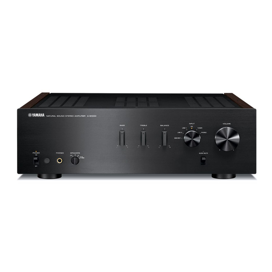
FRONT PANEL .............................................................. 3
REAR PANELS .......................................................... 3-6
REMOTE CONTROL PANELS ...................................... 6
SPECIFICATIONS /
参考仕様
INTERNAL VIEW ........................................................... 8
サービス時の注意事項 .................................................... 9
DISASSEMBLY PROCEDURES /
AMP ADJUSTMENT /
UPDATING FIRMWARE /
ファームウェアの書き込み ..................................... 20-25
1 0 1 0 9 1
STEREO AMPLIFIER
A-S1000
Failure to follow appropriate service and safety procedures when servicing this product may result in personal
injury, destruction of expensive components, and failure of the product to perform as specified. For these reasons,
we advise all YAMAHA product owners that any service required should be performed by an authorized
YAMAHA Retailer or the appointed service representative.
The presentation or sale of this manual to any individual or firm does not constitute authorization, certification or
recognition of any applicable technical capabilities, or establish a principle-agent relationship of any form.
Static discharges can destroy expensive components. Discharge any static electricity your body may have
accumulated by grounding yourself to the ground buss in the unit (heavy gauge black wires connect to this buss).
Turn the unit OFF during disassembly and part replacement. Recheck all work before you apply power to the unit.
.......................................... 7
............. 9-18
............................. 19
Copyright © 2008
This manual is copyrighted by YAMAHA and may not be copied or
redistributed either in print or electronically without permission.
SERVICE MANUAL
IMPORTANT NOTICE
ダイアグ(自己診断機能) ..................................... 26-28
IC DATA ................................................................. 29-32
PIN CONNECTION DIAGRAMS ............................ 33-34
BLOCK DIAGRAM ....................................................... 35
PRINTED CIRCUIT BOARDS ................................ 36-54
SCHEMATIC DIAGRAMS ...................................... 55-61
REPLACEMENT PARTS LIST .............................. 63-83
REMOTE CONTROL .............................................. 84-85
All rights reserved.
P.O.Box 1, Hamamatsu, Japan
'08.05
Advertisement
Table of Contents

Related Manuals for Yamaha AS1000BL


Summary of Contents for Yamaha AS1000BL
-
Page 1: Table Of Contents
The data provided is believed to be accurate and applicable to the unit(s) indicated on the cover. The research, engineering, and service departments of YAMAHA are continually striving to improve YAMAHA products. Modifications are, therefore, inevitable and specifications are subject to change without notice or obligation to retrofit. -
Page 2: To Service Personnel
Avoid prolonged, unprotected contact between solder and your skin! When soldering, do not inhale solder fumes or expose eyes to solder/flux vapor! If you come in contact with solder or components located inside the enclosure of this product, wash your hands before handling food. - Page 7 PHONO (0.003 % THD) MM ........120 mV or less Accessories / 付属品 MC ........7 mV or less Remote control x 1, Battery (R6, AA, UM-3) x 2, Power cable (2 m) x 1 Frequency Response / 周波数特性 CD, etc.
- Page 8 A-S1000 I INTERNAL VIEW Top view 1 FRONT (14) P.C.B. (R, L models) 2 FUNCTION (3) P.C.B. 3 FRONT (13) P.C.B. 4 MAIN (2) P.C.B. 5 FUNCTION (2) P.C.B. 6 POWER TRANSFORMER 7 MAIN (3) P.C.B. 8 MAIN (1) P.C.B.
-
Page 9: Front Panel
AC電源コンセントから、電源コードを抜いてください。 Hook 1. パネルサイド L/Rの外し方 フック 1. Removal of Panel Side L/R a. Remove 2 screws (1), 2 coned disc spring L and 2 a. 1のネジ2本を外し、サラバネL2個とワッシャーサイド washers side. (Fig. 1) 2個を外します。 (Fig. 1) Coned disc spring L b. Lift the panel side L upward and release 3 hooks. Then b. - Page 10 す。 Knob SEL unit スリット ノブVOLユニット ノブSELユニット b. Match the slit in the knob TC unit with the center b. ノブTCユニットのスリットをBALANCE中央の position of BALANCE and install it in that state. 位置に合わせ、取り付けます。 (Fig. 2) (Fig. 2) ※ このとき、まだ止めネジは締めません。...
- Page 11 A-S1000 4. フロントフレームASSYの外し方 4. Removal of Front Frame Ass’y a. 7 のネジ4本を外し、フレームトップを取り外します。 a. Remove 4 screws (7) to remove the frame top. (Fig. 3) b. Remove 8 screws (8). (Fig. 3) (Fig. 3) b. 8 のネジ8本を外します。 (Fig. 3) c. Remove CB501, CB504, CB517, CB519, CB521 and SW1-2.
- Page 12 に接続されています。フロントフレームA S S Y を disconnected. シャーシより取り外した場合は、アース線等でシャー • In this unit, the ground of the front frame ass’y is con- シに接続してください。 (Fig. 4) nected to the chassis. When the front frame ass’y is removed from the chassis, connect the ground point to the chassis, using a ground lead wire or the like.
- Page 13 5. アンプユニットL/Rの外し方 5. Removal of Amplifier Unit a. 9 のネジ8本、 0 のネジ2本を外します。 (Fig. 5) a. Remove 8 screws (9) and 2 screws (0). (Fig. 5) b. Remove the frame side L. (Fig. 5) b. フレームサイドLを取り外します。 (Fig. 5) c. A のネジ4本を外します。 (Fig. 5)...
- Page 14 G When installing the power unit: ● パワーユニットを取り付ける場合: When installing the power unit, be very careful not パワーユニットを取り付ける場合、ネジの先端で底 面のケーブルにキズ等付けないよう十分注意してく to cause any damage to the cable at the bottom with the end of the screw. (Fig. 6) ださい。 (Fig. 6) Bottom view Cable ケーブル...
- Page 15 Reconnect all cables (connectors) that have been 続されています。アンプユニットL/Rをシャーシより disconnected. 取り外した場合は、アース線等でシャーシに接続して • In this unit, the ground of the amplifier unit L/R is ください。 (Fig. 7) connected to the chassis. When the amplifier unit L/R ・ アンプユニットL/Rは底面からチェックすることもで is removed from the chassis, connect the ground きます。...
- Page 16 7. FUNCTION (2) P.C.B.の外し方 7. Removal of FUNCITON (2) P.C.B. a. F のネジ4本、 G のネジ1本を外します。 (Fig. 8) a. Remove 4 screws (F) and screw (G). (Fig. 8) b. Remove CB401-404, CB407 and CB408. (Fig. 8) b. CB401-404、CB407、CB408を外します。 (Fig. 8) c. TRコネクターを外します。 (Fig. 8)...
- Page 17 8. スピーカーターミナルL/Rの外し方 8. Removal of Speaker Terminal L/R a. H のネジ2本、 I のネジ2本を外します。 (Fig. 8) a. Remove 2 screws (H) and 2 screws (I). (Fig. 8) b. CB2、CB23、CB79を外します。 (Fig. 8) b. Remove CB2, CB23 and CB79. (Fig. 8) c. Remove FUNCTION (3) P.C.B.. (Fig. 8) c.
- Page 18 9. Removal of FUNCTION (1) P.C.B. and FRONT の外し方 (10) P.C.B. a. Q のネジ9本、 R のネジ1本、 S のネジ2本を外しま a. Remove 9 screws (Q), a screw (R), and 2 screws (S). す。 (Fig. 10) (Fig. 10) b. CB302、CB305を外します。 (Fig. 10) b. Remove CB302 and CB305. (Fig. 10) c.
-
Page 19: アンプ部調整
Precaution for handling measuring instrument The ground side of the measuring instrument to be con- 本機はフローティングバランスパワーアンプを搭載して いるので、本機のスピーカー出力端子に接続する計測器 nected to the speaker terminal of this unit must be kept in DC +4.0 to +8.0 mV floating condition because this unit is equipped with the のアース側はフローティング状態にする必要がありま... - Page 20 3. RS232C変換アダプターのスイッチ (SW301) を • Windows 98/2000/Me/XP, PC with a serial port ・ W i n d o w s 9 8 / 2 0 0 0 / M e / X P 、シリアルポート (RS232C) (RS232C) 付きPC adapter to the “FLASH UCOM” side. (Fig. 1) “FLASH UCOM”...
- Page 21 A-S1000 5. Connect the power cable of this unit to the AC out- 5. 本機の電源コードをACコンセントに接続します。 let. At this time, set the “POWER ON/OFF” switch このとき、 “POWER ON/OFF” スイッチはOFFに します。 to the OFF position. 6. Start up “FlashSta.exe”. 6. “FlashSta.exe” を起動します。...
- Page 22 れます。 (Fig. 4) Click [OK]. (Fig. 4) [OK] をクリックします。 (Fig. 4) When [Refer...] is clicked, the open file screen is displayed. [R e f e r . . . ] をクリックすると “ファイルを開く” が表示されま す。 Select the firmware “A-S1000.s2”. ファームウェア “A-S1000.s2” を選択します。...
- Page 23 15. 書き込み完了後、 “Program OK.” が表示されます。 Click [OK]. (Fig. 5) (Fig. 5) [OK] をクリックします。 (Fig. 5) 16. Set the “POWER ON/OFF” switch to the OFF po- sition. 16.“POWER ON/OFF” スイッチをOFFにします。 17. Disconnect the power cable of this unit from the 17. 本機の電源コードをACコンセントから抜きます。...
-
Page 24: Self-Diagnostic Function
"TREBLE" knob "BALANCE" knob Fig. 6 Input selector LED / Firmware version / INPUTセレクターLED ファームウェアバージョン Binary number (BCD) [Lit: 1, Off: 0] / 2進数 (BCD) [ 点灯:1、消灯:0] MAIN DIRECT LINE 2 LINE 1 TUNER PHONO Decimal number / 10進数 = 32) - Page 25 "POWER ON/OFF" switch to the OFF” スイッチをONにします。 (Fig. 7) 2. INPUTセレクターLED “CD” が点灯し、通常動作 ON position. (Fig. 7) 2. The INPUT selector LED “CD” will light up and the に戻ります。 (Fig. 7) normal operation will be restored. (Fig. 7) 3. “POWER ON/OFF” スイッチをOFFにして終了し...
- Page 26 A-S1000 I SELF-DIAGNOSTIC FUNCTION / ダイアグ (自己診断機能) G Protection Information Display ● プロテクション情報の表示 When the power to this unit is turned on and the power 本機に電源を投入してPOWERインジケーターが点滅 表示している場合、プロテクションが動作しているた indicator is flashing, the normal operation is not avail- able because the protection function is at work.
- Page 27 :電源トランスのC B 2 1 、C B 2 2 、 Detected at : CB21, CB22 and CB23 of power C B 2 3 、F U N C T I O N P . C . B . の transformer, +18V, +12C of +18V、+12C、FRONT P.C.B.の...
- Page 28 L/Rch, it is not possible to start this unit with ることができません。 the protection function cancelled. プロテクションが動作することにより、故障箇所の診 If the protection function works and causes hindrance to trouble shoot, it will be possible to start this unit in 断に支障をきたすような場合は、次の方法によりプロ テクションを解除した状態で本機を起動させることが the protection cancel mode by following procedures. できます。...
- Page 29 5 6 7 8 9 10 11 13 14 15 16 17 18 19 21 22 23 24 25 28 29 57 58 59 60 61 62 63 64 34 35 36 37 38 39 40 42 43 44 45 46 47 48...
- Page 30 Power relay control P4-3/INT2 RY_PWR Power detect, Hi at AC ON / [Pull-up] P4-2/INT1 PWR_DET Normal operation / Write mode select, P4-6: H, set to Boot mode with settings of CNVSS CNVSS P4-5: H and CNVSS: H / [4.7k pull-down] /RESET /RESET...
- Page 31 AVSS AVSS P6-7/AN7 PRV1 Power amp DC protect detect P6-6/AN6 EX_DI Data in for extend IC / LC709004A / Max 2MHz when using VDD=4.5 to 6V Head phone DC protect detect P6-5/AN5 HP_PRDL Head phone DC protect detect P6-4/AN4 HP_PRDR...
- Page 32 Treble control SW_BAS Bass control Initial clear extended IC – I_HP Detect head phone insert, H: HP non inserted / L: HP inserted I_SW_BAL_GAIN Balance gain select SW I_MUTE Detect switch for MUTE I_MMMC Detect switch MMMC, Hi: MC / Low: MM...
-
Page 33: Pin Connection Diagrams
A-S1000 I PIN CONNECTION DIAGRAMS • BA15218F LB1641 LC709004A-TLM-E LM61CIZ LME49723MA M38039xxxxx NE5532DR NJM2068MD-TE2 NJM2082M-TE1 NJM7812FA 3: IN 1: OUT 2: COM NJM7912FA RH5RE58AA-T1-FA TC94A81UG TC74HC4051AFEL 1: Vin 1: COMMON 2: GND 2: INPUT 3: Vout 3: OUTPUT • Diodes... - Page 34 A-S1000 • Transistors 2SA970 2SA1036K 2SA1037K 2SA1708 2SA1145 2SC2240 2SC4488 2SC2705 2SD1938F 2SC2878 2SA1312-GR,BL 2SA2168 2SA2180 ST 2SC1740S 2SC1846 S 2SC2412K 2SC5291 2SC6081 ST 2SC3324-GR,BL 2SC3852 2SK208-Y 2SK209 2SC4468 O,P,Y 2SK369 5HP01C-TB-E DTA144EKA KRA104S-RTK DTC114EKA KRC104S-RTK DTC144EKA 1: GND COMMON...
-
Page 35: Block Diagram
A-S1000 I BLOCK DIAGRAM • See page 59-61 → • See page 55-57 → • See page 59-61 → VOLUME & TONE CONTROL FRONT FUNCTION FRONT SCHEMATIC DIAGRAM SCHEMATIC DIAGRAM SCHEMATIC DIAGRAM FLOATING BALANCED IC410 POWER AMPLIFIER IC404 ATT.1 TONE CONTROL DEVICES... -
Page 36: Printed Circuit Boards
RY_SPB+ FRONT (1) -12C (CB519) • Semiconductor Location FUNCTION (2) FRONT (10) (CB408) (W1003) Ref no. Location Ref no. Location Ref no. Location Ref no. Location Ref no. Location FUNCTION (3) FUNCTION (2) (W3) D3001 IC303 Q3007 Q3039 Q3052 (CB403) - Page 37 A-S1000 FUNCTION (1) P.C.B. (Side B) • Semiconductor Location Ref no. Location Ref no. Location Ref no. Location D3006 D3026 D3046 D3007 D3027 D3047 D3008 D3028 D3048 D3009 D3043 D3049 D3010 D3044 D3050 D3011 D3045 D3051...
- Page 38 A-S1000 • Semiconductor Location Ref no. Location Ref no. Location Ref no. Location Ref no. Location Ref no. Location Ref no. Location Ref no. Location Ref no. Location Ref no. Location Ref no. Location D4009 D4026 D4040 D4066 Q4012 Q4021...
- Page 39 A-S1000 FUNCTION (2) P.C.B. (Side B) • Semiconductor Location Ref no. Location Ref no. Location Ref no. Location Ref no. Location D4012 D4022 D4031 Q4002 Q4008 D4014 D4023 D4032 Q4010 D4015 D4028 D4045 Q4011 D4016 D4030 D4046...
- Page 40 A-S1000 FRONT (1) (CB501) FUNCTION (3) P.C.B. (Side A) U, C, T, K, A, B, G, J models R, L models CB25 MAIN (3) (W317) CB23 POWER TRANSFORMER R, L models POWER ON/OFF PRMSW1 switch PRMSW2 FRONT (14) IC51 (W8A, W8B)
- Page 41 A-S1000 FUNCTION (3) P.C.B. (Side B) R, L models • Semiconductor Location Ref no. Location R, L models...
- Page 42 CB58 CB57 RSP_P RSP_N CB60 CB59 FRONT (12) (W101A, W101B) • Semiconductor Location MAIN (4) P.C.B. (Side A) Ref no. Location Ref no. Location Ref no. Location Ref no. Location D101 D109 Q105 Q117 D102 D115 Q106 Q122 D103 D124...
- Page 43 A-S1000 MAIN (1) P.C.B. (Side B) MAIN (4) P.C.B. (Side B) • Semiconductor Location Ref no. Location D122 D123 Q114 Q118...
- Page 44 CB78 CB77 LSP_P LSP_N CB80 CB79 FRONT (13) (W201A, W201B) MAIN (5) P.C.B. (Side A) • Semiconductor Location Ref no. Location Ref no. Location Ref no. Location Ref no. Location D125 D208 Q205 Q217 D201 D209 Q206 Q222 D202 D215...
- Page 45 A-S1000 MAIN (2) P.C.B. (Side B) MAIN (5) P.C.B. (Side B) • Semiconductor Location Ref no. Location D222 D223 Q214 Q218...
- Page 46 ・ 下記箇所には電源をOFFにした後も電荷が残り、高電圧が維持されており危険です。修理作業前に放電用抵抗 (5 kΩ/10 W) • Note that positions indicated below are dangerous even after the power is turned off because an electric charge remains and a high を下記箇所の端子間に接続して放電してください。放電所用時間は約30秒間です。 1. MAIN (3) P.C.B.のC308 voltage continues to exist there. Before starting any repair work, perform discharge by connecting a discharge resistor (5k-ohms/ 2.
- Page 47 A-S1000 MAIN (3) P.C.B. (Side B) • Semiconductor Location Ref no. Location D309 D310 D329 D330 Q300 Q301 Q302 Q318 Q322...
- Page 48 BALANCE TREBLE BASS W5002 FRONT (9) P.C.B. PDET /RES (Side A) RY_PWR +12C DGND FUNCTION (3) POINT A-2 1 / Pin 1, 2 / Pin 3 of CB501 -12C (W1) POWER RY_SPA indicator RY_SPB PSAV1 PSAV2 W5009A W5003A W5008 W5005A...
- Page 49 A-S1000 FRONT (1) P.C.B. (Side B) FRONT (2) P.C.B. (Side B) FRONT (3) P.C.B. (Side B) • Semiconductor Location FRONT (9) P.C.B. (Side B) Ref no. Location Ref no. Location D5004 Q5013 D5011 Q5014 D5012 Q5015 D5013 Q5016 D5014 Q5019...
- Page 50 A-S1000 FRONT (4) P.C.B. (Side A) FRONT (5) P.C.B. (Side A) FRONT (6) P.C.B. (Side A) INPUT indicator VOLUME INPUT MAIN DIRECT LINE2 LINE1 FRONT (3) LED_MT (W5005A) LED_MDIR LED_CD I_ISEL FRONT (1) LED_L2 LED_L1 (W5006) LED_PHO TUNER LED_TU DGND...
- Page 51 A-S1000 FRONT (4) P.C.B. (Side B) FRONT (5) P.C.B. (Side B) FRONT (6) P.C.B. (Side B) FRONT (11) P.C.B. (Side B) FRONT (7) P.C.B. (Side B) • Semiconductor Location Ref no. Location D345 D346 D5026 Q305 Q306...
- Page 52 A-S1000 • Semiconductor Location Ref no. Location Ref no. Location Ref no. Location Ref no. Location Ref no. Location Ref no. Location FRONT (10) P.C.B. (Side A) D1003 D1009 Q1014 Q1024 Q1032 Q1038 D1004 Q1009 Q1015 Q1025 Q1033 Q1039 D1005...
- Page 53 A-S1000 • Semiconductor Location FRONT (10) P.C.B. (Side B) Ref no. Location Ref no. Location Ref no. Location Ref no. Location Q1020 D1001 D1013 Q1005 Q1021 D1002 Q1001 Q1006 Q1022 D1010 Q1002 Q1007 Q1029 D1011 Q1003 Q1008 Q1030 D1012 Q1004...
- Page 54 RSP_P FUNCTION (3) W12C FUNCTION (3) (CB2) W12E (W4) W12B W12G W12A K, B, G models K, B, G models POWER TRANSFORMER • Semiconductor Location Ref no. Location D122 D123 FRONT (12) P.C.B. FRONT (13) P.C.B. (Side B) (Side B) FRONT (14) P.C.B.
- Page 55 FUNCTION (1) # All voltages are measured with a 10MΩ/V DC electronic voltmeter. # Components having special characteristics are marked s and must be replaced with parts having specifications equal to those originally installed. # Schematic diagram is subject to change without notice.
- Page 56 # All voltages are measured with a 10MΩ/V DC electronic voltmeter. VCC– TEST Test and Level shift # Components having special characteristics are marked s and must be replaced Power ON reset with parts having specifications equal to those originally installed. # Schematic diagram is subject to change without notice.
- Page 57 FUNCTION (3) # All voltages are measured with a 10MΩ/V DC electronic voltmeter. # Components having special characteristics are marked s and must be replaced with parts having specifications equal to those originally installed. # Schematic diagram is subject to change without notice.
- Page 58 • Some internal parts in this product contain high voltages and are dangerous. Be sure to take safety measures during servicing, such as wearing insulating gloves. ・ この製品の内部には高電圧部分があり危険です。修理の際は、絶縁性の手袋を使用するなどの安全対策を行ってください。 • Note that positions indicated below are dangerous even after the power is turned off because an electric charge remains and a high voltage continues to exist there. ・ 下記箇所には電源をOFFにした後も電荷が残り、高電圧が維持されており危険です。...
- Page 59 P0 (8) # All voltages are measured with a 10MΩ/V DC electronic voltmeter. # Components having special characteristics are marked s and must be replaced with parts having specifications equal to those originally installed. # Schematic diagram is subject to change without notice.
- Page 60 FRONT (10) # All voltages are measured with a 10MΩ/V DC electronic voltmeter. # Components having special characteristics are marked s and must be replaced with parts having specifications equal to those originally installed. # Schematic diagram is subject to change without notice.
- Page 61 FUNCTION (3)_CB2 # All voltages are measured with a 10MΩ/V DC electronic voltmeter. # Components having special characteristics are marked s and must be replaced with parts having specifications equal to those originally installed. # Schematic diagram is subject to change without notice.
-
Page 62: Replacement Parts List
I REPLACEMENT PARTS LIST • ELECTRICAL COMPONENT PARTS WARNING G Components having special characteristics are marked s and must be replaced with parts having specifications equal to those originally installed. G The chip resistor is not supplied as a replacement part. - Page 63 PCB FUNCTION s CB2 VG879900 CN.BS.PIN ベースピン s CB3-4 WN103000 CLIP.FUSE TP00351-31 ヒューズクリップ CB23 LB918030 CN.BS.PIN ベース付ポスト CB25 VB390100 CN.BS.PIN ベースピン CB301-302 VB389900 CN.BS.PIN ベースピン CB305 VB390100 CN.BS.PIN ベースピン CB401 VB390400 CN.BS.PIN ベースピン CB402 VB390100 CN.BS.PIN ベースピン CB403 VB390800 CN.BS.PIN コネクタベースポスト...
- Page 64 A-S1000 P.C.B. FUNCTION Ref No. Part No. Description Remarks Markets 部 品 名 ランク C3022-3023 UR267100 C.EL 10uF ケミコン C3026-3027 UR238100 C.EL 100uF ケミコン C3028 WA747100 C.MYLAR 100pF 100V TKBG マイラーコン C3029 WE100400 C.PP 47pF 630V PPコン C3030 WN164600 C.PP 1000pF 100V PPコン...
- Page 65 A-S1000 P.C.B. FUNCTION Ref No. Part No. Description Remarks Markets 部 品 名 ランク C4027-4028 UR297100 C.EL 10uF 100V ケミコン C4029 WN164600 C.PP 1000pF 100V PPコン C4030 WP420700 C.PP 100pF 100V PPコン C4030 WA747100 C.MYLAR 100pF 100V UCRTKABGL マイラーコン C4037-4042 UR266470 C.EL 4.7uF...
- Page 66 C4127 UR257470 C.EL 47uF UCRTKABGL ケミコン C4128 UR058100 C.EL 100uF ケミコン C4128 UR257470 C.EL 47uF UCRTKABGL ケミコン C4143-4144 UR297470 C.EL 47uF 100V ケミコン C4155-4156 UR297470 C.EL 47uF 100V ケミコン C4159-4164 US061470 C.CE.CHP 47pF 50V B チップセラコン C4169-4170 UR237470 C.EL 47uF ケミコン...
- Page 67 A-S1000 P.C.B. FUNCTION Ref No. Part No. Description Remarks Markets 部 品 名 ランク D4039-4040 VU999200 DIODE.ZENR MA8240-H 25V ツェナーダイオード D4041-4042 VU996000 DIODE.ZENR MA8120 12.0V ツェナーダイオード D4043-4044 VT332900 DIODE 1SS355 ダイオード D4045 VU994700 DIODE.ZENR MA8082-H 8.5V ツェナーダイオード D4046 VU995400 DIODE.ZENR MA8100-M 10V ツェナーダイオード...
- Page 68 A-S1000 P.C.B. FUNCTION Ref No. Part No. Description Remarks Markets 部 品 名 ランク Q4005-4006 VZ725900 TR 2SD1938F S,T トランジスタ Q4008 VV556500 TR 2SA1037K Q,R,S トランジスタ Q4010-4011 VZ725900 TR 2SD1938F S,T トランジスタ Q4012 VH595900 FET 2SK209 FET Q4013-4014 V7421700 TR.CHP 2SC3324-GR,BL チップトランジスタ...
- Page 69 A-S1000 P.C.B. FUNCTION and P.C.B. MAIN Ref No. Part No. Description Remarks Markets 部 品 名 ランク R4080 WQ072300 R.MTL.OXD 2.2Ω 酸化金属被膜抵抗 R4080 V8070100 R.MTL.FLM 2.2Ω UCRTKABGL 金属被膜抵抗 R4082 WQ072300 R.MTL.OXD 2.2Ω 酸化金属被膜抵抗 R4082 V8070100 R.MTL.FLM 2.2Ω UCRTKABGL 金属被膜抵抗 R4085-4086 HF356100 R.CAR 1KΩ...
- Page 70 1000pF 100V JUCTKABG PPコン C337 VR324800 C.MYLAR 0.047uF 100V マイラーコン C338-339 UN866100 C.EL BPケミコン D101-102 VU647200 DIODE.SHOT RB441Q-40 T-77 ショットキーダイオード D103-105 WA180300 DIODE 1SS244 ダイオード D106-107 VH282500 DIODE RLS245 ダイオード D108-109 WA180300 DIODE 1SS244 ダイオード ✻ New Parts * 新規部品...
- Page 71 Q223 VE198800 TR 2SC2705 O,Y トランジスタ Q224-225 V7421700 TR.CHP 2SC3324-GR,BL チップトランジスタ s Q232 WF612700 TR 2SC2240 GR トランジスタ ✻ New Parts Note) Those parts marked with “#” are not included in the P.C.B. ass’y. / * 新規部品 マーク#の部品は、 基板に含まれません...
- Page 72 0.22Ω セメント抵抗 R250 WK925900 R.WW 0.22Ω セメント抵抗 R251-253 HV753100 R.CAR.FP 1Ω 1/4W 不燃化カーボン抵抗 R254 V8070900 R.MTL.FLM 100Ω 金属被膜抵抗 R255 HV753470 R.CAR.FP 4.7Ω 1/4W 不燃化カーボン抵抗 R256 V8071400 R.MTL.FLM 560Ω 金属被膜抵抗 R257 HV753470 R.CAR.FP 4.7Ω 1/4W 不燃化カーボン抵抗 ✻ New Parts * 新規部品...
- Page 73 A-S1000 P.C.B. MAIN and P.C.B. FRONT Ref No. Part No. Description Remarks Markets 部 品 名 ランク R259 HL006180 R.MTL.OXD 1.8KΩ 1/2W 酸化金属被膜抵抗 R283 V8070900 R.MTL.FLM 100Ω 金属被膜抵抗 R288 V8070900 R.MTL.FLM 100Ω 金属被膜抵抗 VR101 WK870800 VR.TRIM B 1KΩ FUSE 3P 半固定VR VR201 WK870800 VR.TRIM...
- Page 74 A-S1000 P.C.B. FRONT Ref No. Part No. Description Remarks Markets 部 品 名 ランク C1018-1019 WN164600 C.PP 1000pF 100V PPコン C1020-1021 WN165300 C.PP 0.01uF 100V PPコン C1022-1023 WE100100 C.PP 15pF 630V PPコン C1024-1025 WG586100 C.PP 0.015uF 100V PPコン C1026-1027 WG586800 C.PP 0.056uF 100V PPコン...
- Page 75 A-S1000 P.C.B. FRONT Ref No. Part No. Description Remarks Markets 部 品 名 ランク C5056-5058 US062100 C.CE.CHP 100pF 50V B チップセラコン C5059 US135100 C.CE.CHP 0.1uF チップセラコン C5060 UR237470 C.EL 47uF ケミコン C5061-5064 US062100 C.CE.CHP 100pF 50V B チップセラコン C5065-5066 UR238100 C.EL 100uF ケミコン...
- Page 76 Q321 WM986000 TR 2SC6081 ST トランジスタ Q323-324 VR043100 FET 2SK208 Y チップFET Q1001 V7421700 TR.CHP 2SC3324-GR,BL チップトランジスタ Q1002-1003 V7421800 TR 2SA1312-GR,BL トランジスタ Q1004-1005 V7421700 TR.CHP 2SC3324-GR,BL チップトランジスタ Q1006-1007 V7421800 TR 2SA1312-GR,BL トランジスタ Q1008-1009 V7421700 TR.CHP 2SC3324-GR,BL チップトランジスタ Q1010-1011 V7421800 TR 2SA1312-GR,BL トランジスタ...
- Page 77 R315 V8070300 R.MTL.FLM 10Ω 金属被膜抵抗 s R363-364 HL004560 R.MTL.OXD 56Ω 1/2W 酸化金属被膜抵抗 s R365-366 HL004330 R.MTL.OXD 33Ω 1/2W 酸化金属被膜抵抗 * s R367-368 HL004680 R.MTL.OXD 68Ω 1/2W 酸化金属被膜抵抗 s R373 HL004390 R.MTL.OXD 39Ω 1/2W 酸化金属被膜抵抗 s R377 HL004390 R.MTL.OXD 39Ω 1/2W 酸化金属被膜抵抗...
- Page 78 A-S1000 Carbon Resistors Value 1/4W Type Part No. 1/6W Type Part No. Value 1/4W Type Part No. 1/6W Type Part No. 1.0 Ω 3100 3100 10 kΩ 7100 7100 HJ35 HF85 HF45 HF45 1.8 Ω ❊ 3180 11 kΩ 7110...
- Page 79 A-S1000 • OVERALL ASS’Y U, C, R, T, A, B, G, L models (RAS21) 200-1 4-24 K, J models (RAS12) 15 (2) 200-1 4-12 REAR UNIT 4-24 6 (L) 15 (3) 4-21 AMP L UNIT 4-24 10-3 4-21 10-16 (11)
- Page 80 SI L/R 1pair (MN) WM07850+WM07880 パネルサイドASSY WK847800 KNOB SP13 ノブSP13 WK862400 SUPPORT SIDE サポートサイド WM026900 WASHER SIDE ワッシャーサイド WN069200 PAN HEAD TAPPING SCREW #1 3.5x16 MFZN2B3 ナベTPネジ WK858600 WASHER SIDE ワッシャーサイド 10-3 WM082000 POWER SWITCH UNIT パワーSWユニット WN089800 DAMPER FRONT 106x9x3 ダンパーフロント...
- Page 81 BIND HEAD B-TIGHT SCREW 3x8 MFZN2W3 バインドBタイトネジ 3-23 3-21 3-22 3-23 3-22 3-22 3-22 3-21 3-18 3-24 3-22 3-17 3-24 ✻ New Parts * 新規部品 Note) Those parts marked with “#” are not included in the P.C.B. ass’y. / マーク#の部品は、 基板に含まれません...
- Page 82 BARRIER SPEAKER R バリヤSP R 8-11 8-17 WN083100 BARRIER PHONO バリヤPHONO 8-21 8-21 WM067100 SPEAKER TERMINAL BANANA JUCRTA スピーカ端子 8-33 8-36 K, B, G, L models 8-21 WM067200 SPEAKER TERMINAL NONBANAN KBGL スピーカ端子 8-23 8-33 8-22 WM067300 SPEAKER TERMINAL BANANA JUCRTA スピーカ端子...
-
Page 83: Schematic Diagrams
A-S1000 I REMOTE CONTROL RAS21 (U, C, R, T, A, B, G, L models) / RAS12 (K, J models) • SCHEMATIC DIAGRAM • PANELS RAS21 (U, C, R, T, A, B, G, L models) RAS12 (K, J models) RAS21 (U, C, R, T, A, B, G, L models) - Page 84 A-S1000 • KEY LAYOUT • KEY CODE RAS21 (U, C, R, T, A, B, G, L models) RAS12 (K, J models) Customer Data Customer Data Function Function code code code code – – – – – – 7A85 12ED A/B/C/D/E...
- Page 85 A-S1000...