Table of Contents
Advertisement
Available languages
Available languages
Copyright Notice:
Copyright Notice:
Copyright Notice:
Copyright Notice:
Copyright Notice:
No part of this installation guide may be reproduced, transcribed, transmitted, or
translated in any language, in any form or by any means, except duplication of
documentation by the purchaser for backup purpose, without written consent of
ASRock Inc.
Products and corporate names appearing in this guide may or may not be registered
trademarks or copyrights of their respective companies, and are used only for
identification or explanation and to the owners' benefit, without intent to infringe.
Disclaimer:
Disclaimer:
Disclaimer:
Disclaimer:
Disclaimer:
Specifications and information contained in this guide are furnished for informational
use only and subject to change without notice, and should not be constructed as a
commitment by ASRock. ASRock assumes no responsibility for any errors or
omissions that may appear in this guide.
With respect to the contents of this guide, ASRock does not provide warranty of any
kind, either expressed or implied, including but not limited to the implied warranties or
conditions of merchantability or fitness for a particular purpose.
In no event shall ASRock, its directors, officers, employees, or agents be liable for
any indirect, special, incidental, or consequential damages (including damages for
loss of profits, loss of business, loss of data, interruption of business and the like),
even if ASRock has been advised of the possibility of such damages arising from any
defect or error in the guide or product.
This device complies with Part 15 of the FCC Rules. Operation is subject to the
following two conditions:
(1) this device may not cause harmful interference, and
(2) this device must accept any interference received, including interference that
may cause undesired operation.
ASRock Website: http://www.asrock.com
Copyright©2005 ASRock INC. All rights reserved.
ASRock P4V88/P4V88+ Motherboard
Published April 2005
1 1 1 1 1
Advertisement
Table of Contents

Related Manuals for ASROCK P4V88


Summary of Contents for ASROCK P4V88
- Page 1 Disclaimer: Specifications and information contained in this guide are furnished for informational use only and subject to change without notice, and should not be constructed as a commitment by ASRock. ASRock assumes no responsibility for any errors or omissions that may appear in this guide.
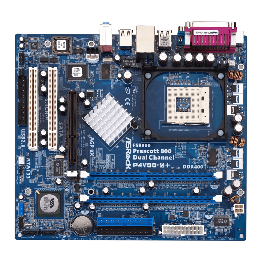
- Page 2 Chassis Speaker Header (SPEAKER 1) CPU Socket Chassis Fan Connector (CHA_FAN1) North Bridge Controller USB 2.0 Header (USB67, Blue) 2 x 184-pin DDR DIMM Slots Infrared Module Header (IR1) (Dual Channel A: DDR1, DDR3; Blue) Game Connector (GAME1) ATX 12V Connector (ATX12V1)
-
Page 3: Asrock I/O Plus
ASRock I/O Plus ASRock I/O Plus ASRock I/O Plus ASRock I/O Plus ASRock I/O Plus Parallel Port USB 2.0 Ports (USB0, USB1) RJ-45 Port USB 2.0 Ports (USB2, USB3) Line In (Light Blue) Serial Port: COM1 Line Out (Lime) PS/2 Keyboard Port (Purple) -
Page 4: Package Contents
This Quick Installation Guide contains introduction of the motherboard and step-by- step installation guide. More detailed information of the motherboard can be found in the user manual presented in the Support CD. Because the motherboard specifications and the BIOS software might be updated, the content of this manual will be subject to change without notice. -
Page 5: Specifications
1.2 Specifications 1.2 Specifications 1.2 Specifications 1.2 Specifications 1.2 Specifications Platform: ATX Form Factor: 12.0-in x 8.6-in, 30.5 cm x 21.8 cm CPU: Socket 478, supports Intel ® Pentium ® 4 (Prescott, Northwood, Willimate) / Celeron ® processor Chipsets: North Bridge: VIA PT880, FSB @ 800/533/400 MHz, ®... - Page 6 To improve heat dissipation, remember to spray thermal grease between the CPU and the heatsink when you install the PC system. Do NOT use a 3.3V AGP card on the AGP slot of this motherboard! It may cause permanent damage! Power Management for USB 2.0 works fine under Microsoft...
-
Page 7: Pre-Installation Precautions
The CPU fits only in one correct orientation. DO NOT force the CPU into the socket to avoid bending of the pins. STEP 4: When the CPU is in place, press it firmly on the socket while you push down the socket lever to secure the CPU. The lever clicks on the side tab to indicate that it is locked. -
Page 8: Installation Of Memory Modules (Dimm)
(the same brand, speed, size and chip-type) DDR DIMM pair in the slots of the same color. In other words, you have to install identical DDR DIMM pair in Dual Channel A (DDR1 and DDR3; Blue slots; see p.2 No. -
Page 9: Installing A Dimm
Unlock a DIMM slot by pressing the retaining clips outward. STEP 2: Align a DIMM on the slot such that the notch on the DIMM matches the break on the slot. The DIMM only fits in one correct orientation. It will cause permanent damage to the motherboard and the DIMM if you force the DIMM into the slot at incorrect orientation. -
Page 10: Expansion Slots (Pci And Agp Slots)
PCI slots: PCI slots are used to install expansion cards that have the 32-bit PCI interface. AGP slot: The AGP slot is used to install a graphics card. The ASRock AGP slot has a special design of clasp that can securely fasten the inserted graphics card. -
Page 11: Jumpers Setup
Note: To select +5VSB, it requires 2 Amp and higher standby current provided by power supply. (see p.2 No. 26) (see p.2 No. 25) Note: If the JL1 and JR1 jumpers are short, both the front panel and the rear panel audio connectors can work. Clear CMOS (CLRCMOS1, 2-pin jumper) 2-pin jumper (see p.2 No. -
Page 12: Onboard Headers And Connectors
FDD Connector (33-pin FLOPPY1) (see p.2 No. 16) the red-striped side to Pin1 Note: Make sure the red-striped side of the cable is plugged into Pin1 side of the connector. Primary IDE Connector (Blue) Secondary IDE Connector (Black) (39-pin IDE1, see p.2 No. 9) (39-pin IDE2, see p.2 No. - Page 13 ASRock I/O Plus provides you 6 ready-to-use USB 2.0 ports on (9-pin USB67) the rear panel. If the rear USB (see p.2 No. 20) ports are not sufficient, this USB 2.0 header is available to support 2 extra USB 2.0 ports.
- Page 14 Please note that it is necessary to connect a power supply with (4-pin ATX12V1) ATX 12V plug to this connector (see p.2 No. 7) so that it can provides sufficient power. Failing to do so will cause the failure to power up. ASRock P4V88/P4V88+ Motherboard...
- Page 15 STEP 3: Connect one end of the SATA data cable to the motherboard’s SATA connector. STEP 4: Connect the other end of the SATA data cable to the SATA hard disk. 2.7 Hot Plug and Hot Swap F Hot Plug and Hot Swap F...
-
Page 16: Installing Windows 2000 / Windows Xp With Raid Functions
SATA Hard Disks Installation and RAID Configuration”, which is located in the folder at the following path: .. \ SATA RAID BIOS and the document in the support CD, “Guide to VIA RAID Tool”, which is located in the folder at the following path: .. \ VIA RAID Tool 1. - Page 17 Functions Functions If you want to install Windows 98 / ME / 2000 / XP on your SATA HDDs without RAID functions or you want to install Windows 98 / ME / 2000 / XP on your IDE HDDs instead of SATA HDDs, please refer to the below methods for proper installation according to the different Windows OS versions.
-
Page 18: Bios Information
ME / 2000 / XP. The Support CD that came with the motherboard contains necessary drivers and useful utilities that will enhance motherboard features. To begin using the Support CD, insert the CD into your CD-ROM drive. It will display the Main Menu automatically if “AUTORUN” is enabled in your computer. If the Main Menu does not appear automatically, locate and double-click on the file “ASSETUP.EXE”... - Page 19 ASRock P4V88/P4V88+ Motherboard...
- Page 20 ® ® ® ASRock P4V88/P4V88+ Motherboard...
- Page 21 ® ® ASRock P4V88/P4V88+ Motherboard...
- Page 22 ASRock P4V88/P4V88+ Motherboard...
- Page 23 DDR1 DDR2 DDR3 DDR4 ASRock P4V88/P4V88+ Motherboard...
- Page 24 ASRock P4V88/P4V88+ Motherboard...
- Page 25 ASRock P4V88/P4V88+ Motherboard...
- Page 26 “ ” SATA2 SATA1 ASRock P4V88/P4V88+ Motherboard...
- Page 27 AUX1 ASRock P4V88/P4V88+ Motherboard...
- Page 28 ASRock P4V88/P4V88+ Motherboard...
- Page 29 ASRock P4V88/P4V88+ Motherboard...
- Page 30 ASRock P4V88/P4V88+ Motherboard...
- Page 31 ASRock P4V88/P4V88+ Motherboard...
- Page 32 ® ® ASRock P4V88/P4V88+ Motherboard...
- Page 33 Wir danken Ihnen für den Kauf des ASRock P4V88/P4V88+ Motherboard, ein zuverlässiges Produkt, welches unter den ständigen, strengen Qualitätskontrollen von ASRock gefertigt wurde. Es bietet Ihnen exzellente Leistung und robustes Design, gemäß der Verpflichtung von ASRock zu Qualität und Halbarkeit.
-
Page 34: Spezifikationen
1.2 Spezifikationen Plattform: ATX-Formfaktor: 30.5 cm x 21.8 cm; 12.0 Zoll x 8.6 Zoll CPU: Socket 478 für Intel ® Pentium ® 4 (Prescott, Northwood, Willimate) / Celeron ® Prozessoren Chipsatz: North Bridge: VIA PT880, FSB @ 800/533/400 MHz, unterstützt Hyper-Threading Technology... - Page 35 Shutdown durch. Bevor Sie das System neu starten, prüfen Sie bitte, ob der CPU-Lüfter am Motherboard richtig funktioniert, und stecken Sie bitte den Stromkabelstecker aus und dann wieder ein. Um die Wärmeableitung zu verbessern, bitte nicht vergessen, etwas Wärmeleitpaste zwischen CPU und Kühlkörper zu sprühen.
- Page 36 Unterlage, oder zurück in die Tüte, mit der die Komponente geliefert wurde. 2.1 CPU Installation Schritt 1: Öffnen Sie den CPU-Sockel, indem sie den Hebel leicht zur Seite und dann nach oben ziehen, auf einen Winkel von 90°. Schritt 2: Halten Sie die CPU korrekt ausgerichtet über den Sockel, so dass die markierte Ecke der CPU zum Hebelgelenk zeigt.
- Page 37 Steckplätzen gleicher Farbe installieren. Mit anderen Worten, sie müssen ein identisches DDR DIMM-Paar im Dual-Kanal A (DDR1 und DDR3; blaue Steckplätze, siehe Seite 2 Nr. 6) oder ein identisches DDR DIMM-Paar im Dual-Kanal B (DDR2 und DDR4; schwarze Steckplätze, siehe Seite 2 Nr. 10) installieren, damit die Dual- Kanal-Speichertechnologie aktiviert werden kann.
- Page 38 Öffnen Sie einen DIMM-Slot, indem Sie die seitlichen Clips nach außen drücken. Schritt 2: Richten Sie das DIMM-Modul so über dem Slot aus, dass das Modul mit der Kerbe in den Slot passt. Die DIMM-Module passen nur richtig herum eingelegt in die Steckplätze.
- Page 39 Gehäuseschacht (Slot) , den Sie nutzen möchten und behalten die Schraube für den Einbau der Karte. Schritt 3: Richten Sie die Karte über dem Slot aus und drücken Sie sie ohne Gewalt hinein, bis sie den Steckplatz korrekt ausfüllt. Schritt 4: Befestigen Sie die Karte mit der Schraube aus Schritt 2.
-
Page 40: Einstellung Der Jumper
(siehe S.2 - Nr. 1) und die PS/2 oder USB- Weckfunktionen zu aktivieren. Hinweis: Um +5VSB nutzen zu können, muss das Netzteil auf dieser Leitung 2A oder mehr leisten können. (siehe S.2 - Nr. 26) (siehe S.2 - Nr. 25) Hinweis: Sind die Jumper JL1 und JR1 gesetzt funktionieren beide Audioanschlüsse, Front- und Rückseite. - Page 41 Floppy-Laufwerk (33-Pin FLOPPY1) die rotgestreifte Seite auf Stift 1 (siehe S.2 - Nr. 16) Hinweis: Achten Sie darauf, dass die rotgestreifte Seite des Kabel mit der Stift 1- Seite des Anschlusses verbunden wird. Primärer IDE-Anschluss (blau) Sekundärer IDE-Anschluss (schwarz) (39-pin IDE1, siehe S.2 - Nr. 9) (39-pin IDE2, siehe S.2 - Nr.
- Page 42 Serial ATA- (SATA-) Sie können beide Enden des Datenkabel SATA-Datenkabels entweder mit der SATA-Festplatte oder dem SATA-Anschluss am Mainboard verbinden. Serial ATA- (SATA-) Verbinden Sie das schwarze Stromversorgungskabel Ende des SATA-Netzkabels mit dem Netzanschluss am Laufwerk. (Option) Verbindung zum Verbinden Sie dann das weiße...
- Page 43 Interne Audio-Anschlüsse Diese ermöglichen Ihnen Stereo-Signalquellen, wie z. B. (4-Pin CD1, 4-Pin AUX1) CD-ROM, DVD-ROM, TV-Tuner (CD1: siehe S.2 - No. 29) oder MPEG-Karten mit Ihrem AUX1 (AUX1: siehe S.2 - No. 28) System zu verbinden. Anschluss für Audio auf Dieses Interface zu einem der Gehäusevorderseite...
- Page 44 Verbinden Sie die ATX- Stromversorgung mit diesem (20-pin ATXPWR1) Header. (siehe S.2 - No. 31) Anschluss für Beachten Sie bitte, dass Sie eine 12V-ATX-Netzteil Stromversorgung mit ATX 12- Volt-Stecker mit diesem (4-pin ATX12V1) Anschluss verbinden müssen, (siehe S.2 - No. 7) damit ausreichend Strom geliefert werden kann.
- Page 45 Hot-Plug- und Hot-Swap-F Hot-Plug- und Hot-Swap-F Hot-Plug- und Hot-Swap-Funktion für SA unktion für SA unktion für SA unktion für SAT T T T T A A A A A -F -F -F -F -Festplatten estplatten estplatten estplatten Hot-Plug- und Hot-Swap-F Hot-Plug- und Hot-Swap-F unktion für SA...
- Page 46 Verwaltung der RAID-Funktionalität verwenden. Bitte lesen Sie dazu das Dokument „Anleitung zur SATA-Festplatteninstallation und RAID-Konfiguration“, das sich in folgendem Ordner auf der Support-CD befindet: .. \ SATA RAID BIOS Lesen Sie bitte auch das Dokument „Anleitung zum VIA RAID Tool“, das sich in diesem Ordner der Support-CD befindet: ..
- Page 47 Wenn Sie Windows 98 / ME / 2000 / XP ohne RAID-Funktionalität auf Ihren SATA- Festplatten installieren oder Windows 98 / ME / 2000 / XP statt auf SATA-Festplatten auf IDE-Festplatten installieren möchten, halten Sie sich bitte an die nachstehend aufgeführten Vorgehensweisen für die unterschiedlichen Windows-Betriebssystemversionen.
- Page 48 CD information Dieses Motherboard unterstützt eine Reiche von Microsoft Windows Betriebssystemen: 98 SE / ME / 2000 / XP. Die Ihrem Motherboard beigefügte Support-CD enthält hilfreiche Software, Treiber und Hilfsprogramme, mit denen Sie die Funktionen Ihres Motherboards verbessern können Legen Sie die Support-CD zunächst in Ihr CD-ROM-Laufwerk ein.
-
Page 49: Contenu Du Paquet
être trouvées dans le manuel l’utilisateur qui se trouve sur le CD d’assistance. Les spécifications de la carte mère et le BIOS ayant pu être mis à jour, le contenu de ce manuel est sujet à des changements sans notification. -
Page 50: Spécifications
Vitesse: 802.3u (Ethernet 10/100), support du Wake-On-LAN Surveillance Système: Mesure de la température CPU, Mesure de la température du châssis, Coupure auto du CPU en cas de surchauffe pour protéger le CPU (ASRock U-COP)(voir ATTENTION 3), Tachymètre de ventilateur CPU, Tachymètre de ventilateur de châssis,... - Page 51 Cette carte mère supporte la Technologie de Mémoire à Canal Double. Avant d’intégrer la Technologie de Mémoire à Canal Double, assurez- vous de bien lire le guide d’installation des modules mémoire en page 53 pour réaliser une installation correcte. Lorsqu’une surchauffe du CPU est détectée, le système s’arrête automatiquement.
- Page 52 Etape 1. Déverrouillez le support en relevant le levier selon un angle de 90 Etape 2. Mettez en place le CPU au dessus du support de telle façon que l’angle portant une marque corresponde à la base du levier du support.
- Page 53 DIMM DDR identiques (de la même marque, de la même vitesse, de la même taille et du même type de puce) dans les slots de même couleur. En d’autres termes, vous devez installer une paire de DIMM DDR identiques dans le Canal Double A (DDR1 et DDR3;...
- Page 54 Installation d’un module DIMM Installation d’un module DIMM Installation d’un module DIMM Ayez bien le soin de débrancher l’alimentation avant d’ajouter ou de retirer des modules DIMM ou les composants du système. Etape 1. Déverrouillez un connecteur DIMM en poussant les taquets de maintien vers l’extérieur.
-
Page 55: Installation D'une Carte D'extension
2.3 Slot d’extension (Slots PCI et Slot AGP) 2.3 Slot d’extension (Slots PCI et Slot AGP) Il y a 5 slots PCI et 1 slot AGP sur les cartes mères P4V88/P4V88+. Slots PCI: Les slots PCI sont utilisés pour installer des cartes d’extension dotées d’une interface PCI 32 bits. - Page 56 Note: Pour sélectionner +5VSB, il faut obligatoirement 2 Amp et un courant standby supérieur fourni par l’alimentation. (voir p.2 No. 26) (voir p.2 No. 25) Note: Si les cavaliers JL1 et JR1 sont reliés, les connecteurs audio du panneau avant et du panneau arrière peuvent fonctionner. Effacer la CMOS (CLRCMOS1, le cavalier le cavalier à...
- Page 57 (FLOPPY1 br. 33) le côté avec fil rouge côté Broche1 (voir p.2 No. 16) Note: Assurez-vous que le côté avec fil rouge du câble est bien branché sur le côté Broche1 du connecteur. Connecteur IDE primaire (bleu) Connecteur IDE secondaire (noir) (39-pin IDE1, voir p.2 No.
- Page 58 électrique. En-tête USB 2.0 ASRock I/O Plus vous apporte 6 ports USB 2.0 par défaut sur (USB67 br.9) le panneau arrière. Si le nombre (voir p.2 No. 20) des ports USB à l’arrière n’est pas suffisant, cette En-tête USB 2.0 (USB67) permet de...
- Page 59 à partir de sources (CD1 br. 4, AUX1 br. 4) stéréo comme un CD-ROM, DVD- (CD1: voir p.2 No. 29) AUX1 ROM, un tuner TV ou une carte (AUX1: voir p.2 No. 28) MPEG. Connecteur audio panneau C’est une interface pour un câble avant audio en façade qui permet le...
- Page 60 Cette section vous guidera pour l’installation des disques durs SATA. ETAPE 1 : Installez les disques durs SATA dans les baies pour disques de votre châssis. ETAPE 2 : Connectez le câble d’alimentation SATA au disque dur SATA.
- Page 61 Qu’est-ce que la fonction « Hot Swap » ? Si les disques durs sont montés en configuration RAID1 l’action d’insérer et de retirer des disques SATA alors que le système est sous tension et en fonctionnement s’appelle le “Hot Swap” .
- Page 62 CD d’assistance, “Guide d’installation des disques durs SATA et de configuration RAID, ” qui se trouve dans le dossier sur le chemin suivant : .. \ SATA RAID BIOS et le document sur le CD d’assistance, “Guide de l’Utilitaire VIA RAID pour Windows,”...
- Page 63 RAID fonctions RAID Si vous voulez installer Windows 98 / ME / 2000 / XP sur vos disques durs SATA sans les fonctions RAID ou si vous voulez installer Windows 98 / ME / 2000 / XP bits sur vos disques durs IDE au lieu de disques durs SATA, veuillez vous reporter aux méthodes ci-dessous pour l’installation correcte en fonction des...
- Page 64 Cette carte mère supporte divers systèmes d’exploitation Microsoft Windows: 98 SE / ME / 2000 / XP. Le CD technique livré avec cette carte mère contient les pilotes et les utilitaires nécessaires pour améliorer les fonctions de la carte mère.
-
Page 65: Contenuto Della Confezione
Grazie per aver scelto una scheda madre ASRock P4V88/P4V88+, una scheda madre affidabile prodotta secondo i severi criteri di qualità ASRock. Le prestazioni eccellenti e il design robusto si conformano all’impegno di ASRock nella ricerca della qualità e della resistenza. - Page 66 Voltaggio: +12V, +5V, +3V, Vcore Slot PCI: 5 slot con PCI Spec 2.2 Slot AGP: 1 slot AGP, supporta scheda AGP a 1.5V, modelli 8X / 4X (vedi ATTENZIONE 4) USB 2.0: 8 porte USB 2.0 : comprende 6 porte USB 2.0 pronte all’uso nel pannello posteriore, oltre ad una sulla scheda che supporta altre 2 porte USB 2.0 aggiuntive (vedi ATTENZIONE 5)
- Page 67 NON usare schede AGP da 3,3 V nello slot AGP di questa motherboard! Ciò potrebbe provocare danni permanenti! La Gestione Risorse per USB 2.0 funziona perfettamente con Microsoft ®...
-
Page 68: Installazione
Leggere le seguenti precauzioni prima di installare componenti delle schede madri o di cambiare le impostazioni delle schede madri. 1. Togliere il cavo dalla presa elettrica prima di toccare le componenti. In caso contrario la schedamadre, le periferiche, e/o i componenti possono subire gravi danni. - Page 69 In altre parole, è necessario installare coppie identiche di DIMM DDR nel canale doppio A (DDR1 e DDR3; alloggiamenti blu; vedere pag. 2 Nr. 6) oppure coppie identiche di DIMM DDR nel canale doppio B (DDR2 e DDR4;...
- Page 70 Sbloccare lo slot DIMM premendo i fermi che lo trattengono verso l’esterno. Step 2. Allineare una DIMM sullo slot così che il pettine della DIMM combaci con la sua sede sullo slot. La DIMM può essere montata correttamente soltanto con un orientamento.
- Page 71 2.3 Slot di espansione (PCI e slot AGP) 2.3 Slot di espansione (PCI e slot AGP) Esistono 5 slot PCI e 1 slot AGI su entrambe le schede madri P4V88/P4V88+. Slot PCI: Sono utilizzati per installare schede di espansione con Interfaccia PCI a 32-bit.
- Page 72 Nota: Per selezionare +5VSB, si richiedono almeno 2 Ampere e il consumo di corrente in standby sarà maggiore. (vedi p.2 Nr. 26) (vedi p.2 Nr. 25) Nota: Se i jumper JL1 e JR1 sono chiusi, funzionano sia i connettori audio frontali che posteriori. Resettare la CMOS (CLRCMOS1, jumper a 2 pin) jumper a 2 pin (vedi p.2 Nr.
- Page 73 Floppy disk (33-pin FLOPPY1) Lato del Pin1 con la striscia rossa (vedi p.2 Nr. 16) Nota: Assicurarsi che il lato del cavo con la striscia rossa sia inserito nel lato Pin1 del connettore. Connettore IDE primario (blu) Connettore IDE secondario (nero) (39-pin IDE1, vedi p.2 Nr.
- Page 74 USB 2.0 aggiuntive. Collettore USB 2.0 Questo collettore USB4_5 è condiviso condiviso con le porte USB 2.0 4 e 5 su ASRock I/O Plus™. (9-pin USB4_5) Quando si utilizzano le porte (vedi p.2 Nr. 30) USB del pannello frontale,...
- Page 75 Connettori audio interni Permettono di ricevere input stereo audio da fonti di suono (4-pin CD1, 4-pin AUX1) come CD-ROM, DVD-ROM,TV (CD1: vedi p.2 Nr. 29) tuner, o schede MPEG. (AUx1: vedi p.2 Nr. 28) AUX1 Connettore audio sul pannello È un’interfaccia per il cavo del frontale pannello audio.
- Page 76 (vedi p.2 Nr. 31) Connettore ATX 12V È necessario collegare una alimentazione con spinotto da (4-pin ATX12V1) 12V ATX a questo connettore (vedi p.2 Nr. 7) in modo che possa fornire energia sufficiente. In caso contrario l’unità non si avvia.
- Page 77 Questa sezione illustra come installare hard disk SATA. 1° PASSO: Installare gli Hard Disk SATA negli spazi per le unità disco del telaio. 2° PASSO: Collegare il cavo d’alimentazione SATA al disco rigido SATA.
- Page 78 Iniziare a formattare e copiare i file [Y/N]?) Inserire un dischetto floppy nel floppy drive e premere <Y>. E. Il sistema inizierà a formattare il floppy-disk e a copiare i driver SATA su questo. Passo 2: Usare “SATA RAID BIOS” per impostare la configurazione RAID.
- Page 79 RAID funzioni RAID Se si desidera installare Windows 98 / ME / 2000 / XP sulle unità disco rigido SATA senza funzioni RAID o installare Windows 98 / ME / 2000 / XP sulle unità disco rigido IDE e non sulle unità di SATA, far riferimento ai metodi illustrati di seguito, per eseguire l’operazione nella maniera corretta in base alla diversa versione di...
- Page 80 Windows : 98 SE / ME / 2000 / XP. Il CD di supporto a corredo della scheda madre contiene i driver e utilità necessari a potenziare le caratteristiche della scheda. Inserire il CD di supporto nel lettore CD-ROM. Se la funzione “AUTORUN” è attivata nel computer, apparirà...
-
Page 81: Contenido De La Caja
ASRock. Esta Guía rápida de instalación contiene una introducción a la placa base y una guía de instalación paso a paso. Puede encontrar una información más detallada sobre la placa base en el manual de usuario incluido en el CD de soporte. - Page 82 (ver ATENCIÓN 4) USB 2.0: 8 puertos USB 2.0: incluyen 6 puertos USB 2.0 listos para su uso en el panel anterior, más un cabezal en la placa con soporte para 2 puertos USB 2.0 adicionales (ver ATENCIÓN 5) ASRock P4V88/P4V88+ Motherboard...
- Page 83 Para mejorar la disipación de calor, acuérdese de aplicar thermal grease entre el procesador y el disipador de calor cuando usted instala el sistema de PC. NO utilice una tarjeta AGP de 3,3V AGP en la ranura AGP de esta placa base. Podría causar daños permanentes. ® ®...
-
Page 84: Instalación
Paso 1. Desbloquee el zócalo arrastrando la palanca hacia afuera y hacia arriba en un ángulo de 90 Paso 2. Coloque el CPU sobre el zócalo tal como la esquina marcada de CPU corresponde la esquina de zócalo cerca del terminal de la palanca, mientras tanto asegúrese que el CPU está... -
Page 85: Instalación De Memoria
DDR DIMM de Doble Canal A (DDR1 y DDR3; Ranuras Azules; consulte la p. 2 N. 6) o pares idénticos DDR DIMM en el Doble Canal B (DDR2 y DDR4; ranuras Negras; consulte p.2 N.10), de modo que pueda activarse la Tecnología de Memoria de Doble Canal. - Page 86 Asegúrese de desconectar la fuente de alimentación antes de añadir o retirar módulos DIMM o componentes del sistema. Paso 1. Empuje los clips blancos de retención por el extremo de cada lado de la ranura de memoria. Paso 2. Encaje la muesca del DIMM hacia la cumbrera de la ranura.
- Page 87 Paso 2. Quite la tapa que corresponde a la slot que desea utilizar. Paso 3. Encaje el conector de la tarjeta a la slot. Empuje firmemente la tarjeta en la slot. Paso 4. Asegure la tarjeta con tornillos.
- Page 88 (ver p.2, N. 26) (ver p.2, N. 25) Atención: Si los puentes JL1 y JR1 son cortos, tanto el conector de audio del panel frontal como del panel posterior pueden funcionar. Limpiar CMOS (CLRCMOS1, jumper de 2 pins) jumper de 2 pins (ver p.2, N.
- Page 89 (ver p.2 N. 16) la banda roja debe quedar en el mismo lado que el contacto 1 Atención: Asegúrese que la banda roja del cable queda situado en el mismo lado que el contacto 1 de la conexión. IDE conector primario (azul) IDE conector secundario (negra) (39-pin IDE1, ver p.2 N.
- Page 90 USB del panel (ver p.2, N. 30) frontal conectando el cable USB del panel frontal a este cabezal (USB4_5), los puertos USB 4 y 5 en el ASRock I/O Plus no funcionarán. Conector de módulo Infrared Soporta módulo Infrared de transmisión y recepción...
- Page 91 (ver p.2, N. 19) Conector del ventilador Conecte el cable del ventilador de la CPU de la CPU a este conector y haga coincidir el cable negro (3-pin CPU_FAN1) con el conector de tierra. (ver p.2, N. 2) Conexión de juegos...
- Page 92 Conector de ATX 12V power Tenga en cuenta que es necesario conectar este (4-pin ATX12V1) conector a una toma de corriente (ver p.2, N. 7) con el enchufe ATX 12V, de modo que proporcione suficiente electricidad. De lo contrario no se podrá...
- Page 93 PASO 2: Conecte el cable de alimentación SATA al disco duro SATA. PASO 3: Conecte un extremo del cable de datos SATA al conector SATA de la placa base. PASO 4: Conecte el otro extremo del cable de datos SATA al disco duro SATA.
- Page 94 .. \ SATA RAID BIOS y el documento contenido en el CD de soporte, “Guía de VIA RAID Tool”, situado en la carpeta que indica la ruta de acceso siguiente: .. \ VIA RAID Tool 1. Windows 98 / Windows ME no admiten funciones RAID.
- Page 95 RAID funciones RAID Si desea instalar Windows 98 / ME / 2000 / XP en sus discos duros SATA sin funciones RAID o si desea instalar Windows 98 / ME / 2000 / XP en sus discos duros IDE, consulte los métodos siguientes para una instalación adecuada, según las distintas versiones de sistemas operativos Windows.
- Page 96 Esta placa-base soporta diversos tipos de sistema operativo Windows : 98SE / ME / 2000 / XP El CD de instalación que acompaña la placa-base trae todos los drivers y programas utilitarios para instalar y configurar la placa-base. Para iniciar la instalación, ponga el CD en el lector de CD y se desplegará el Menú...