ASROCK N68C-GS Installation Manual
Hide thumbs
Also See for N68C-GS:
- Installation manual (26 pages) ,
- User manual (57 pages) ,
- Brochure (6 pages)
Advertisement
Copyright Notice:
Copyright Notice:
Copyright Notice:
Copyright Notice:
Copyright Notice:
No part of this installation guide may be reproduced, transcribed, transmitted, or trans-
lated in any language, in any form or by any means, except duplication of documen-
tation by the purchaser for backup purpose, without written consent of ASRock Inc.
Products and corporate names appearing in this guide may or may not be registered
trademarks or copyrights of their respective companies, and are used only for identifica-
tion or explanation and to the owners' benefit, without intent to infringe.
Disclaimer:
Disclaimer:
Disclaimer:
Disclaimer:
Disclaimer:
Specifications and information contained in this guide are furnished for informational
use only and subject to change without notice, and should not be constructed as a
commitment by ASRock. ASRock assumes no responsibility for any errors or omissions
that may appear in this guide.
With respect to the contents of this guide, ASRock does not provide warranty of any kind,
either expressed or implied, including but not limited to the implied warranties or
conditions of merchantability or fitness for a particular purpose. In no event shall
ASRock, its directors, officers, employees, or agents be liable for any indirect, special,
incidental, or consequential damages (including damages for loss of profits, loss of
business, loss of data, interruption of business and the like), even if ASRock has been
advised of the possibility of such damages arising from any defect or error in the guide
or product.
This device complies with Part 15 of the FCC Rules. Operation is subject to the
following two conditions:
(1) this device may not cause harmful interference, and
(2) this device must accept any interference received, including interference that
may cause undesired operation.
CALIFORNIA, USA ONLY
The Lithium battery adopted on this motherboard contains Perchlorate, a toxic
substance controlled in Perchlorate Best Management Practices (BMP) regulations
passed by the California Legislature. When you discard the Lithium battery in
California, USA, please follow the related regulations in advance.
"Perchlorate Material-special handling may apply, see
www.dtsc.ca.gov/hazardouswaste/perchlorate"
ASRock Website: http://www.asrock.com
Copyright©2010 ASRock INC. All rights reserved.
ASRock
N68C-GS UCC / N68C-S UCC
Published March 2010
Motherboard
1 1 1 1 1
Advertisement

Related Manuals for ASROCK N68C-GS


Summary of Contents for ASROCK N68C-GS
- Page 1 ASRock. ASRock assumes no responsibility for any errors or omissions that may appear in this guide. With respect to the contents of this guide, ASRock does not provide warranty of any kind, either expressed or implied, including but not limited to the implied warranties or conditions of merchantability or fitness for a particular purpose.
-
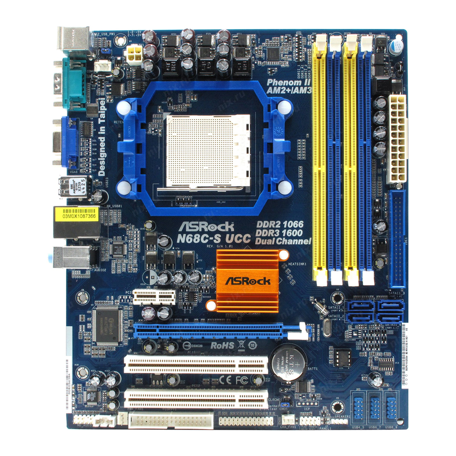
Page 2: Motherboard Layout
Motherboard Layout Motherboard Layout Motherboard Layout Motherboard Layout Motherboard Layout (N68C (N68C (N68C- - - - - GS UCC / N68C GS UCC / N68C GS UCC / N68C GS UCC / N68C-S UCC) -S UCC) -S UCC) -S UCC) - Page 3 VGA Port Front Speaker (Lime) COM Port Microphone (Pink) PS/2 Keyboard Port (Purple) * There are two LED next to the LAN port. Please refer to the table below for the LAN port LED indications. LAN Port LED Indications ACT/LINK SPEED...
- Page 4 VGA Port Front Speaker (Lime) COM Port Microphone (Pink) PS/2 Keyboard Port (Purple) * There are two LED next to the LAN port. Please refer to the table below for the LAN port LED indications. LAN Port LED Indications ACT/LINK SPEED...
- Page 5 It delivers excellent performance with robust design conforming to ASRock’s com- mitment to quality and endurance. In this manual, chapter 1 and 2 contain introduction of the motherboard and step-by-step guide to the hardware installation. Chapter 3 and 4 contain the configuration guide to BIOS setup and information of the Support CD.
-
Page 6: Specifications
- Micro ATX Form Factor: 9.6-in x 8.2-in, 24.4 cm x 20.8 cm - Support for Socket AM2+ / AM2 processors: AMD Phenom FX / Phenom / Athlon 64 FX / Athlon 64 X2 Dual-Core / Athlon X2 Dual-Core / Athlon 64 / Sempron processor... - Page 7 - 1 x Serial Port: COM1 - 1 x VGA Port - 4 x Ready-to-Use USB 2.0 Ports - 1 x RJ-45 LAN Port with LED (ACT/LINK LED and SPEED LED) - HD Audio Jack: Line in / Front Speaker / Microphone Connector - 4 x Serial ATAII 3.0Gb/s connectors, support RAID (RAID 0,...
- Page 8 Overclocking may affect your system stability, or even cause damage to the components and devices of your system. It should be done at your own risk and expense. We are not responsible for possible damage caused by overclocking.
- Page 9 USB flash drive or hard drive must use FAT32/16/12 file system. 14. The software name itself – OC DNA literally tells you what it is capable of. OC DNA, an exclusive utility developed by ASRock, provides a conve- nient way for the user to record the OC settings and share with others.
- Page 10 17. This motherboard supports ASRock AM2 Boost overclocking technology. If you enable this function in the BIOS setup, the memory performance will improve up to 12.5%, but the effect still depends on the AM2 CPU you adopt. Enabling this function will overclock the chipset/CPU reference clock. However, we can not guarantee the system stability for all CPU/DRAM configurations.
- Page 11 Installation Installation Installation This is a Micro ATX form factor (9.6-in x 8.2-in, 24.4 cm x 20.8 cm) motherboard. Before you install the motherboard, study the configuration of your chassis to en- sure that the motherboard fits into it. Pre-installation Precautions...
-
Page 12: Installation Of Cpu Fan And Heatsink
Step 4. When the CPU is in place, press it firmly on the socket while you push down the socket lever to secure the CPU. The lever clicks on the side tab to indicate that it is locked. - Page 13 Channel Memory Technology. For dual channel configuration, you always need to install identical (the same brand, speed, size and chip-type) DDR2/DDR3 DIMM pair in the slots of the same color. In other words, you have to install identical DDR2 DIMM pair in Dual Channel (DDRII_1 and DDRII_2; Yellow slots;...
- Page 14 Unlock a DIMM slot by pressing the retaining clips outward. Step 2. Align a DIMM on the slot such that the notch on the DIMM matches the break on the slot. The DIMM only fits in one correct orientation. It will cause permanent damage to the motherboard and the DIMM if you force the DIMM into the slot at incorrect orientation.
- Page 15 PCI slots: PCI slots are used to install expansion cards that have the 32-bit PCI interface. PCIE slots: PCIE1 (PCIE x1 slot) is used for PCI Express cards with x1 lane width cards, such as Gigabit LAN card, SATA2 card, etc.
-
Page 16: Easy Multi Monitor Feature
PCI Express VGA card to PCIE2 (PCIE x16 slot). Please refer to page 15 for proper expansion card installation procedures for details. 2. Connect the D-Sub monitor cable to the VGA/D-Sub port on the I/O panel of this motherboard. Connect another D-Sub monitor cable to the VGA/D-Sub connector of the add-on PCI Express VGA card. -
Page 17: Jumpers Setup
CLRCMOS1 for 5 seconds. However, please do not clear the CMOS right after you update the BIOS. If you need to clear the CMOS when you just finish updating the BIOS, you must boot up the system first, and then shut it down before you do the clear-CMOS action. - Page 18 Floppy Connector (33-pin FLOPPY1) (see p.2 No. 23) the red-striped side to Pin1 Note: Make sure the red-striped side of the cable is plugged into Pin1 side of the connector. Primary IDE connector (Blue) (39-pin IDE1, see p.2 No. 9)
- Page 19 HDA to function correctly. Please follow the instruction in our manual and chassis manual to install your system. 2. If you use AC’97 audio panel, please install it to the front panel audio header as below: A.
- Page 20 Though this motherboard provides 4-Pin CPU fan (Quiet Fan) support, the 3-Pin CPU fan still can work successfully even without the fan speed control function. If you plan to connect the 3-Pin CPU fan to the CPU fan connector on this motherboard, please connect it to Pin 1-3.
- Page 21 Though this motherboard provides 24-pin ATX power connector, it can still work if you adopt a traditional 20-pin ATX power supply. To use the 20-pin ATX power supply, please plug your power supply along with Pin 1 and Pin 13.
-
Page 22: Driver Installation Guide
Untied Overclocking function, please enter “Overclock Mode” option of BIOS setup to set the selection from [Auto] to [CPU, PCIE, Async.]. Therefore, CPU FSB is untied during overclocking, but PCI / PCIE buses are in the fixed mode so that FSB can operate under a more stable overclocking environment. - Page 23 ROM drive. It will display the Main Menu automatically if “AUTORUN” is enabled in your computer. If the Main Menu does not appear automatically, locate and double- click on the file “ASSETUP.EXE” from the “BIN” folder in the Support CD to display the menus.
- Page 24 1. Einführung 1. Einführung 1. Einführung Wir danken Ihnen für den Kauf des ASRock N68C-GS UCC / N68C-S UCC Motherboard, ein zuverlässiges Produkt, welches unter den ständigen, strengen Qualitätskontrollen von ASRock gefertigt wurde. Es bietet Ihnen exzellente Leistung und robustes Design, gemäß der Verpflichtung von ASRock zu Qualität und Halbarkeit.
- Page 25 Spezifikationen Spezifikationen Spezifikationen Plattform - Micro ATX-Formfaktor: 24.4 cm x 20.8 cm; 9.6 Zoll x 8.2 Zoll - Unterstützung für Socket AM2+ / AM2-Prozessoren: AMD Phenom FX / Phenom / Athlon 64 FX / Athlon 64 X2 Dualkern / Athlon X2 Dualkern / Athlon 64 / Sempron-Prozessor (siehe VORSICHT 1) - Unterstützung von AM3-Prozessoren: AMD Phenom...
- Page 26 - 1 x Serieller port: COM 1 - 1 x VGA port - 4 x Standard-USB 2.0-Anschlüsse - 1 x RJ-45 LAN Port mit LED (ACT/LINK LED und SPEED LED) - Audioanschlüsse: Line In / Line Out / Mikrofon Anschlüsse - 4 x SATAII-Anschlüsse, unterstützt bis 3.0 Gb/s...
- Page 27 Beachten Sie bitte, dass Overclocking, einschließlich der Einstellung im BIOS, Anwenden der Untied Overclocking-Technologie oder Verwenden von Overclocking-Werkzeugen von Dritten, mit einem gewissen Risiko behaftet ist. Overclocking kann sich nachteilig auf die Stabilität Ihres Systems auswirken oder sogar Komponenten und Geräte Ihres Systems beschädigen.
- Page 28 Durch Betriebssystem-Einschränkungen kann die tatsächliche Speichergröße weniger als 4 GB betragen, da unter Windows ® 7 / Vista™ / XP etwas Speicher zur Nutzung durch das System reserviert wird. Unter Windows ® OS mit 64-Bit-CPU besteht diese Einschränkung nicht. Ob die Speichergeschwindigkeit 1066 MHz unterstützt wird, hängt von der von Ihnen eingesetzten AM2+-CPU ab.
- Page 29 USB-Flash-Laufwerk oder die Festplatte das Dateisystem FAT32/16/12 benutzen muss. 14. Allein der Name – OC DNA* – beschreibt es wörtlich, was die Software zu leisten vermag. OC DNA ist ein von ASRock exklusiv entwickeltes Dienstprogramm, das Nutzern eine bequeme Möglichkeit bietet, Übertaktungseinstellungen aufzuzeichnen und sie Anderen mitzuteilen.
- Page 30 +5VSB (Standby) zu setzen (siehe S.2, No. 1) und die PS/2 oder USB- Weckfunktionen zu aktivieren. Hinweis: Um +5VSB nutzen zu können, muss das Netzteil auf dieser Leitung 2A oder mehr leisten können. CMOS löschen (CLRCMOS1, 3-Pin jumper) (siehe S.2, No. 21)
- Page 31 (33-Pin FLOPPY1) die rotgestreifte Seite auf Stift 1 (siehe S.2, No. 23) Hinweis: Achten Sie darauf, dass die rotgestreifte Seite des Kabel mit der Stift 1- Seite des Anschlusses verbunden wird. Primärer IDE-Anschluss (blau) (39-pin IDE1, siehe S.2, No. 9)
- Page 32 1. High Definition Audio unterstützt Jack Sensing (automatische Erkennung falsch angeschlossener Geräte), wobei jedoch die Bildschirmverdrahtung am Gehäuse HDA unterstützen muss, um richtig zu funktionieren. Beachten Sie bei der Installation im System die Anweisungen in unserem Handbuch und im Gehäusehandbuch. ASRock...
- Page 33 2. Wenn Sie die AC’97-Audioleiste verwenden, installieren Sie diese wie nachstehend beschrieben an der Front-Audioanschlussleiste: A. Schließen Sie Mic_IN (MIC) an MIC2_L an. B. Schließen Sie Audio_R (RIN) an OUT2_R und Audio_L (LIN) an OUT2_L an. C. Schließen Sie Ground (GND) an Ground (GND) an.
- Page 34 Obwohl dieses Motherboard einen 24-pol. ATX-Stromanschluss bietet, kann es auch mit einem modifizierten traditionellen 20-pol. ATX-Netzteil verwendet werden. Um ein 20-pol. ATX-Netzteil zu verwenden, stecken Sie den Stecker mit Pin 1 und Pin 13 ein. Installation eines 20-pol. ATX-Netzteils Anschluss für...
- Page 35 Erscheint der Wilkommensbildschirm nicht, so “doppelklicken” Sie bitte auf das File ASSETUP.EXE im BIN-Verzeichnis der Support-CD, um die Menüs aufzurufen. Das Setup-Programm soll es Ihnen so leicht wie möglich machen. Es ist menügesteuert, d.h. Sie können in den verschiedenen Untermenüs Ihre Auswahl treffen und die Programme werden dann automatisch installiert.
- Page 36 Contenu du paquet Carte mère ASRock N68C-GS UCC / N68C-S UCC (Facteur de forme Micro ATX: 9.6 pouces x 8.2 pouces, 24.4 cm x 20.8 cm) Guide d’installation rapide ASRock N68C-GS UCC / N68C-S UCC CD de soutien ASRock N68C-GS UCC / N68C-S UCC Deux câble de données Serial ATA (SATA) (Optionnelle)
- Page 37 (voir ATTENTION 1) - Prise en charge des processeurs sur AM3: Processeur Phenom II X4 / X3 / X2 / Athlon II X4 / X3 / X2 / Sempron d’AMD - Supporte UCC (Unlock CPU Core) (voir ATTENTION 2) - Supporte la technologie Cool ‘n’ Quiet™ d’AMD - FSB 1000 MHz (2.0 GT/s)
- Page 38 - br. 24 connecteur d’alimentation ATX - br. 4 connecteur d’alimentation 12V ATX - Connecteurs audio internes - Connecteur audio panneau avant - 3 x En-tête USB 2.0 (prendre en charge 6 ports USB 2.0 supplémentaires) (voir ATTENTION 10) BIOS - 8Mb BIOS AMI - BIOS AMI - Support du “Plug and Play”...
- Page 39 XP / XP 64-bit Certifications - FCC, CE, WHQL * Pour de plus amples informations sur les produits, s’il vous plaît visitez notre site web: http://www.asrock.com ATTENTION Il est important que vous réalisiez qu’il y a un certain risque à effectuer l’overclocking, y compris ajuster les réglages du BIOS, appliquer la technologie Untied Overclocking, ou...
- Page 40 Avant d’installer le disque dur SATAII au connecteur SATAII, veuillez lire le Guide « Installation du disque dur SATAII » à la page 25 du « Manuel de l’utilisateur » qui se trouve sur le CD de support pour régler votre lecteur de disque dur SATAII au mode SATAII.
- Page 41 (L’économiseur d’énergie intelligent). Site Web d’ASRock: http://www.asrock.com 13. O ASRock Instant Flash é um utilitário de flash do BIOS incorporado na memória Flash ROM. Esta prática ferramenta de actualização do BIOS permite-lhe actualizar o BIOS do sistema sem necessitar de entrar nos ®...
- Page 42 3 sur CLRCMOS1 pendant 5 secondes. Après avoir court-circuité le cavalier Effacer la CMOS, veuillez enlever le capuchon de cavalier. Toutefois, veuillez ne pas effacer la CMOS tout de suite après avoir mis le BIOS à jour. Si vous avez besoin d’effacer la CMOS lorsque vous avez fini de mettre le BIOS à...
- Page 43 (FLOPPY1 br. 33) le côté avec fil rouge côté Broche1 (voir p.2 fig. 23) Note: Assurez-vous que le côté avec fil rouge du câble est bien branché sur le côté Broche1 du connecteur. Connecteur IDE primaire (bleu) (IDE1 br. 39, voir p.2 No. 9)
- Page 44 MPEG. 1. L’audio à haute définition (HDA) prend en charge la détection de fiche, mais le fil de panneau sur le châssis doit prendre en charge le HDA pour fonctionner correctement. Veuillez suivre les instructions dans notre manuel et le manuel de châssis afin installer votre système.
- Page 45 (voir p.2 fig. 2) ien que cette carte mère offre un support de (Ventilateur silencieux) ventilateur de CPU à 4 broches , le ventilateur de CPU à 3 broches peut bien fonctionner même sans la fonction de commande de vitesse du ventilateur.
- Page 46 (voir p.2 fig. 8) Bien que cette carte mère fournisse un connecteur de courant ATX 24 broches, elle peut encore fonctionner si vous adopter une alimentation traditionnelle ATX 20 broches. Pour utiliser une alimentation ATX 20 broches, branchez à...
- Page 47 BIOS après le POST, veuillez redémarrer le système en pressant <Ctl> + <Alt> + <Suppr>, ou en pressant le bouton de reset sur le boîtier du système. Vous pouvez également redémarrer en éteignant le système et en le rallumant.
- Page 48 1. Introduzione Grazie per aver scelto una scheda madre ASRock N68C-GS UCC / N68C-S UCC, una scheda madre affidabile prodotta secondo i severi criteri di qualità ASRock. Le prestazioni eccellenti e il design robusto si conformano all’impegno di ASRock nella ricerca della qualità...
- Page 49 - Micro ATX Form Factor: 9.6-in x 8.2-in, 24.4 cm x 20.8 cm Processore - Supporto per processori Socket AM2+ / AM2: AMD Phenom FX / Phenom / Athlon 64 FX / Athlon 64 X2 Dual-Core / Athlon X2 Dual-Core / Athlon 64 / processore Sempron (vedi ATTENZIONE 1)
- Page 50 - 1 x Porta COM - 1 x Porta VGA - 4 x porte USB 2.0 già integrate - 1 x porte LAN RJ-45 con LED (LED azione/collegamento e LED velocità) - Audio Jack: Line In / Line Out / Microfono Connettori - 4 x connettori SATAII 3.0Go/s, sopporta RAID (RAID 0, RAID 1,...
- Page 51 * Per ulteriori informazioni, prego visitare il nostro sito internet: http://www.asrock.com AVVISO Si prega di prendere atto che la procedura di overclocking implica dei rischi, come anche la regolazione delle impostazioni del BIOS, l’applicazione della tecnologia Untied Overclocking Technology, oppure l’uso di strumenti di overclocking forniti da terzi. L’overclocking può...
- Page 52 64-bit / Vista / XP 64 bit / XP SP1; SP2. 11. Si tratta di uno strumento di sicronizzazione ASRock di face uso in grado di implementare il controllo del sistema tramite la funzione di hardware monitor e sincronizzare le Vostre unita‘ hardware per ottenere la migliore prestazione in Windows ®...
- Page 53 (dischi floppy) o altre complicate utilità Flash. Si prega di notare che l’unità Flash USB o il disco rigido devono usare il File System FAT32/16/ 14. Il nome stesso del software – OC DNA – dice di cosa è capace. OC DNA, una utilità esclusiva sviluppata da ASRock, fornisce un modo comodo per registrare le impostazioni OC e condividerle con gli altri.
- Page 54 Quando il ponticello è posizionato sui pin, il jumper è “CORTOCIRCUITATO”. Se sui pin non ci sono ponticelli, il jumper è “APERTO”. L’illustrazione mostra un jumper a 3 pin in cui il pin1 e il pin2 sono “CORTOCIRCUITATI” quando il ponticello è CORTOCIRCUITATO APERTO posizionato su questi pin.
- Page 55 (33-pin FLOPPY1) (vedi p.2 item 23) Lato del Pin1 con la striscia rossa Nota: Assicurarsi che il lato del cavo con la striscia rossa sia inserito nel lato Pin1 del connettore. Connettore IDE primario (blu) (39-pin IDE1, vedi p.2 Nr. 9)
- Page 56 1. La caratteristica HDA (High Definition Audio) supporta il rilevamento dei connettori, però il pannello dei cavi sul telaio deve supportare la funzione HDA (High Definition Audio) per far sì che questa operi in modo corretto. Attenersi alle istruzioni del nostro manuale e del manuale del telaio per installare il sistema.
- Page 57 Sebbene la presente scheda madre disponga di un supporto per ventola CPU a 4 piedini (ventola silenziosa), la ventola CPU a 3 piedini è in grado di funzionare anche senza la funzione di controllo della velocità della ventola. Se si intende collegare la ventola CPU a 3 piedini al connettore della ventola CPU su questa scheda madre, collegarla ai piedini 1-3.
- Page 58 ATX a 24 pin, ma può funzionare lo stesso se si adotta un alimentatore ATX a 20 pin. Per usare l’alimentatore ATX a 20 pin, collegare l’alimentatore con il Pin 1 e il Pin 13. Installazione dell’alimentatore ATX a 20 pin Connettore ATX 12V È...
- Page 59 BIOS; altrimenti, POST continua con i suoi test di routine. Per entrare il BIOS Setup dopo il POST, riavvia il sistema premendo <Ctl> + <Alt> + <Delete>, o premi il tasto di reset sullo chassis del sistema. El BIOS Setup Utility es diseñádo “user-friendly”.
- Page 60 ASRock. Esta Guía rápida de instalación contiene una introducción a la placa base y una guía de instalación paso a paso. Puede encontrar una información más detallada sobre la placa base en el manual de usuario incluido en el CD de soporte.
- Page 61 - Compatibilidad con procesadores con AM3: procesador AMD Phenom II X4 / X3 / X2 / Athlon II X4 / X3 / X2 / Sempron - Con soporte UCC (Unlock CPU Core) (vea ATENCIÓN 2) - Con soporte para tecnología Cool ‘n’ Quiet de AMD - FSB 1000 MHz (2.0 GT/s)
- Page 62 - 1 x puerto serial: COM1 - 1 x Puerto VGA - 4 x puertos USB 2.0 predeterminados - 1 x Puerto LAN RJ-45 con LED (LED de ACCIÓN/ENLACE y LED de VELOCIDAD) - Audio Jack: Line In / Line Out / Micrófono...
- Page 63 ADVERTENCIA Tenga en cuenta que hay un cierto riesgo implícito en las operaciones de aumento de la velocidad del reloj, incluido el ajuste del BIOS, aplicando la tecnología de aumento de velocidad liberada o utilizando las herramientas de aumento de velocidad de otros fabricantes.
- Page 64 Esta placa base soporta Tecnología de Memoria de Doble Canal. Antes de implementar la Tecnología de Memoria de Doble Canal, asegúrese de leer la guía de instalación de módulos de memoria en la página 13 para su correcta instalación. Que la velocidad de memoria de 1600 MHz se admita o no se admita, depende de la configuración AM3 Procesador que adopte.
- Page 65 ASRock Instant Flash. Ejecute esta herramienta y guarde el archivo correspondiente al sistema BIOS nuevo en su unidad flash USB, unidad de disco flexible o disco duro para poder actualizar el BIOS con sólo pulsar un par de botones, sin necesidad de preparar un disco flexible adicional ni utilizar complicadas utilidades de programación.
- Page 66 AM2 Boost, es posible que dicha función no se pueda aplicar a aquél. Si lo desea, puede deshabilitar la función para mantener la estabilidad del sistema. 1.3 Setup de Jumpers 1.3 Setup de Jumpers 1.3 Setup de Jumpers 1.3 Setup de Jumpers...
- Page 67 (vea p.2, No. 23) la banda roja debe quedar en el mismo lado que el contacto 1 Atención: Asegúrese que la banda roja del cable queda situado en el mismo lado que el contacto 1 de la conexión. IDE conector primario (azul) (39-pin IDE1, vea p.2, No.
- Page 68 HDA para operar correctamente. Por favor, siga las instrucciones en nuestro manual y en el manual de chasis para instalar su sistema. 2. Si utiliza el panel de sonido AC’97, instálelo en la cabecera de sonido del panel frontal de la siguiente manera: ASRock...
- Page 69 Si pretende enchufar el ventilador de procesador de 3 contactos en el conector del ventilador de procesador de esta placa base, conéctelo al contacto 1-3. Contacto 1-3 conectado Instalación del ventilador de 3 contactos...
- Page 70 ATX de 24 pins, ésta puede funcionar incluso si utiliza una fuente de alimentación ATX de 20 pins tradicional. Para usar una fuente de alimentación ATX de 20 pins, por favor, conecte su fuente de alimentación usando los Pins 1 y 13.
- Page 71 Para iniciar la instalación, ponga el CD en el lector de CD y se desplegará el Menú Principal automáticamente si «AUTORUN» está habilitado en su computadora.
- Page 72 VGA e das CPUs suportadas no site da web da ASRock. Website de ASRock http://www.asrock.com Se precisar de apoio técnico em relação a este placa-mãe, por favor visite o nosso sítio da internet para informação específica acerca do modelo que está a utilizar. www.asrock.com/support/index.asp 1.1 Este pacote contém...
- Page 73 - Suporte para processadores AM3: Processador AMD Phenom II X4 / X3 / X2 / Athlon II X4 / X3 / X2 / Sempron - Suporta UCC (Unlock CPU Core) (veja o AVISO 2) - Suporta a tecnologia AMD Cool ‘n’ Quiet...
- Page 74 - 1 x porta COM1 - 1 x porta VGA - 4 x portas USB 2.0 padrão - 1 x porta LAN RJ-45 com LED (LED ACT/LIG e LED VELOCIDADE) Conectores - 4 x conectores SATAII, suporte a taxa de transferência de dados de até...
- Page 75 AVISO Tenha em atenção que a operação de overclocking envolve alguns riscos, nomeadamente no que diz respeito ao ajuste das definições do BIOS, à aplicação da tecnologia Untied Overclocking ou à utilização de ferramentas de overclocking de terceiros. O overclocking pode afectar a estabilidade do seu sistema ou até...
- Page 76 Esta placa-mãe suporta a tecnologia de memória de duplo canal. Antes de implementar a tecnologia de memória de duplo canal, certifique-se de ler o guia de instalação dos módulos de memória na página 13 para a instalação correta. O suporte de uma memória com uma velocidade de 1600 MHz depende da CPU AM3 que adoptar.
- Page 77 13. ASRock Instant Flash est un utilitaire de flash du BIOS flash intégré dans la ROM Flash. Cet outil pratique de mise à jour du BIOS vous permet de mettre à jour le BIOS du système sans entrer d’abord dans un système d’exploitation tel que MS-DOS ou Windows...
- Page 78 (veja a folha 2, No. 1) para PS/2 ou eventos de wake up na USB. Nota: Para escolher +5VSB, é preciso uma corrente de stand by de 2 A ou mais. Restaurar CMOS (CLRCMOS1, jumper de 2 pinos) (veja a folha 2, No. 21) Configuração-padrão...
- Page 79 (FLOPPY 1, 33 pinos) (veja a folha 2, No. 23) o lado com listras vermelhas para o Pino 1 Nota: Certifique-se de que o lado com listras vermelhas no cabo seja conectado ao lado Pino 1 do conector. Conector primário (Azul) (IDE1 de 39 pinos, veja a folha 2, No.
- Page 80 áudio. 1. Áudio de elevada definição que suporta a sensibilidade da tomada, mas o fio do painel existente no chassis tem de suportar HDA para funcionar correctamente. Siga s instruções que aparecem no manual e no manual do chassis para instalar o sistema.
- Page 81 2. Se utilizar o painel de áudio AC’97, instale-o no cabeçalho de áudio do painel frontal, como a figura abaixo mostra: A. Ligue o Mic_IN (MIC) ao MIC2_L. B. Ligue o Audio_R (RIN) ao OUT2_R e o Audio_L (LIN) ao OUT2_L.
- Page 82 20 pinos. Para usar a fonte de alimentação de 29 pinos, por favor ligue a sua fonte de alimentação com o Pino 1 e o Pino 13. Instalação da Fonte de alimentação ATX de 20 Pinos Conector ATX 12 V Note que é...
- Page 83 64 bits / Vista / Vista de 64 bits / XP / XP de 64 bits. O CD de instalação que acompanha a placa Mãe contem: drivers e utilitários necessários para um melhor desempenho da placa Mãe. Para começar a usar o CD de instalação, introduza o CD na leitora de CD-ROM do computador.
- Page 84 ASRock N68C-GS UCC / N68C-S UCC Motherboard...
- Page 85 ‘ ’ ® ® ® ASRock N68C-GS UCC / N68C-S UCC Motherboard...
- Page 86 ASRock N68C-GS UCC / N68C-S UCC Motherboard...
- Page 87 ® “ ” “ ” ® ® ASRock N68C-GS UCC / N68C-S UCC Motherboard...
- Page 88 ® “ ” “ ” ® ® ASRock N68C-GS UCC / N68C-S UCC Motherboard...
- Page 89 1 0 0 1 0 0 1 0 0 1 0 0 1 0 0 ASRock N68C-GS UCC / N68C-S UCC Motherboard...
- Page 90 “ ” “ ” “ ” “ ” 1 0 1 1 0 1 1 0 1 1 0 1 1 0 1 ASRock N68C-GS UCC / N68C-S UCC Motherboard...
- Page 91 SATAII_1 SATAII_3 (PORT 0.0) (PORT 1.0) SATAII_2 SATAII_4 (PORT 0.1) (PORT 1.1) 1 0 2 1 0 2 1 0 2 1 0 2 1 0 2 ASRock N68C-GS UCC / N68C-S UCC Motherboard...
- Page 92 1 0 3 1 0 3 1 0 3 1 0 3 1 0 3 ASRock N68C-GS UCC / N68C-S UCC Motherboard...
- Page 93 4 3 2 1 1 0 4 1 0 4 1 0 4 1 0 4 1 0 4 ASRock N68C-GS UCC / N68C-S UCC Motherboard...
- Page 94 1 0 5 1 0 5 1 0 5 1 0 5 1 0 5 ASRock N68C-GS UCC / N68C-S UCC Motherboard...
- Page 95 “ ” “ ” 1 0 6 1 0 6 1 0 6 1 0 6 1 0 6 ASRock N68C-GS UCC / N68C-S UCC Motherboard...
- Page 96 1 0 7 1 0 7 1 0 7 1 0 7 1 0 7 ASRock N68C-GS UCC / N68C-S UCC Motherboard...
- Page 97 ‘ ’ ® ® ® 1 0 8 1 0 8 1 0 8 1 0 8 1 0 8 ASRock N68C-GS UCC / N68C-S UCC Motherboard...
- Page 98 1 0 9 1 0 9 1 0 9 1 0 9 1 0 9 ASRock N68C-GS UCC / N68C-S UCC Motherboard...
- Page 99 ® ® ® “ ” 1 1 0 1 1 0 1 1 0 1 1 0 1 1 0 ASRock N68C-GS UCC / N68C-S UCC Motherboard...
- Page 100 ® ® ® ® ® ® ® 1 1 1 1 1 1 1 1 1 1 1 1 1 1 1 ASRock N68C-GS UCC / N68C-S UCC Motherboard...
- Page 101 – 1 1 2 1 1 2 1 1 2 1 1 2 1 1 2 ASRock N68C-GS UCC / N68C-S UCC Motherboard...
- Page 102 1 1 3 1 1 3 1 1 3 1 1 3 1 1 3 ASRock N68C-GS UCC / N68C-S UCC Motherboard...
- Page 103 SATAII_1 SATAII_3 (PORT 0.0) (PORT 1.0) SATAII_2 SATAII_4 (PORT 0.1) (PORT 1.1) 1 1 4 1 1 4 1 1 4 1 1 4 1 1 4 ASRock N68C-GS UCC / N68C-S UCC Motherboard...
- Page 104 1 1 5 1 1 5 1 1 5 1 1 5 1 1 5 ASRock N68C-GS UCC / N68C-S UCC Motherboard...
- Page 105 4 3 2 1 1 1 6 1 1 6 1 1 6 1 1 6 1 1 6 ASRock N68C-GS UCC / N68C-S UCC Motherboard...
- Page 106 1 1 7 1 1 7 1 1 7 1 1 7 1 1 7 ASRock N68C-GS UCC / N68C-S UCC Motherboard...
- Page 107 ® ® 1 1 8 1 1 8 1 1 8 1 1 8 1 1 8 ASRock N68C-GS UCC / N68C-S UCC Motherboard...
- Page 108 1 1 9 1 1 9 1 1 9 1 1 9 1 1 9 ASRock N68C-GS UCC / N68C-S UCC Motherboard...
- Page 109 ‘ ’ ™ ® ® ® 1 2 0 1 2 0 1 2 0 1 2 0 1 2 0 ASRock N68C-GS UCC / N68C-S UCC Motherboard...
- Page 110 1 2 1 1 2 1 1 2 1 1 2 1 1 2 1 ASRock N68C-GS UCC / N68C-S UCC Motherboard...
- Page 111 ® ® ® ® ® ® 1 2 2 1 2 2 1 2 2 1 2 2 1 2 2 ASRock N68C-GS UCC / N68C-S UCC Motherboard...
- Page 112 ® ® 1 2 3 1 2 3 1 2 3 1 2 3 1 2 3 ASRock N68C-GS UCC / N68C-S UCC Motherboard...
- Page 113 1 2 4 1 2 4 1 2 4 1 2 4 1 2 4 ASRock N68C-GS UCC / N68C-S UCC Motherboard...
- Page 114 SATAII_1 SATAII_3 (PORT 0.0) (PORT 1.0) SATAII_2 SATAII_4 (PORT 0.1) (PORT 1.1) 1 2 5 1 2 5 1 2 5 1 2 5 1 2 5 ASRock N68C-GS UCC / N68C-S UCC Motherboard...
- Page 115 1 2 6 1 2 6 1 2 6 1 2 6 1 2 6 ASRock N68C-GS UCC / N68C-S UCC Motherboard...
- Page 116 4 3 2 1 1 2 7 1 2 7 1 2 7 1 2 7 1 2 7 ASRock N68C-GS UCC / N68C-S UCC Motherboard...
- Page 117 1 2 8 1 2 8 1 2 8 1 2 8 1 2 8 ASRock N68C-GS UCC / N68C-S UCC Motherboard...
- Page 118 ® ® 1 2 9 1 2 9 1 2 9 1 2 9 1 2 9 ASRock N68C-GS UCC / N68C-S UCC Motherboard...
- Page 119 1 3 0 1 3 0 1 3 0 1 3 0 1 3 0 ASRock N68C-GS UCC / N68C-S UCC Motherboard...
- Page 120 N68C-GS UCC / N68C-S UCC N68C-GS UCC / N68C-S UCC N68C-GS UCC / N68C-S UCC 1 3 1 1 3 1 1 3 1 1 3 1 1 3 1 ASRock N68C-GS UCC / N68C-S UCC Motherboard...
- Page 121 ® ® ® 1 3 2 1 3 2 1 3 2 1 3 2 1 3 2 ASRock N68C-GS UCC / N68C-S UCC Motherboard...
- Page 122 1 3 3 1 3 3 1 3 3 1 3 3 1 3 3 ASRock N68C-GS UCC / N68C-S UCC Motherboard...
- Page 123 ® ® ® ® ® ® 1 3 4 1 3 4 1 3 4 1 3 4 1 3 4 ASRock N68C-GS UCC / N68C-S UCC Motherboard...
- Page 124 ® ® 1 3 5 1 3 5 1 3 5 1 3 5 1 3 5 ASRock N68C-GS UCC / N68C-S UCC Motherboard...
- Page 125 1 3 6 1 3 6 1 3 6 1 3 6 1 3 6 ASRock N68C-GS UCC / N68C-S UCC Motherboard...
- Page 126 SATAII_1 SATAII_3 (PORT 0.0) (PORT 1.0) SATAII_2 SATAII_4 (PORT 0.1) (PORT 1.1) 1 3 7 1 3 7 1 3 7 1 3 7 1 3 7 ASRock N68C-GS UCC / N68C-S UCC Motherboard...
- Page 127 1 3 8 1 3 8 1 3 8 1 3 8 1 3 8 ASRock N68C-GS UCC / N68C-S UCC Motherboard...
- Page 128 4 3 2 1 1 3 9 1 3 9 1 3 9 1 3 9 1 3 9 ASRock N68C-GS UCC / N68C-S UCC Motherboard...
- Page 129 ® ® ® 1 4 0 1 4 0 1 4 0 1 4 0 1 4 0 ASRock N68C-GS UCC / N68C-S UCC Motherboard...