Table of Contents
Advertisement
Quick Links
Download this manual
See also:
Manual
Advertisement
Table of Contents

Related Manuals for ASROCK K7UPGRADE-880


Summary of Contents for ASROCK K7UPGRADE-880
-
Page 1: User Manual
K7Upgrade-880 User Manual Version 1.0 Published August 2004 Copyright©2004 ASRock INC. All rights reserved. 1 1 1 1 1... - Page 2 (including damages for loss of profits, loss of business, loss of data, interruption of business and the like), even if ASRock has been advised of the possibility of such damages arising from any defect or error in the manual or product.
-
Page 3: Table Of Contents
Serial ATA (SATA) Hard Disks Installation ......21 Hot Plug and Hot Swap Functions for SATA HDDs ..21 Making An SATA Driver Diskette ........22 3 . 3 . 3 . 3 . 3 . BIOS S BIOS S BIOS SETUP UTILITY... - Page 4 4 . 4 . 4 . 4 . 4 . Software Support Software Support Software Support Software Support ..........Software Support ....................................42 Install Operating System ........... 42 Support CD Information ............. 42 4.2.1 Running Support CD ..........42 4.2.2 Drivers Menu ............
-
Page 5: Introduction Introduction
ASRock’s commit- ment to quality and endurance. In this manual, chapter 1 and 2 contain introduction of the motherboard and step-by- step guide to the hardware installation. Chapter 3 and 4 contain the configuration guide to BIOS setup and information of the Support CD. -
Page 6: 1.2 Specifications
1.2 Specifications 1.2 Specifications 1.2 Specifications 1.2 Specifications 1.2 Specifications Platform: ATX Form Factor: 12.0-in x 8.5-in, 30.5 cm x 21.6 cm CPU: 462-Pin Socket Supporting AMD Athlon / Athlon XP / Duron and 32-bit Sempron Processor Chipsets: North Bridge:... - Page 7 To improve heat dissipation, remember to spray thermal grease between the CPU and the heatsink when you install the PC system. Do NOT use a 3.3V AGP card on the AGP slot of this motherboard! It may cause permanent damage! ®...
-
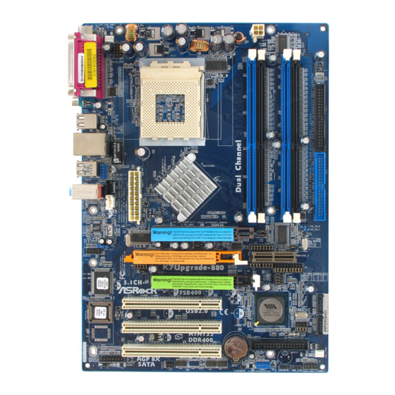
Page 8: 1.3 Motherboard Layout
Future CPU Bridge (K8BRIDGE_1) J5 / J4 Jumpers ( 2 sets of 8 x 2-Pin) Front Panel Audio Header (AUDIO1) J9 / J10 / J11 / J13 Jumper ( 5 sets of 1 x 3-Pin) JR1 / JL1 Jumpers Future CPU Bridge (K8BRIDGE_2) AGP Slot (1.5V_AGP1) -
Page 9: Asrock I/O Plus Tm
2 x USB 2.0 Ports (USB2, USB3) Line In (Light Blue) Serial Port: COM1 Line Out (Lime) PS/2 Keyboard Port (Purple) Microphone (Pink) PS/2 Mouse Port (Green) 2 x Shared USB 2.0 Ports (USB4, USB5) 9 9 9 9 9... -
Page 10: Installation Installation
Installation Installation Installation Installation K7Upgrade-880 is an ATX form factor (12.0-in x 8.5-in, 30.5 cm x 21.6 cm) motherboard. Before you install the motherboard, study the configuration of your chassis to ensure that the motherboard fits into it. Pre-installation Precautions... -
Page 11: Cpu Installation
CPU into the socket to avoid bending of the pins. Step 4. When the CPU is in place, press it firmly on the socket while you push down the socket lever to secure the CPU. The lever clicks on the side tab to indicate that it is locked. -
Page 12: Installation Of Memory Modules (Dimm)
(the same brand, speed, size and chip-type) DDR DIMM pair in the slots of the same color. In other words, you have to install identical DDR DIMM pair in Dual Channel A (DDR1 and DDR3; Blue slots; see p.8 No.7) or identical DDR DIMM pair in Dual Channel B (DDR2 and DDR4;... - Page 13 DIMMs or the system components. Step 1. Unlock a DIMM slot by pressing the retaining clips outward. Step 2. Align a DIMM on the slot such that the notch on the DIMM matches the break on the slot. notch break...
-
Page 14: Expansion Slots (K8 Bridge, Pci, And Agp Slots)
(K8 Bridge, PCI Slots, and AGP Slots) (K8 Bridge, PCI Slots, and AGP Slots) There are 1 set of K8 Bridge, 3 PCI slots, and 2 AGP slots (the slot 1.5V_AGP1 supports for K7 AGP Interface, and the slot AGP2 supports for K8 AGP Interface) on K7Upgrade-880 motherboard. - Page 15 NOTE When adjusting the jumper settings, you may use the tool, Jumper Cap Remover, to help you removing the jumper caps more easily. This Jumper Cap Remover is bundled in your motherboard package, and please follow the “Jumper Cap Remover Instruction” to use it properly.
-
Page 16: Jumpers Setup
FSB 200MHz FSB 400MHz Note: The setting of the CPU front side bus frequency of this motherboard is by means of the adjustment of jumper-setting. To perform over clocking, you must set the FSB jumper according to your AMD CPU before you use the “Manual” option as the FSB setting in... - Page 17 8.5x 9.5x 10.5x 11.5x 12.5x 13.5x 16.5x For example, “Athlon XP 2000+” is an 1666MHz CPU: 12.5 (Multiplier) X 133MHz (External frequency) = 1666MHz FID jumpers setting: FID4 FID3 FID2 FID1 FID0 The jumper caps are not provided by ASRock. Please understand that ASRock does not guarantee and support the adjustment of multiplier.
-
Page 18: Onboard Headers And Connectors
FLOPPY1 Pin1 (see p.8, No. 20) the red-striped side to Pin1 Note: Make sure the red-striped side of the cable is plugged into Pin1 side of the connector. Primary IDE Connector (Blue) Secondary IDE Connector (Black) (39-pin IDE1, see p.8, No. 9) (39-pin IDE2, see p.8, No. - Page 19 USB_PWR 6 ready-to-use USB 2.0 ports on (9-pin USB67) DUMMY the rear panel. If the rear USB (see p.8, No. 25) ports are not sufficient, this USB 2.0 header is available to USB_PWR support 2 extra USB 2.0 ports.
- Page 20 (see p.8, No. 24) Chassis Fan Connector Please connect the chassis fan cable to this connector and (3-pin CHA_FAN1) +12V match the black wire to the (see p.8, No. 21) CHA_FAN_SPEED ground pin. CPU Fan Connector Please connect the CPU fan...
-
Page 21: Serial Ata (Sata) Hard Disks Installation
STEP 3: Connect one end of the SATA data cable to the motherboard’s SATA connector. STEP 4: Connect the other end of the SATA data cable to the SATA hard disk. 2.8 Hot Plug and Hot Swap F Hot Plug and Hot Swap F... -
Page 22: Making An Sata Driver Diskette
2000 / Windows XP on your system directly without setting the RAID configura- tion on your system, or you may start to use “VT8237 SATA RAID BIOS” to set RAID 0 / RAID 1 / JBOD configuration before you install the OS. Before you start to configure the RAID function, you need to check the installation guide in the Support CD for proper configuration. -
Page 23: Bios Sbios Setup Utility Bios Setup Utility Etup Utility
Power-On-Self-Test (POST) to enter the BIOS SETUP UTILITY, otherwise, POST will continue with its test routines. If you wish to enter the BIOS SETUP UTILITY after POST, restart the system by pressing <Ctl> + <Alt> + <Delete>, or by pressing the reset button on the system chassis. -
Page 24: Navigation Keys
To jump to the Exit Screen or exit the current screen 3.2 Main Screen Main Screen Main Screen Main Screen Main Screen When you enter the BIOS SETUP UTILITY, the Main screen will appear and display the system overview BIOS SETUP UTILITY Advanced H/W Monitor Boot... -
Page 25: Advanced Screen
If you use an AMD 754-Pin CPU on the ASRock 754Bridge, which is installed into the K8 BRIDGE on this motherboard, you will see the below Main screen when entering the BIOS SETUP UTILITY. BIOS SETUP UTILITY Advanced H/W Monitor... -
Page 26: Cpu Configuration
Spread Spectrum This item should always be [Disabled] for better system stability. If you use an AMD 754-Pin CPU on the ASRock 754Bridge, which is installed into the K8 BRIDGE on this motherboard, you will see the below screens and configuration options for the CPU Configuration. - Page 27 It will display Processor Maximum Voltage for reference. Multiplier/Voltage Change This item is set to [Auto] by default. If it is set to [Manual], you may adjust the value of Processor Multiplier and Processor Voltage. However, it is recom- mended to keep the default value for system stability.
- Page 28 Memory Clock This item can be set by the code using [Auto]. You can set one of the standard values as listed: [133 MHz (DDR266)], [166 MHz (DDR333)], [200 MHz (DDR400)]. Flexibility Option The default value of this option is [Disabled]. It will allow better tolerance for memory compatibility when it is set to [Enabled].
-
Page 29: Chipset Configuration
[133MHz (DDR 266)], [166MHz (DDR 333)], [200MHz (DDR 400)]. Flexibility Option The default value of this option is [Disabled]. It will allow better tolerance for memory compatibility when it is set to [Enabled]. DRAM CAS# Latency Use this item to adjust the means of memory accessing. - Page 30 The default value of this feature is set to [Auto]. If you install an 8X-AGP card on this motherboard, you may select [Auto], [8X] or [4X] as the AGP mode. If the installed AGP card is a 4X-AGP card, then you may set the AGP mode as [Auto], [4X], [2X], or [1X].
- Page 31 The default value of this feature is set to [Auto]. If you install an 8X-AGP card on this motherboard, you may select [Auto], [8X] or [4X] as the AGP mode. If the installed AGP card is a 4X-AGP card, then you may set the AGP mode as [Auto], [4X], [2X], or [1X].
-
Page 32: Acpi Configuration
Use this item to enable or disable Ring-In signals to turn on the system from the power-soft-off mode. PCI Devices Power On Use this item to enable or disable PCI devices to turn on the system from the power-soft-off mode. PS/2 Keyboard Power On Use this item to enable or disable PS/2 keyboard to turn on the system from the power-soft-off mode. -
Page 33: Ide Configuration
[Disabled], [Primary], [Secondary], [Both]. IDE Device Configuration You may set the IDE configuration for the device that you specify. We will use the “Primary IDE Master” as the example in the following instruction, which can be applied to the configurations of “Primary IDE Slave”, “Sec- ondary IDE Master”, and “Secondary IDE Slave”... - Page 34 [ARMD]: This is used for IDE ARMD (ATAPI Removable Media Device), such as MO. LBA/Large Mode Use this item to select the LBA/Large mode for a hard disk > 512 MB under DOS and Windows; for Netware and UNIX user, select [Disabled] to disable the LBA/Large mode.
-
Page 35: Pcipnp Configuration
Exit v02.54 (C) Copyright 1985-2003, American Megatrends, Inc. PCI Latency Timer The default value is 32. It is recommended to keep the default value unless the installed PCI expansion cards’ specifications require other settings. PCI IDE BusMaster Use this item to enable or disable the PCI IDE BusMaster feature. -
Page 36: Super Io Configuration
Use this item to enable or disable floppy drive controller. Serial Port Address Use this item to set the address for the onboard serial port or disable it. Configuration options: [Disabled], [3F8 / IRQ4], [2F8 / IRQ3], [3E8 / IRQ4], [2E8 / IRQ3]. -
Page 37: Usb Configuration
OnBoard Game Port Use this item to enable the Game Port or disable it. OnBoard MIDI Port Use this itme to select the address for the MIDI Port or disable it. Configura- tion options: [Disabled], [300], and [330]. 3.3.8 3.3.8... -
Page 38: Hardware Health Event Monitoring Screen
Hardware Health Event Monitoring Screen Hardware Health Event Monitoring Screen In this section, it allows you to monitor the status of the hardware on your system, including the parameters of the CPU temperature, motherboard temperature, CPU fan speed, chassis fan speed, and the critical voltage. -
Page 39: Boot Settings Configuration
(C) Copyright 1985-2003, American Megatrends, Inc. Boot From Network Use this item to enable or disable the Boot From Network feature. Boot Up Num-Lock If this item is set to [On], it will automatically activate the Numeric Lock function after boot-up. 3.5.2 3.5.2... -
Page 40: Security Screen
Security Screen Security Screen 3.6 Security Screen Security Screen Security Screen In this section, you may set or change the supervisor/user password for the system. For the user password, you may also clear it. BIOS SETUP UTILITY Security Main Advanced... -
Page 41: Exit Screen
BIOS SETUP UTILITY. Discard Changes and Exit When you select this option, it will pop-out the following message, “Dis- card changes and exit setup?” Select [OK] to exit the BIOS SETUP UTILITY without saving any changes. Discard Changes When you select this option, it will pop-out the following message, “Dis-... -
Page 42: Install Operating System
This motherboard supports various Microsoft Windows operating systems: 98 SE / ME / 2000 / XP. Because motherboard settings and hardware options vary, use the setup procedures in this chapter for general reference only. Refer to your OS documentation for more information.