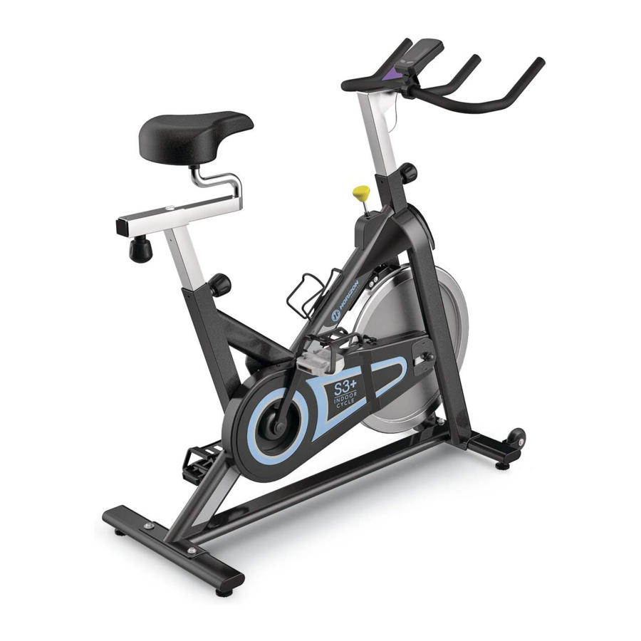
Horizon Fitness S3+, S3 - INDOOR CYCLE Manual
- Owner's manual (19 pages) ,
- Owner's manual (33 pages) ,
- Owner's manual (93 pages)
Advertisement
- 1 HOW TO MOVE THE DEVICE
- 2 LOCATION OF THE DEVICE
- 3 HOW TO ADJUST THE UNIT
- 4 TENSION CONTROL AND EMERGENCY BRAkE
- 5 MODEL INFORMATION
- 6 MAIN PARTS INCLUDED
- 7 PARTS PACKING INCLUDED
- 8 UNPACKING
- 9 ASSEMBLY INSTRUCTIONS
- 10 CONSOLE OPERATION
- 11 COMMON PRODUCT QUESTIONS
- 12 TROUBLESHOOTING
- 13 MAINTENANCE
- 14 EXPLODED VIEW
- 15 PARTS LIST
- 16 Documents / Resources
HOW TO MOVE THE DEVICE
Due to the weight of the Indoor Cycle, it is recommended that two persons move it. While one person lifts the back of the indoor cycle, the second person firmly holds the handlebar and tips the indoor cycle forward until it rolls on the wheels. Carefully move the Indoor Cycle to the desired location and then lower it.
If the Indoor Cycle rocks on the floor after being set down, turn the leveling feet underneath the front or rear stabilizer until the rocking motion is eliminated.

LOCATION OF THE DEVICE
Place the Indoor Cycle on a level surface. There should be 6 feet (183 cm) of clearance behind the Indoor Cycle, 3 feet (91 cm) on each side and 1 foot (30 cm) in front of the Indoor Cycle. Do not place the cycle in any area that will block any vent or air openings. The Indoor Cycle should not be located in a garage, covered patio, near water or outdoors.


To reduce the risk of injury, use extreme caution while moving the indoor cycle. Do not attempt to move it over uneven surfaces and make sure there's a safety space of 20 inch (minimum) to the nearest equipment is recommended.
HOW TO ADJUST THE UNIT
The Indoor Cycle can be adjusted for maximum comfort and exercise effectiveness. The instructions below describe one approach to adjusting the Indoor Cycle to ensure optimal user comfort and ideal body positioning; you may choose to adjust the Indoor Cycle differently.
SADDLE ADJUSTMENT
Proper saddle height helps ensure maximum exercise efficiency and comfort, while reducing the risk of injury. Adjust the saddle height to make sure it's in proper position, one that keeps a slightly bend in your knee while your legs are in the extended position.

HANDLEBAR ADJUSTMENT
Proper position for the handlebar is based primarily on comfort. Typically, the handlebar should be positioned slightly higher than the saddle for beginning cyclists. Advanced cyclists could try different heights to get the arrangement most suitable for you.
TO ADJUST THE SADDLE HEIGHT
Rotate the adjustment lever counterclockwise and adjust the saddle to a comfortable pedaling position. Rotate the lever clockwise to lock saddle position.

TO ADJUST THE SADDLE HORIZONTAL POSITION
Rotate the adjustment lever counterclockwise to slide the saddle forward or backward as desired. Rotate the lever clockwise to lock saddle position. Test the saddle slide for proper operation.
TO ADJUST THE HANDLEBAR HEIGHT
Rotate the adjustment lever counterclockwise to adjust the handlebar height. Raise or lower the handlebar to the desired height. Rotate the lever clockwise to lock handlebar position.

TO ADJUST THE PEDAL STRAPS
Place each foot ankle on the pedal and in the toe clip that the foot ankle is centered over the pedal spindle (center of the pedal). Rotate one foot to arms reach and pull up on the toe clip strap. Repeat for the other foot. Keep your knees over your feet as you pedal. To remove your foot from the toe clip, loosen the strap and pull out.
TENSION CONTROL AND EMERGENCY BRAkE
The preferred level of difficulty in pedaling (resistance) can be regulated in fine increments by use of the tension control knob. To increase the resistance, turn the tension control knob clockwise. To decrease the resistance, turn the knob counter clockwise.


- To stop the flywheel while pedaling, push down on the red emergency brake lever.
- The flywheel should quickly come to a complete stop.
- Make sure your shoes are fixed into the toe clip.
- Apply full resistance load when the bike is not in use to prevent injuries due to moving drive gear components.
The Indoor Cycle does not have a free moving flywheel; the pedals will continue to move together with the flywheel until the flywheel stops. Reducing speed in a controlled manner is required. To stop the flywheel immediately, push down the red emergency brake lever. Always pedal in a controlled manner and adjust your desired cadence according to your own abilities. Push the red lever down = emergency stop.
The Indoor Cycle uses a fixed flywheel that builds momentum and will keep the pedals turning even after the user stops pedaling or if the user's feet slip off. DO NOT ATTEMPT TO REMOVE YOUR FEET FROM THE PEDALS OR DISMOUNT THE MACHINE UNTIL BOTH THE PEDALS AND THE FLYWHEEL HAVE COMPLETELY STOPPED. Failure to follow these instructions may lead to loss of control and the potential for serious injury.
MODEL INFORMATION

MAIN PARTS INCLUDED
- 1 Main Frame
- Front & rear stabilizer
- Handlebar Set
- Seat Post Set
PARTS PACKING INCLUDED
- 1 Console box (S3+ only)
- 1 Parts box
- 1 Water bottle
- 1 Owners Manual
UNPACKING
Due to the weight of the indoor cycle, it is recommended that two persons perform the assembly. Set the indoor cycle in a cleared area and remove all packing materials; do not dispose of the packing materials until assembly is completed.
NOTE: During each assembly step, ensure that ALL nuts and bolts are in place and partially threaded in before completely tightening any ONE bolt.
NOTE: A light application of grease may aid in the installation of hardware. Any grease, such as lithium bike grease is recommended.
NEED HELP?
If you have questions or if there are any missing parts, contact your local dealer. Contact information may be located on the back panel of this manual or on warranty card.
ASSEMBLY INSTRUCTIONS
ASSEMBLY PARTS LIST

| ITEM | DESCRIPTION | QTY | SPECIFICATION |
| 1 | Handlebar | 1 | Chrome & PVC dipping |
| 2 | Seat Post | 1 | Chrome |
| 3 | Pedal (L) | 1 | Left threaded |
| 4 | Pedal (R) | 1 | Right threaded |
| 5 | Combination Wrench | 1 | |
| 6 | Allen Wrench | 1 | for 2 stabilizes |
| 7 | Allen Bolt | 4 | M8 x 16L |
| 8 | Washer | 4 | 8 |
| 9 | Front Base Frame | 1 | With 2 transportation wheels |
| 10 | Rear Stabilizer | 1 | Without 2 transportation wheels |
STEP 1
- Install the HANDLEBAR (1) into the frame receptor and secure with the knob.


Note: for assembling S3+ connect the upper and lower handlebar cable before install the handlebar.
STEP 2
- Install the STEP POST (2) into the frame receptor and secure with the knob.


STEP 3

- Thread the LEFT PEDAL (3) that has "L" on the spindle to the left side arm of the cycle using the COMBINATION WRENCH (5). Please note that the L pedal is left-hand threaded which needs to be turned counter clockwise to tighten.
- Thread the RIGHT PEDAL (4) that has "R" on the spindle to the right side arm of the cycle using the COMBINATION WRENCH (5). Please note that the R pedal is right-hand threaded which needs to be turned counter clockwise to tighten.
STEP 4
- Attach the FRONT BASE FRAME (9) to the frame using TWO ALLEN BOLTS (7) and TWO WASHERS (8), and secure firmly by ALLEN WRENCH (6).


STEP 5
- Attach the REAR STABILIZER (10) to the frame using TWO ALLEN BOLTs (7) and TWO WASHERs (8), and secure firmly by ALLEN WRENCH (6).


STEP 6

(S3+ ONLY)
- Install the MOUNTING CLAMP to the uppper handlebar with console screw and adjust the console angle.
Note: do not tighten the screw at this stage. - Carefully attach the SENSOR CABLE (a) connected to the frame to the LOWER CONSOLE CABLE (b)-located inside the handlebar assembly.
Note: Please ensure that the handlebar is located and locked at its lowest height adjustment position, this will allow access to the connecting cable inside the handlebar for both cables to be attached. - Once connected secure the cable to the upper internal frame of the RSH flywheel front forks, using the adhesive cable tidy pad. ( This is CABLE(a) which is preassembled to the lower frame.)
Note: Check to see there is no loose cable that could make contact with the flywheel once the cable harness is assembled.
STEP 7

(S3+ ONLY)
- Fix CONSOLE with console mounting clamp from the back.
- Carefully attach the UPPER CONSOLE CABLE to the LOWER CONSOLE CABLE preassembled to the HANDLEBAR.
- Once the console angle is adjusted tighten the screw on the mounting clamp fully.
STEP 8

- Congratulations, you have successfully assembled the Indoor Cycle.
- Please lubricate the seat post, brake pad and handlebar adjustment regularly with lubricant in your parts package and check the alignment of the sensor.
ASSEMBLY COMPLETE!
S3 / S3+
Max. User Weight: 130 kg / 286 lbs
Product Weight: 43 kg / 95 lbs.
Overall Dimension: 110 x 47 x 90 cm /43" x 19" x 35"
CONSOLE OPERATION
CONSOLE DISPLAY

S3+
MONITOR DISPLAY:
At the exercise mode, the LCD windows will display RPM, KCAL and ODO.
You can press left Key to change the display among TIME/SPEED/CLOCK/DISTANCE
LEFT & RIGHT KEY:
- Press any key to wake up the console from energy saver mode.
- During the exercise mode, press left change display among TIME/SPEED/CLOCK/DISTANCE.
CLOCK SETTING
S3+
Press the left key until CLOCK is displayed, press the right key for 3 seconds to enter setting mode to adjust clock setting.
Change the value by pressing right key and confirm by pressing left key, the console will automatically save the value given after 5 seconds.
PERSONAL WORKOUT DATE SETTING
S3+
Press the left key until SPEED is displayed, press the right key for 3 seconds to adjust personal data setting.(user weight, gender and workout time etc.)
Change the value by pressing right key and confirm by pressing left key, the console will automatically save the value given after 5 seconds.
ENERGY SAVER
S3+
To minimize energy consumption, your machine will enter energy saver mode automatically when not in use and could be quickly waken up with a touch of a button.
COMMON PRODUCT QUESTIONS
ARE THE SOUNDS MY DEVICE MAKES NORMAL?
Our Indoor Cycles are some of the quietest available because they use belt drives and cantilever brake resistance. We use the highest grade bearings and chains/belts to minimize noise. However, because the resistance system itself is so quiet, you will occasionally hear other slight mechanical noises. Unlike older, louder technologies, there are no fans, friction belts, or alternator noises to mask these sounds on our Indoor Cycles. These mechanical noises, which may or may not be intermittent, are normal and are caused by the transfer of significant amounts of energy to a rapidly spinning flywheel. All bearings, chains/belts and other rotating parts will generate some noise which will transmit through the casing and frame. It is also normal for these sounds to change slightly during a workout and over time because of thermal expansion of the parts.
WHY IS THE Indoor Cycle I HAD DELIVERED LOUDER THAN THE ONE AT THE STORE?
All fitness products seem quieter in a large store showroom because there is generally more background noise than in your home. Also, there will be less reverberation on a carpeted concrete floor than on a wood overlay floor. Sometimes a heavy rubber mat will help reduce reverberation through the floor. If a fitness product is placed close to a wall, there will be more reflected noise.
HOW LONG WILL THE BELT LAST
The computer modeling we have done indicated virtually thousands of maintenance free hours. You should not have to replace the belt as long as you have the Indoor Cycle.
CAN I MOVE THE Indoor Cycle EASILY ONCE IT IS ASSEMBLED?
Your Indoor Cycle has a pair of transport wheels built into the front stabilizer tube. Please follow the moving the Indoor Cycle section to transport your Indoor Cycle. It is important that you place your Indoor Cycle in a comfortable and inviting room. Your Indoor Cycle is designed to use minimal floor space. Many people will place their Indoor Cycles facing the TV or a picture window. If at all possible, avoid putting your Indoor Cycle in an unfinished basement. To make exercise a desirable daily activity for you, the Indoor Cycle should be in a comfortable setting.
TROUBLESHOOTING
The device makes a squeaking or chirping noise
Verify the following:
- The Indoor Cycle is on a level surface.
- Loosen all bolts attached during the assembly process, grease the threads, and tighten again.
If this does not remedy the problem, you may
CONTACT CUSTOMER TECH SUPPORT AT THE NUMBER ON THE INFORMATION CARD.
The following information may be asked of you when you call. Please have these items readily available:
- Model Name
- Serial Number
- Proof of Purchase (receipt or credit card statement)
You may find more troubleshooting suggestions on the customer support section of our website. Contact customer support using the contact information on the INFORMATION CARD.
In order for Customer Tech Support to service your Indoor Cycle they may need to ask detailed questions about the symptoms that are occurring. Some troubleshooting questions that may be asked are:
- How long has this problem been occurring?
- Does this problem occur with every use? With every user?
- If you are hearing a noise, does it come from the front or the back? What kind of noise is it (thumping, grinding, squeaking, chirping etc.)?
- Has the machine been lubricated and maintained per the maintenance schedule?
Answering these and other questions will give the technicians the ability to send proper replacement parts and the service necessary to get you and your Indoor Cycle running again!
MAINTENANCE
The safety level given by the design of the Indoor Cycle can only be maintained when the equipment is regularly examined for damage and wear. Inoperable components should be replaced or the equipment should be put out of use until it is repaired.
DAILY
- Wipe down the Indoor Cycle after each use to remove sweat and moisture. Use soap and water, or a diluted non-abrasive domestic cleaner solution. Rinse to remove detergent residue and then dry off.
- Before each session, inspect for loose components such as pedals or cranks prior to commencing the next use. Tighten up any loose parts.
WEEKLY
- Check for proper flywheel alignment. Torque flywheel nuts as necessary.
- Remove chain guard and check for loose chain. Adjust and lubricate the chain as necessary.
- Check to make sure the crank arms are tight to the bottom bracket.
- Inspect all parts, nuts, bolts, or screws for adjustments, replacements or maintenance.
MONTHLY
- Inspect the frame and main assembly components for rust or corrosion. Tilt the cycle or place in an upside down position to locate areas where rust and corrosion may develop. Use a small, wire brush to remove rust build-up in small crevasses, such as leveling feet, quick release levers and other bolt assemblies.
- Inspect all wear items for adjustments or possible part replacement. Give particular attention to the following:
- Inspect brake pad for wear. Excessive wear or dryness indicates replacement is required.
- Inspect seat pad for wear. Rips, tears or excessive movement indicates replacement is required.
- Inspect pedals for play. Excessive movement of pedals indicates replacement is required.
- Inspect the chain for tensioning by rotating the crank to drive the flywheel forward. Do this motion in 1/4 turns to assess if there is free play between the crank and the flywheel.
- Dryness or prolonged use may cause the height and reach adjustments for the seat and handlebar to become tight. If this is the case, the sliding assembly should be removed from the frame and have a smear of light duty grease applied along the sliding surface before assembly. Similarly, apply some light grease to the clamping assembly to ensure it does not seize up. Clean off excessive grease before reassembly.
- Please lubricate the seat post, brake pad and handlebar adjustment regularly with lubricant in your parts package.
EXPLODED VIEW

S3 EXPLODED VIEW

S3+ EXPLODED VIEW
PARTS LIST
S3 & S3+ PARTS LIST


Documents / ResourcesDownload manual
Here you can download full pdf version of manual, it may contain additional safety instructions, warranty information, FCC rules, etc.
Advertisement
Thank you! Your question has been received!


Need Assistance?
Do you have a question about the S3+ that isn't answered in the manual? Leave your question here.