Table of Contents
Advertisement
Quick Links
[ 1 ] PRODUCT OVERVIEW . . . . . . . . . . . . . . . . . . . . . . . . . . . . . . . . . . . . . . . 1
[ 2 ] SPECIFICATIONS . . . . . . . . . . . . . . . . . . . . . . . . . . . . . . . . . . . . . . . . . . . . 1
[ 3 ] UNPACKING AND INSTALLATION . . . . . . . . . . . . . . . . . . . . . . . . . . . . . . 1
[ 4 ] COMPONENT IDENTIFICATION . . . . . . . . . . . . . . . . . . . . . . . . . . . . . . . . 5
[ 5 ] OPERATIONAL DESCRIPTIONS . . . . . . . . . . . . . . . . . . . . . . . . . . . . . . . 7
[ 6 ] DISASSEMBLY, ASSEMBLY AND ADJUSTMENTS . . . . . . . . . . . . . . . . 15
[ 7 ] CONNECTOR LAYOUT . . . . . . . . . . . . . . . . . . . . . . . . . . . . . . . . . . . . . . 20
[ 8 ] MAINTENANCE . . . . . . . . . . . . . . . . . . . . . . . . . . . . . . . . . . . . . . . . . . . . 21
[ 9 ] ELECTRIC DESCRIPTIONS . . . . . . . . . . . . . . . . . . . . . . . . . . . . . . . . . . . 22
[10] CIRCUIT DIAGRAM . . . . . . . . . . . . . . . . . . . . . . . . . . . . . . . . . . . . . . . . . 33
PARTS GUIDE
Parts marked with "!" is important for maintaining the safety of the set. Be sure to replace these parts with specified
ones for maintaining the safety and performance of the set.
SERVICE MANUAL
CONTENTS
SHARP CORPORATION
CODE: 00ZSFA55SM//E
SF-A55
MODEL
This document has been published to be
used for after sales service only.
Advertisement
Table of Contents

Related Manuals for Sharp SF-A55


Summary of Contents for Sharp SF-A55
-
Page 1: Table Of Contents
SERVICE MANUAL CODE: 00ZSFA55SM//E SF-A55 MODEL CONTENTS [ 1 ] PRODUCT OVERVIEW ........1 [ 2 ] SPECIFICATIONS . -
Page 2: 1 ] Product Overview
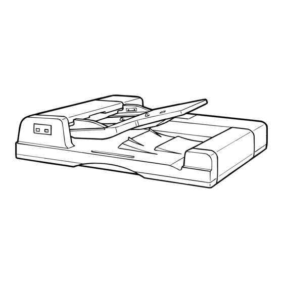
[1] PRODUCT OVERVIEW [3] UNPACKING AND INSTALLATION The SF-A55 is a reversing automatic document feeder (RADF). The SF-A54 can be used with the copier SF-2050. The SF-A55 is capable 1. Unpacking of automatically copying both sides of document by inverting the document sheets up-side down, while feeding them. - Page 3 Unplug the copier and follow the procedure below. (2) Adjust the angle of ADF. Loosen the two fixed screws for the angle adjusting panel which are (1) Mount the ADF onto the copier. located on the hinge angle and then fasten the loosened screws while Remove the 2 cut-outs from the upper cabinet panel of the copier.
- Page 4 (4) Connect the ADF tray connector. (7) Adjust the center of the copy. Open the ADF cover and connect the ADF connector to the tray Set the original on the tray and make a copy. When the copy slips out connector.
- Page 5 • Setup example (1) If the lead edge of the original was still not to the stopper, enter an optimum value. Original Stopper Glass (2) If the image at the lead edge of the original were to deform, enter an optimum value to move to the glass side. Original Stopper Glass...
-
Page 6: 4 ] Component Identification
[4] STRUCTURE A. External fitting C. PWB distribution Original guide Control PWB Reverse original Original set tray Lead switch PWB Original feed cover detector PWB Original end Original transport cover sensor 2 PWB Display lamp Original detector PWB Original exit section cover Original timing B. - Page 7 E. Sensors, switches, detectors DWS4 DWS3 AUOD DTMRS DWS2 DLS2 DWS1 DLS1 DFMRS DED1 DED2 TGOD FGOD Code Name Type Function, operation Contact, output Original feed sensor Reflection sensor Turns HIGH when the original lead edge is fed HIGH when the original is just in front of the resist roller.
-
Page 8: 5 ] Operational Descriptions
[5] OPERATIONAL DESCRIPTIONS ↓ Step 13: Paper feed motor (DFM) forward rotation (MECHANISM SECTION) (Resist roller rotation) The lead edge of original is taken up with the resist roller. A. ADF mode (Single mode) operation ... - Page 9 ↓ ↓ Step 43: Transport motor (DTM) OFF * D Step 28: The original is stopped by the original (Transport belt, reverse roller, paper exit roller stopper. stop) Transport motor (DTM) OFF ...
- Page 10 * A: This operation is performed when there is an original NOTE: ↓ on the original table in advance. If there is no Step 57: Reverse original sensor (RDD) senses the original on the original table, this operation is not ...
- Page 11 2) RADF (duplex mode) copy in the SF-A55 ↓ Step 18: Transport motor (DTM) forward rotation START (Transport roller, reverse roller, paper exit ↓ roller rotation) Step 01: The transport section is closed. (AUOD ON) ↓...
- Page 12 ↓ ↓ Step 35: The copier mirror base scanning is started. Step 53: The original is stopped by the original ↓ stopper. HIGH (No original on the tray) → AFter Transport motor (DTM) OFF completion of scanning of the mirror base, go to (Transport roller, reverse roller, paper exit output...
- Page 13 ↓ ↓ Step 73: Reverse original sensor (RDD) senses the Step 91: Transport motor (DTM) OFF lead edge of the original. (Transport roller, reverse roller, paper exit (RDD output: LOW) roller stop) ↓...
- Page 14 Sensor status by document size C. Detection of document size F: ON or L output (sensed) Document size is sensed in either of three ways, which correspond to Document size, setting : OFF or H output a different operation. orientation DWS1 DWS2 DWS3 DWS4 DLS1 DLS2 1) Sensing of document size by the document set tray...
- Page 15 2) Sensing of document size by the document width sensor (DWS) in the feed section Sensing of document size by the document width sensor is used, in automatic paper size and automatic magnification selection mode, to determine whether the document is A4 or A5 (11" x 8.5" or 8.5"...
-
Page 16: 6 ] Disassembly, Assembly And Adjustments
3) Sensing of document size by feed motor rotation sensor (DFMRS) 1. External components This function compensates for the inaccuracy of the document size recognition in the document tray when document sheets of maintenance cover different sizes are stacked in the document tray. Consequently, Feeder cover results of this function is preferred over the document size recog- nition in the document tray. - Page 17 3. Mounting and adjustment of separator Hex. socket head screw unit Separator unit Mount the separator pulley assembly on the separator bracket while keeping a clearance of 0.1mm between the collar 4 and the bearing as shown below. Secure the 0.1mm clearance by using a spacer of 0.1mm thick and clamping the collar 4 with a hex.
- Page 18 e. Remove the E ring, separator pulley drive gear and bearing (AB series) (w/one-way attachment), and slide the shaft in the direction of Screw arrow shown in the figure to remove it. Screw (Inch series) Empty sensor Rear bearing (Wait shaft) Screw Bearing Lever...
- Page 19 l. Unscrew four screws to remove the lower paper feed guide. 6. Removing the resist roller m. Unscrew the follow set screw to remove the front side collar of the Remove the document tray and the transfer cover. feed roller shaft. On the rear side, remove the E ring and the bearing and switch back the feed roller shaft to remove it upward.
- Page 20 f. Remove the two original belt counter roller assys, and the original 8. Installation of inverting section, feed feed belt. section clock pulleys After securing the transfer motor on the motor bracket, set the clock Bushing pulley on the motor shaft. Clamp the clock pulley with two hex. socket head screws while securing a space of 0.5±0.2mm between the end Original feed belt faces of the pulley and the motor.
-
Page 21: 7 ] Connector Layout
• Setup example [7] CONNECTOR LAYOUT (1) If the lead edge of the original was still not to the stopper, enter an optimum value. 1. Connections around control circuit (2) If the image at the lead edge of the original were to deform, board enter an optimum value to move to the glass side. -
Page 22: 8 ] Maintenance
4. Connection in feed section (Front side) [8] MAINTENANCE Feed guide open/close switch 1. Replacement parts ASM-A open SW DWG No. Part name Separator belt Transfer belt Gate solenoid ASM-A drive 5. Invertor exit section (Front side) 2. Maintenance parts Inverter guide open/close switch Clean the following parts in the specified methods during main- tenance service. -
Page 23: 9 ] Electric Descriptions
[9] CIRCUIT DESCRIPTIONS 1. General This circuit controls feeding, transporting, stopping, and reversing of the original. It is composed of sensors, switches, the circuit which processes signals from the copier PPC, the circuit which drives motors, solenoids, and clutches, the CPU, the G/A and it peripheral circuits. 2. - Page 24 3. Operational descriptions A. Sensor/detector input circuit [a] Original feed sensor (DFD) Original feed sensor CN1 -16 +5 V TLN119 IC5-3 CN1 -14 DFDL ED B4B-PH-K-S R8 4 D-A2 PH110M CN13-4 +5 V C1 0 R113 VOUT CN13-3 R135 LE D CN13-2 R110 TP71...
- Page 25 [c] Original timing sensor (DTD) +5 V DA 3 R116 Reverse timing sensor R112 TP70 B3B-PH-K-S R9 4 R7 8 R133 LE D CN1 2-1 CN1 -10 DTDLED R3 9 P62/INT3 VOUT CN1 2-2 CN1 -11 SGND TP10 SGND CN1 2-3 CN1 -12 SGND C4 8...
- Page 26 [e] Paper feed motor rotation sensor (DFMRS), transport motor rotation sensor (DTMRSA) input circuit TLP1215(C1) TP49 DF3-8P-2DSA 4.7K Transport motor Constant voltage CN11.4 CRG10G472J power rotation sensor VOUT CN11.5 DTMRSA 4.7K CN11.6 SGND DTMRSA CRG10G472J (To the paper feed motor speed control circuit) 3300pF CRM40B332K50PT...
- Page 27 [g] Original set detector (DED), original width sensor (DWS) input circuit TLP1215(C1) CN20 TP32 DF11-28DP-2DSA 4.7K Original set Constant voltage CN1.17 CRG10G472J power sensor VOUT CN1.18 P0/MP0 4.7K 4.7K CN1.19 SGND CRG10G472J CRG10G472J 3300pF CRM40B332K50PT Original sensor input circuit TLP1217(C2) CN15 TP33 DF11-28DP-2DSA...
- Page 28 B. Motor control circuit [a] Paper feed motor (DFM) speed control circuit TP67 VCC-DC+24V VDD-+5V GND-GND Fref Fsig TP24 FGin DFMRS R125 TP25 R139 R124 R141 TP41 R137 EA + M1PWM R136 Fead IC12.6 IC5-1 Test Dead R138 ZD 8 TP40 PWM8 Motor control circuit...
- Page 29 Block diagram TC9192AF (IC9 internal circuit) Fref Phase Voltage control waveform comparison oscillator unit 10 Vro Fsig 1/2560 dividing unit 8 APC 1/20 dividing 1/256 dividing unit 8bit D/A unit convertor 1/2FG 12 R/S Speed monitor Lock range & dividing Timing dividing unit detection reverse detection...
- Page 30 Output control Reference Low input erroneous Refout voltage input operation preventing circuit circuit Oscillation circuit PWM output Dead time comparator Dead time control PWM output Error amplifier 1 PWM comparator Non-reverse input Reverse input Non-reverse input Reverse input Error amplifier 2 Feedback IC8 internal circuit (C) PWM circuit...
- Page 31 [b] Paper feed motor (DFM)/transport motor (DTM) drive circuit TP60 TP62 TP59 TP61 TP58 M1H 1 OUT1-1 M1L1 OUT1-2 DFM2 CN5-4 M1H2 OUT2-1 Paper feed motor M1L2 OUT2-2 DFM1 CN5-3 CHGCLK +24V VCC2 VCC1-1 VCC1-2 PG1 PG2 TP55 TP57 TP54 TP56 PGND M2H1 OUT1-1...
- Page 32 [c] Current limiting circuit (From motor drive circuit) TP48 TP27 IC2-3 R118 R117 M1CUR R119 +24V M2CUR R120 R147 R140 PGND PGND Current limiting circuit This circuit limits the starting current, and is composed of the current value detecting resistor and the voltage comparator. The negative potential side of each motor is connected to the pick-up resistor of R117, R118, R119, and R120.
- Page 33 D. Other circuits [a] EEPROM (IC10) circuit E2ROM5V R130 R129 R114 P40/AN0 R128 P63/PRDY IC16 R127 P64/A0 R126 P65/CS TEST EEPROM circuit This memory stores the sensitivity data of the reflection sensors, the set position data of the originals on the original glass, and the counter values such as the original pass count.
-
Page 34: [10] Circuit Diagram
[10] CIRCUIT DIAGRAM A. Circuit Diagram The parts in (----) are not actually installed. (Exept for oscillators OSC1 adn OSC2.) R5 3 TP 4 R5 2 R7 1 R2 8 R2 7 IC12.1 R7 0 17 7 P67/W CN7-2 TX D1 P34/Rxd CN7-3 RXD1... - Page 35 PWB-C DF3-6S-2C HC system V0.5-3 ASM t ray grounding C 176764-1 (176758-1), #18, #20 ASM tray grounding I (DF3-2428SCF ) PBA-control Green Green PCB- 176762-1 (176759-1), #26 SG N D CN7-1 HI sys tem lead switc h Green PWB-S N.C. CN33-1 V0.5-3 Purple...
- Page 36 C. Control PWB – 37 –...
- Page 37 D. Lead switch PWB E. LED PWB F. Sensor PWB1 G. Sensor PWB2 – 38 –...