Table of Contents
Advertisement
Quick Links
Advertisement
Table of Contents

Related Manuals for Danfoss GX-850M


Summary of Contents for Danfoss GX-850M
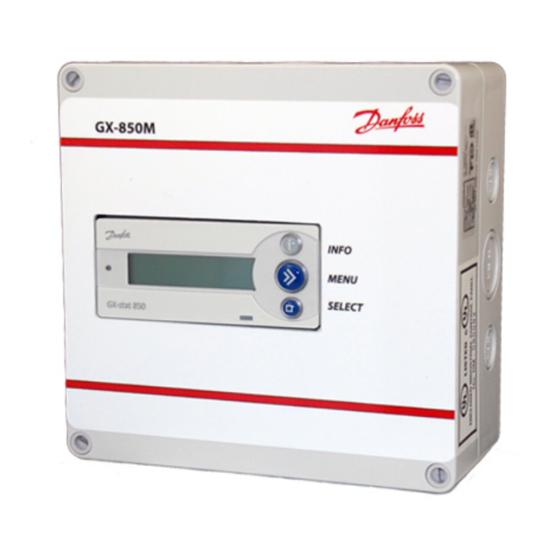
- Page 1 Installation Instruction Danfoss GX-850M ver. IV Automatic Control Panel...
-
Page 2: Table Of Contents
Roof system ........... . 35 2 | © Danfoss | 2018.10... -
Page 3: 1: User Manual
User Manual System overview The GX-850M ver. IV system is capable of keeping outdoor areas free of ice and snow. The GX-850M ver. IV can handle up to 2 independent areas, in any of the following combinations: • Single roof system... - Page 4 GX-850M ver. IV When more than 1 area is controlled by the GX-850M ver. IV system, it is also possible to prioritize the areas. Prioritizing makes it possible to operate 2 areas, even if the required power for 2 areas is not present.
-
Page 5: General Use
The GX-850M ver. IV can simultaneously control up to 2 different systems. These 2 systems are referred to as System A and System B. The GX-850M ver. IV gives the user the opportunity to view the current status of the systems. The status can be shown in 2 different ways. -
Page 6: Menu System
The user can always press to get more information about the current status irrespective of view selected. Menu system The menu system is navigated by the keys No matter if the GX-850M ver. IV controls ... -
Page 7: Possible Alarms During Operation
- Contact your local installer to get a replacement. New sensor added Description: When a new sensor is added, the GX-850M ver. IV alerts the user and at the same time automatically switches to “Constant Off” mode. User interaction is needed in order to correct the error. -
Page 8: Changing Parameters And Performance Of Systems
Priority When using the GX-850M ver. IV as a dual or combi system, it is possible to prioritize the systems. When the priority of 2 systems is equal, both systems can heat at the same time. If the priority of the 2 systems differs, and both systems want to heat, only the system with the highest priority is allowed to heat. -
Page 9: Ground System
Priority When using the GX-850M ver. IV as a dual or combi system, it is possible to prioritize the systems. When the priority of 2 systems is equal, both systems can heat at the same time. If the priority of the 2 systems differs, and both systems want to heat, only the system with the highest priority is allowed to heat. -
Page 10: 2: Installer Manual
(2 systems, 2-4 sensors total, minimum 1 sensor per system) When more than 1 area is controlled by the GX-850M ver. IV system, it is also possible to prioritize the areas. Prioritizing makes it possible to operate 2 areas, even if the needed power for 2 areas is not pre- sent. -
Page 11: Placement
When wiring up the GX-850M ver. IV and sensors, please be aware of the following conditions: When the GX-850M ver. IV is used in a dual system configuration, it is preferable that each sen- sor bus (Devibus™) can be connected and disconnected via switches. During the installation of a dual system, each system must be connected one at a time. - Page 12 120VAC External Supply The dry contact relays A and B inside the GX-850M ver. IV are used to switch to the voltage of your choice. (120VAC Maximum). The diagrams on the opposite page show typical applications. (The ground wire is not shown).
- Page 13 Installation Instruction GX-850M ver. IV Typical Applications Electric Snow Melting- Loads Greater than 15A BLACK WHITE WHITE 24 VDC GX-stat 850 Vout Adj. DC LO DC ON Alarm System A System B AC IN Load Contactor Coil 120 VAC External Supply...
- Page 14 The installation shall be in accordance with the manufacture’s instructions and national and local electrical codes. The installation shall be in accordance with part 426, American National Standard Institute / National Fire Protection Association (ANSI/NFPA70), National ElectricalCode (NEC) and Canadian Electrical Code (CEC), part 1 14 | © Danfoss | 2018.10 VUAPA422...
- Page 15 GX-850M ver. IV Part Numbers GX Snow Melting Controls Part # Description Voltage 088L3415 GX-850M ver. IV Automatic Control Panel 120V GX-850M ver. IV Automatic Control Panel GX Snow Melting Accessories Part # Description 088L3051 Ground Sensors (Two per Package)
-
Page 16: Installation Steps For System/Systems
Installation steps for system/systems The installation of the GX-850M ver. IV is very easy, and the user is guided through the installation process. The installation process differs a little depending on which kind and the number of systems to be installed. -
Page 17: Installation Of Roof System
Installation of roof system The installation of a GX-850M ver. IV with 1 roof system has been selected. It is optional if the sensors are connected to the GX-850M ver. IV before power on or during the installation. The system uses the output System A. -
Page 18: Installation Of Ground System
Installation of ground system The installation of a GX-850M ver. IV with 1 ground system has been selected. It is optional if the sensors are connected to the GX-850M ver. IV before power on or during the installa- tion. The system uses the output System A. -
Page 19: Installation Of Combination System
Installation of combination system The installation of a GX-850M ver. IV with 1 roof system and 1 ground system has been selected. It is optional if the sensors are connected to the GX-850M ver. IV before power on or during the installation. - Page 20 (Naming sensors, changing factory settings and setting priorities) Please refer to “Changing parameters and performance of systems” in “User Manual” for description of the configurable parameters. Press to end Configuration. Press to end configuration. 20 | © Danfoss | 2018.10 VUAPA422...
-
Page 21: Installation Of Dual System
The installation of a GX-850M ver. IV with 2 roof systems or 2 ground systems has been selected. It is mandatory that no sensors or only sensors for System A are connected to the the GX-850M ver. IV before power up. Sensors for System B must be connected to the GX-850M ver. IV during the installa- tion steps. - Page 22 (Naming sensors, changing factory settings and setting priorities) Please refer to “Changing parameters and performance of systems” in “User Manual” for description of the configurable parameters. Press to end Configuration. Press to end configuration. 22 | © Danfoss | 2018.10 VUAPA422...
-
Page 23: Modification Of System(S)
Installation Instruction GX-850M ver. IV Modification of system(s) It is possible to modify the installed systems on the GX-850M ver. IV. The following modifications are pos- sible: • Reactivate passive sensors • Replace a malfunctioning sensor • Add an extra sensor When the GX-850M ver. - Page 24 Cancel add Press when the correct new sensor to add is found or “Cancel add sensor? sensor?” is selected. Sensor added! If the user selected a new sensor to add, the sensor is added. 24 | © Danfoss | 2018.10 VUAPA422...
-
Page 25: 3: Technical Specification
Lit info key (yellow) Measurements: (Depth x Height x Width) • GX-850M ver. IV (without enclosure) 2.09” (53 mm) x 3.39” (86 mm) x 4.13” (105 mm) • Roof sensor(s) 0.6” (15 mm) x 0.93” (23.5 mm) x 8.5” (216 mm) •... -
Page 26: Factory Settings (Roof System)
-4°F (-20°C) to 32°F (0°C) Melting temperature 39°F (4.0°C) 34°F (1°C) to 50°F (10°C) Post-heat 1 hour 0 to 9 hours Clogged drain On/off System mode Automatic • Automatic • Constant ON (manual timer) • Manually OFF 26 | © Danfoss | 2018.10 VUAPA422... -
Page 27: 4: Appendix
Installation Instruction GX-850M ver. IV Appendix A: Menu system Main menu System ... - Page 28 28 | © Danfoss | 2018.10 VUAPA422...
- Page 29 Installation Instruction GX-850M ver. IV Installer menu Installer menu ...
- Page 30 30 | © Danfoss | 2018.10 VUAPA422...
- Page 31 Installation Instruction GX-850M ver. IV View statistic View statistics ...
-
Page 32: B: How It Works
If the reason for ending a heating period is a decrease of moisture to below the chosen level the post- heating period will start. Post-heating ensures that no ice and snow is left on the roof. 32 | © Danfoss | 2018.10 VUAPA422... -
Page 33: Ground System
Installation Instruction GX-850M ver. IV Ground system The ground system is fully automated. Temperature < Standby tempera- Standby Standby ture It gathers information on moisture and Temperature >- (No heating) Mantaining standby Standby tempera- temperature via digital sensors continu- ture temperature Temperature <... -
Page 34: Security And Energy Consumption
This will give relatively low energy consumption, but the area may remain wet and icy in short periods. The factory settings are average values providing a relatively high degree of security and moder- ate energy consumption. 34 | © Danfoss | 2018.10 VUAPA422... -
Page 35: C: Sensor Cable Extension
Installation Instruction GX-850M ver. IV C: Sensor cable extension Ground system 1 pcs. PSU 24V Number of sensors: 1 or 2 Cable type Max. length (m) Max. length (m) Max. length (m) 16 AWG (1 mm²) 985’ (300) 492’ (150 m) 262’... - Page 36 The acceptance of the order confirmation by the purchaser includes the acceptance of our “General Conditions of Sale and Warranty” as the only ruling condition. No modification of these conditions will be recognized by Danfoss. Any express or implied condition, statement or warranty, statutory or otherwise - not stated herein is excluded.
- Page 37 The Danfoss Guarantee is granted to: Name: Address: Postal code: Phone: Important! In order to obtain the Danfoss Guarantee, the following must be carefully filled in. See other conditions on previous page. Electrical Installation by: Installation date: Type of thermostat: Production code:...
- Page 38 Installation Instruction GX-850M ver. IV Notes 38 | © Danfoss | 2018.10 VUAPA422...
- Page 39 Installation Instruction GX-850M ver. IV Notes VUAPA422 © Danfos 2018.10 | 39...
- Page 40 Danfoss Heating Solutions 11655 Crossroads Circle Baltimore, MD 21220 Phone: 1-888-326-3677 Option 3 Fax: 416-352-5981 Email: heating.ts.electric.na@danfoss.com www.heating.danfoss.us VUAPA422 40 | © Danfoss 2018.10...