Advertisement
Quick Links
Advertisement

Related Manuals for Yamaha CobraNet MY16-C


Summary of Contents for Yamaha CobraNet MY16-C
- Page 1 INTERFACE CARD MY16-C Owner’s Manual...
- Page 2 The above statements apply ONLY to those products distributed by Yamaha Corporation of America or its subsidiaries. * This applies only to products distributed by YAMAHA CORPORATION OF AMERICA.
- Page 3 • Before installing the MY16-C in an audio device please check to make sure that the device is compatible with the MY16-C, and check possible restrictions regarding the maximum number of Yamaha and third-party expansion cards that can be simultaneously installed.
-
Page 4: Table Of Contents
MY16-C Card Installation Procedure ........15... -
Page 5: About Cobranet
Audio is transmitted over the CobraNet network in units known as “bundles.” These bundles are processed at the receiving end to reconstitute the original audio signals. In the case of the MY16-C a bundle can contain from 3 to 8 channels. Each bundle is identified by a number from 0 to 65,279, and audio transmission via the network becomes possible when the same bundle number is specified at both the transmitting and receiving devices. - Page 6 A (device D in this example). CobraNet Device CobraNet Device Network CobraNet Device CobraNet Device CobraNet Device CobraNet Device Network CobraNet Device CobraNet Device MY16-C Owner’s Manual Digital Audio Data Digital Audio Data...
- Page 7 The conductor for the network is automatically assigned and need not be specified by the operator. When an MY16-C is assigned to be the conductor for the network, the LED indicator to the right of the connector that is connected to the network will light orange. If the conductor fails for some reason, conductor status is automatically switched to another device on the network.
-
Page 8: The My16-C System
The MY16-C System The internal signal flow of the MY16-C is shown in the illustration below. 16 audio inputs and 16 audio outputs are available, and for this example channels 1 ~ 8 are bundle 1, and channels 9 ~ 16 are bundle 2. -
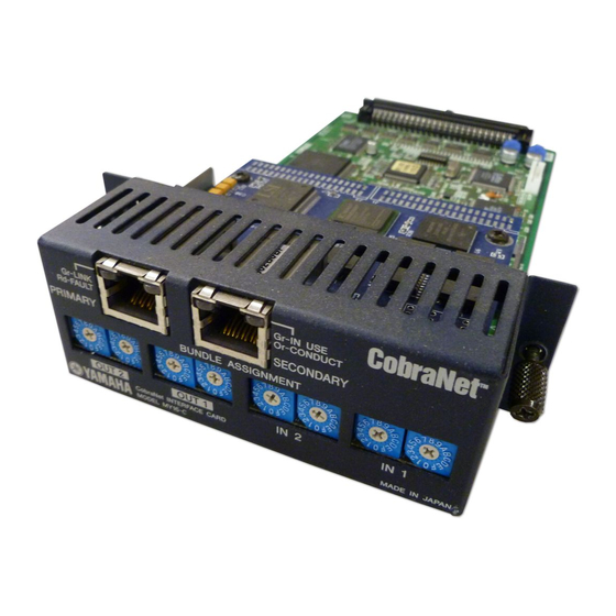
Page 9: Controls & Functions
The indicator will go out if a cable, hub, or other device connected to the network has failed. If the indicator remains lit or flashing even after the cable is disconnected, there may be a fault in the MY16-C card itself. In this case please refer the problem to qualified Yamaha service personnel. 4 [IN USE/CONDUCT] Indicators These are the indicators to the right of the [PRIMARY] and [SECONDARY] connectors. - Page 10 No serial control transmission occurs if this switch is set to “0”. When adjusting rotary switches please use a screwdriver with a blade that matches the switch groove. Attempting to use a screwdriver that is too large or too small can damage the switch. MY16-C Owner’s Manual...
- Page 11 ■ DIP Switches The DIP switches on the MY16-C circuit board can be used to set audio resolution, latency, the clock synchronization mode, and clock frequency. All dip switches are OFF when the MY16-C is initially shipped. n The RESERVED 1 and RESERVED 2 switches are reserved for functions to be implemented in the future.
- Page 12 See "Clock Synchronization Modes" on page 12 for more information. CLOCK 1 LATENCY 2 LATENCY Reserved CLOCK 2 Clock Synchronization Mode Network synchronization Host synchronization 1 Host synchronization 2 Reserved 5.33 ms 2.67 ms 1.33 ms MY16-C Owner’s Manual...
-
Page 13: Clock Synchronization Modes
Non-network Device Host Synchronization 1 Use this mode if the device in which the MY16-C is installed is synchronized to a clock signal other than the CobraNet clock. When the Host Synchronization 1 mode is selected the MY16-C receives synchronization from the device in which it is installed (the "host"), and that clock signal is then supplied to the network. - Page 14 Host Synchronization 2 Use this mode if the MY16-C card is to be synchronized to the clock signal from another MY16-C card installed in the same device. When more than one MY16-C cards are installed in the same device and synchronization is to be received from the CobraNet network, set one of the installed MY16-C cards to Network Synchronization, and the other card(s) in the same device to Host Synchronization 2.
- Page 15 In some cases, all three synchronization modes are combined. An example of all three synchronization modes used simultaneously. MY16-C MY16-C DME64N/24N MY16-C MY16-C DME64N/24N PM5D etc MY16-C Owner’s Manual : Network Synchronization : Host Synchronization 1 : Host Synchronization 2 DME64N/24N PM5D etc Network MY16-C PM5D etc...
-
Page 16: My16-C Card Installation Procedure
C card, change the settings as required, then re-install the MY16-C card in the device. 2 Install the MY16-C card in an appropriate card slot on the host device. Refer to the operation manual of the host device for details. Make sure that the host device’s power is turned off before installing the card. -
Page 17: Connection Examples
EXT. CLOCK NETWORK PEAK 96kHz 88.2kHz MASTER SIGNAL 48kHz 44.1kHz PEAK SCENE NUMBER SIGNAL DME24N MY16-C Owner’s Manual MY16-C SCENE NUMBER DME64N MY16-C DME64N Switching Hub MY16-C DME64N YAMAHA Digital Console MY16-C Switching Hub MY16-C MY16-C MY16-C DME64N... - Page 18 96kHz 88.2kHz MASTER SIGNAL 48kHz 44.1kHz PEAK SCENE NUMBER SIGNAL MY16-C DME24N Switching Hub B MY16-C DME64N MY16-C Owner’s Manual Straight Cable Audio signal only Audio signal only NETWORK HUB AND BRIDGE Straight Cable (Primary CobraNet) Straight Cable (Secondary CobraNet)
-
Page 19: Specifications
CobraNet Ports (100Base-TX Ethernet, RJ-45) Connection TxD+ TxD– RxD+ Unused Unused RxD– Unused Unused MY16-C Owner’s Manual Latency Data Length 20bit 16ch Input / 16ch Output 5.33ms 24bit 14ch Input / 14ch Output 20bit 16ch Input / 16ch Output 2.67ms... - Page 20 Dimensions * Specifications and descriptions in this owner's manual are for information purposes only. Yamaha Corp. reserves the right to change or modify products or specifications at any time without prior notice. Since specifications, equipment or options may not be the same in every locale, please check with your Yamaha dealer.
- Page 21 Yamaha Manual Library http://www2.yamaha.co.jp/manual/english/ • This document is printed on chlorine free (ECF) paper with soy ink. U.R.G., Pro Audio & Digital Musical Instrument Division, Yamaha Corporation • Auf Umweltpapier mit Sojatinte gedruckt. © 2004 Yamaha Corporation • Ce document a été imprimé sur du papier non blanchi au chlore avec de l'encre d'huile de soja.