Quest Engineering MPS 3 ND Operation Manual
Hide thumbs
Also See for MPS 3 ND:
- Operation manual (268 pages) ,
- Troubleshooting manual (60 pages) ,
- Troubleshooting manual (56 pages)
Table of Contents
Advertisement
Quick Links
Advertisement
Table of Contents
Troubleshooting

Related Manuals for Quest Engineering MPS 3 ND


Summary of Contents for Quest Engineering MPS 3 ND
- Page 2 The MPS 3 ND System and MPS 3 ND sterile disposables are covered under one or more of the following U.S. Patents: 7,842,003 and 8,475,138. Also covered by pending U.S. and International Patents and Patent applications.
-
Page 3: Table Of Contents
MPS 3 ND System – Table of Contents Table of Contents Introduction .......................... 1-1 About This Operations Manual ......................1-2 Indication for Use............................1-2 Contraindications ............................1-2 Symbols Used in this Operations Manual ..................1-3 Terminology / Abbreviations ........................ 1-4 System Overview ......................... - Page 4 Installing the MPS 3 ND System ......................5-7 Installing the MPS 3 ND Console ..................5-7 Installing the MPS 3 Controller ................... 5-13 Connecting a Heater-Cooler Unit to the MPS 3 ND System ........5-20 Priming the Water Circuit ...................... 5-23 Installing the Optional Accessories ....................5-24 Connecting Medical Air ......................
- Page 5 MPS 3 ND System – Table of Contents Graft ............................... 7-28 Menu ............................. 7-29 Protocol ............................7-30 Delivery Routes ......................... 7-31 Home ............................7-31 Auto Mode and Auto-Start Mode ..................7-32 MPS 3 ND Disposable Installation ..................8-1 Installing the MPS 3 ND Delivery Set....................8-1 Installing the Heat Exchanger ....................
- Page 6 MPS 3 ND System – Table of Contents Case History ..........................9-18 Additive List ..........................9-29 Crystalloid List ........................... 9-31 Component List ......................... 9-32 Personnel ............................. 9-32 Error Report ..........................9-34 Trainer Mode ..........................9-35 Shut Down and Restart ......................9-37 Data Transfer ............................
- Page 7 MPS 3 ND System – Table of Contents 12 System Maintenance ......................12-1 Cleaning ..............................12-1 MPS 3 ND Surface Cleaning and Disinfection ............... 12-2 Delivery and Vent Valve Cleaning ..................12-4 Water Circuit Care ........................12-5 System Controller Cleaning ....................12-5 Storage Instructions ..........................
- Page 8 MPS 3 ND System – Table of Contents This page intentionally left blank Quest Medical, Inc. 904596 REV F – 01/2024...
-
Page 9: Introduction
The MPS 3 ND System has also been updated to a smaller, modular design to better fit the diverse landscape of heart-lung machine setups. This allows the MPS 3 ND System to be fully integrated with the heart-lung machine and allow for ideal cardioplegia circuit setup, while keeping the controls easily within reach for convenience. -
Page 10: About This Operations Manual
The Quest Medical MPS 3 ND Myocardial Protection System, consisting of the MPS 3 ND Console, the MPS 3 Controller, and the MPS 3 ND Disposables (MPS 3 ND Delivery Set and optional accessories) together is intended for use by perfusionists... -
Page 11: Symbols Used In This Operations Manual
The symbols used in these instructions are intended to help the operator find specific information and provide attention to critical information. Understanding the meaning and use of these symbols is important to avoid injury to the patient/operator or unintended damage to the MPS 3 ND System. Symbol Description Accompanying documents shall be consulted before use of equipment or accessories. -
Page 12: Terminology / Abbreviations
MPS 3 ND System – Introduction Terminology / Abbreviations This Operations Manual may contain terminology and abbreviations relevant to the indication for use and use environment. Please refer to the table below for definitions and/or descriptions of those terms. Term... -
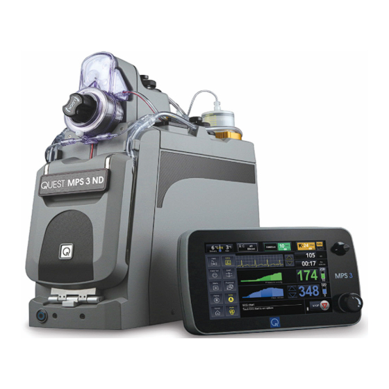
Page 13: System Overview
The MPS 3 ND System consists of the MPS 3 ND Console, Controller, and Disposables (MPS 3 ND Delivery Set and optional accessories). The primary function of the MPS 3 ND System is to aid the perfusionist in cardioplegia delivery to the patient during Cardiopulmonary Bypass Surgery. - Page 14 MPS 3 ND System – System Overview (Under mount) Figure 1: MPS 3 ND Console Overview Item Name Function MPS 3 ND Console Push Button Switch Sleep (OFF) / Wake (ON) MPS 3 Door Contain Blood/Crystalloid Cassette Heat Exchanger (HEX) Locking Knob...
- Page 15 MPS 3 ND System – System Overview Figure 2: MPS 3 ND Console Rear Panel Item Name Function Water Outlet Port Water Outlet to Cold Water Source Water Inlet Port Water Inlet from Cold Water Source Cooling Fans (2X) Maintain Internal Temperature...
-
Page 16: Mps 3 Controller
MPS 3 Controller. The MPS 3 Controller interfaces with the MPS 3 ND Console through the Console to Controller Communicable Cable attached on the back of both modules. - Page 17 MPS 3 ND System – System Overview Figure 3: MPS 3 Controller Overview Item Name Function MPS 3 Controller Touchscreen Display Monitor / Select / Set Parameters Set Knob Scroll Through Parameters USB Port Connect USB Drive Flow Control Knob Start / Stop Cardioplegia Delivery 904596 REV F –...
- Page 18 MPS 3 ND System – System Overview Figure 4: MPS 3 Controller Rear Panel Item Name Function Type A USB Port Expansion Port Type B USB Port Service Connection or Electronic Data Management System Communication Cable Port Connect Console to Controller Communication Cable...
-
Page 19: Mps 3 Nd Disposables
The MPS 3 ND Disposables (Delivery Sets and optional accessories) are designed to work in conjunction with the MPS 3 ND Console. The MPS 3 ND Delivery Sets are sterile, single use disposables which consist of a blood / crystalloid cassette, heat exchanger, blood / crystalloid source lines, delivery extension line, and appropriate tubing and luer fittings to complete the cardioplegia circuit. - Page 20 MPS 3 ND System – System Overview Figure 5: MPS 3 ND Delivery Set Item Name Function MPS 3 ND Delivery Set Blood / Crystalloid Cassette Ratio Blood / Crystalloid and pump to HEX Additive Cartridge Deliver Additive Additive Delivery Line...
-
Page 21: System Specifications And Performance
MPS 3 ND System – System Specifications and Performance 3 System Specifications and Performance Console Specifications MPS 3 ND Console Classification of Installation Stationary Mode of Operation Continuous Ingress Protection Marking IPX1 AC Mains Supply Voltage 100-240 V Frequency 50/60 HZ... - Page 22 MPS 3 ND System – System Specifications and Performance MPS 3 ND Console Flow Rate: 5% or 5 ml/min (whichever is greater) Cardioplegia Delivered: 5% or 10 ml (whichever is greater) Accuracy Drug Volume Delivered: ±1 ml or 5% (whichever is greater)
-
Page 23: Controller Specifications
MPS 3 ND System – System Specifications and Performance Controller Specifications MPS 3 Controller Width: 12.5" Dimensions Depth: 4.5" Height: 7.5" Weight 10 lbs. DC Supply Voltage 24 VDC • Isolated USB Host port – 2 Ports (USB memory device access) •... -
Page 24: Mps 3 Nd Disposables Specifications
MPS 3 ND System – System Specifications and Performance MPS 3 ND Disposables Specifications Blood Low Volume Blood Extension Normal Mode Part Number Source Mode Source Line Priming Line Priming Line ID Length Volume Length Volume Delivery Sets with 16 Core Heat Exchangers 1/4”... -
Page 25: Glossary Of Symbols And Labels
MPS 3 ND System – System Specifications and Performance Glossary of Symbols and Labels Console and Controller Symbols and Markings Symbol Description Antegrade External Pressure Transducer Cable Connection ANTEGRADE Port Retrograde External Pressure Transducer Cable Connection RETROGRADE Port Medical Air... - Page 26 MPS 3 ND System – System Specifications and Performance Symbol Description Type CF (“Cardiac Floating”) applied parts that may come in direct contact with the heart. The Minimum Temperature Limit. The Maximum Temperature Limit. The acceptable Upper and Lower Limits of relative humidity for transport and storage.
-
Page 27: Delivery Set And Optional Accessories Symbols And Markings
MPS 3 ND System – System Specifications and Performance Delivery Set and Optional Accessories Symbols and Markings Symbol Description Accompanying documents shall be consulted before use of equipment or accessories Do not use if package is damaged Do not resterilize... - Page 28 MPS 3 ND System – System Specifications and Performance This page intentionally left blank Quest Medical, Inc. 904596 REV F – 01/2024...
-
Page 29: Warnings And Cautions
USE ONLY QUEST MEDICAL AUTHORIZED SERVICE TECHNICIANS. Quest Medical, • Inc. cannot assure safe operation of the MPS 3 ND System if it is serviced by anyone other than an authorized service technician. Unauthorized service voids all warranties. Use of the device is restricted to professionally trained personnel in accordance with the •... - Page 30 • Ensure use of MPS 3 ND System only with proper functioning equipment in the OR. Use of malfunctioning equipment could be a potential fire hazard. Water quality in the MPS 3 ND System must be maintained per the recommendations in •...
-
Page 31: Installation And Setup Cautions
Portable RF communications equipment (including peripherals such as antenna cables and external antennas) should be used no closer than 30 cm (12 inches) to any part of the MPS 3 ND System, including cables specified by the manufacturer. Otherwise, degradation of the performance of this equipment could result. - Page 32 Increase the separation distance between the receiving device and the MPS 3 ND System. o Connect the MPS 3 ND System into an outlet on a separate circuit from the receiving instrument(s). o If the above actions do not correct the problem, call the Quest Medical Service Department for advice on additional remedies.
-
Page 33: System Warnings And Cautions
MPS 3 ND System is exhibiting electrical malfunctions. • Observe all alarm codes and messages. Do not use the MPS 3 ND System in the event of a non-recoverable (fatal) error message. Contact Quest Medical Customer Service. - Page 34 Use the Quest provided USB memory device solely for the MPS 3 Controller. DO NOT USE this USB memory device in devices or computers not approved for use with the MPS 3 ND System. Add the Quest supplied USB memory device to your organization’s IT security program.
-
Page 35: Disposable Circuit Priming And Delivery Cautions
DO NOT LOAD cassette/cartridges if the pistons are in the forward position. Cycle the power to reset the pistons. If the pistons do not retract, STOP THE MPS 3 ND System and call Quest Medical Technical Support. If the pump piston is not fully retracted, there may be an unintentional bolus delivery during the onset flow. -
Page 36: Priming
Biological contamination is a risk after more than 12 hours. • Close the door before using the MPS 3 ND System. The door must be closed to operate the MPS 3 ND System. However, DO NOT USE force to open or close the doors. Forcing a door closed may indicate an improperly installed or overfilled disposable. -
Page 37: Cardioplegia Delivery
(safe state). • The operator is responsible for maintaining safe operating flow rates. The ECG connection on the MPS 3 ND System is only an activity monitor • and is NOT A MAIN MONITORING DEVICE. Any decisions in care should be made by a main monitor and not the MPS 3 ND System display. -
Page 38: System Cleaning
DO NOT immerse unit in any kind of ultrasonic bath, disinfectant, cleaning solution, • or any kind of liquid. Do not spray liquids directly onto the MPS 3 ND System and prevent liquids from entering the Console and Controller as this may short-circuit the internal electronics and can cause potential hazard for operator and/or patient. -
Page 39: System Installation
Each MPS 3 ND System goes through a rigorous final inspection program prior to its shipment to the customer. Upon the arrival of the MPS 3 ND System, please visually inspect the outside of the shipping container for any damage. If damage is detected, please notify Quest Medical customer service and file a damage claim with the carrier. -
Page 40: Unpacking The Mps 3 Nd System
If the accessories are visibly damaged, DO NOT unpack the components. Contact Quest Medical Customer Service. 4. Remove the top layers of foam packaging to uncover the MPS 3 ND inner box. 5. With the help of an assistant, remove the inner box from the shipping box by lifting it from the handles on the side of the inner box. -
Page 41: Unpacking The Mps 3 Nd Console
Contact Quest Medical Technical Support. 8. Use care when transporting your MPS 3 ND System to its point of use. Unpacking the MPS 3 ND Console ollow these steps to unpack the MPS 3 ND Console: 1. -
Page 42: System Components
MPS 3 ND System – System Installation System Components The following components are required for installation and initial system setup. Component P/N Description Reference Image MPS 3 ND Console 5301000ND 100 – 120V, 50/60 Hz MPS 3 Controller 5303000 MPS 3 Console to Controller... -
Page 43: System Accessories
MPS 3 ND System – System Installation System Accessories Component P/N Description Reference Image 5303030 MPS 3 ND Hose Connector Kit 5001110 MPS Water Circuit Adapter 5303010-(XX) MPS 3 Medical Air Hose Kit 5301023 MPS 3 Console Pole Mount 5301025... - Page 44 MPS 3 ND System – System Installation Component P/N Description Reference Image 513UEXT MPS 3 ECG Extension Cable 513USPT MPS 3 ECG Splitter MPS 3 Antegrade (Aortic Root) 511800A Transducer Interface Cable MPS 3 Retrograde (Coronary 511800R Sinus) Transducer Interface...
-
Page 45: Installing The Mps 3 Nd System
(HLM) for delivery of cardioplegia solution to the patient. This can be accomplished by mounting the MPS 3 ND Console on the base of the HLM or on a Quest Medical supplied MPS 3 ND Console Pole Mount. The MPS 3 ND Console should be placed in a location that is convenient for safe and effective operation. - Page 46 MPS 3 ND System – System Installation For installation of the MPS 3 ND Console on the HLM Base, follow these steps: 1. Consult the HLM Operation Instructions prior to attempting to install the MPS 3 ND Console to ensure the console can be safely installed.
- Page 47 MPS 3 ND System – System Installation 6. Connect the Power Cord to the AC Connector on the back of the MPS 3 ND Console. The Power Cord should be inserted through the Strain Relief Clamp by unscrewing the clamp and running the power cord through the clamp.
- Page 48 MPS 3 ND System – System Installation For installation of the MPS 3 ND Console on the HLM Pole, follow these steps: 1. Consult the HLM Operation Instructions prior to attempting to install the MPS 3 ND Console to ensure the console can be safely installed.
- Page 49 MPS 3 ND System – System Installation 6. Lift the MPS 3 ND Console using the handles located under the front of the Console and at the top of the back panel. If necessary, seek assistance when lifting the MPS 3 ND Console.
- Page 50 MPS 3 ND System – System Installation 9. Connect the Power Cord to the AC Connector on the back of the MPS 3 ND Console. The Power Cord should be inserted through the Strain Relief clamp by unscrewing the clamp and running the power cord through the clamp.
-
Page 51: Installing The Mps 3 Controller
MPS 3 ND System – System Installation Installing the MPS 3 Controller The MPS 3 Controller should be placed in a location that is easily accessible and visible for the operator. The location should also allow for minor adjustments to the Controller position to accommodate viewing angles and reach for all operators who may operate the device. - Page 52 MPS 3 ND System – System Installation 5.5.2.1 To install the MPS 3 Controller using the Telescoping Mounting Arm (P/N 5303008) on the HLM Pole, follow these steps: 1. Consult the HLM Operation Instructions prior to attempting to install the MPS 3 Controller to ensure the Controller can be safely installed.
- Page 53 MPS 3 ND System – System Installation Telescoping Mounting Arm. Carefully slide the Controller onto the Pole Mounting Arm. The quick release adapter should click into place when properly secure. The quick release lever should be positioned vertically after the Controller is secured to Telescoping Mounting Arm.
- Page 54 MPS 3 ND System – System Installation 7. The Pole Mounting Arm length can be adjusted by lifting the telescoping clamp and extending the arm to the desired length. If the telescoping clamp needs to be tightened or loosed, simply adjust the hex nut on the mechanism with a 3/16”...
- Page 55 MPS 3 ND System – System Installation 5.5.2.2 To install the MPS 3 Controller using the Articulating Mounting Arm (P/N 5303007) on the HLM Pole, follow these steps: 1. Consult the HLM Operation Instructions prior to attempting to install the MPS 3 Controller to ensure the Controller can be safely installed.
- Page 56 MPS 3 ND System – System Installation 4. Position the pole clamp over the vertical pole and tighten the pole clamp by turning the handle clockwise. Tighten the pole clamp hand tight so that it is secure, but not overtightened. Test the securement of the pole clamp to the pole prior to installing the MPS 3 Controller.
- Page 57 MPS 3 ND System – System Installation 7. Once installed, the MPS 3 Controller viewing angle can be adjusted by first unscrewing the “lock” on the controller tilt head closest to the mounting plate until just loose enough. Then, grab both sides of the Controller and adjust.
-
Page 58: Connecting A Heater-Cooler Unit To The Mps 3 Nd System
Connecting a Heater-Cooler Unit to the MPS 3 ND System The Heater-Cooler Unit (HCU) must supply an adequate water flow rate (greater than 1.25 gpm) and water temperatures (0 – 41°C) for the MPS 3 ND System to operate properly. - Page 59 MPS 3 ND System – System Installation Please follow these steps to connect the HCU to the MPS 3 ND System. 1. Consult the HCU Operation Instructions / User Manual prior to attempting to connect the HCU to the MPS 3 ND System the HCU will supply adequate water flow and water temperatures.
- Page 60 4. Because the water circuit is now part of the delivery set, refer to Section 8.1 to install the delivery set prior to making the water connections. 5. Connect the Quick Disconnect fittings to the MPS 3 ND Console water inlet and outlet ports that have presented out of the back of the console.
-
Page 61: Priming The Water Circuit
MPS 3 ND System – System Installation Priming the Water Circuit The MPS 3 ND System water circuit must be fully primed and purged of all air prior to use to ensure full functionality of the system. Failure to do may result in loss of temperature regulation of cardioplegia solutions. -
Page 62: Installing The Optional Accessories
The following accessories are considered optional for use with the MPS 3 ND System and are not required for initial installation and setup. These accessories are provided to enhance the experience with the MPS 3 ND System and accommodate a variety of needs for various operators. - Page 63 MPS 3 ND System – System Installation To connect the Medical Air Supply to the MPS 3 ND System, please follow the following steps. 1. Verify that the Medical Air Supply has a pressure not exceeding 55 psi. High pressures may damage the MPS 3 ND System.
-
Page 64: Connecting To The Electronic Data Management System (Edms)
3 ND System. Ensure that all fingers are free from pinch / crush hazards while connecting the EDMS Cable. To connect the EDMS Cable to the MPS 3 ND System, please follow the following steps. 1. Verify that the EDMS is compatible with the MPS 3 ND System. -
Page 65: Connecting The Electrocardiogram (Ecg) Cable
1. Verify that the ECG is compatible with the MPS 3 ND System. The ECG port of the MPS 3 ND System is designed to be used with a ¼” Phono ECG cable. 2. Verify that the ECG Cable provided has the correct connections for your ECG system. -
Page 66: Connecting The External Antegrade And Retrograde Pressure Cables
MPS 3 Controller display. The sterile, single use Pressure Transducers can be purchased as optional disposable accessories. This section will detail how to connect the reusable Pressure Cables to the MPS 3 ND System for use with the disposable Pressure Transducers. - Page 67 3 ND System, please follow the following steps. 1. Connect the External Antegrade Pressure Cable to the rear panel of the MPS 3 ND Console in the Antegrade Pressure Connector. The Antegrade Pressure Cable and Pressure Connector are color coded red to help guide proper connections.
- Page 68 MPS 3 ND System – System Installation This page intentionally left blank 5-30 Quest Medical, Inc. 904596 REV F – 01/2024...
-
Page 69: Mps 3 Nd Startup
This section contains the steps to power on the MPS 3 ND System. Prior to attempting to power on the MPS 3 ND System for the first time, please ensure all steps outlined in Section 5 were followed closely and with the help of authorized Quest Medical personnel, an authorized representative of Quest Medical, or a trained technician. - Page 70 To power on the MPS 3 ND System, follow the steps outlined below: 1. Turn main power switch on the rear panel of the MPS 3 ND Console to the ON position. The push button switch on the front of the MPS 3 ND Console will be illuminated in orange to verify the main power switch is in the ON position.
- Page 71 3. After the system is powered on, the MPS 3 Controller will display the startup screen. The startup screen will indicate the MPS 3 ND System is powered on and System Diagnostics is being performed. Alarm messages will be displayed on the startup screen should an error be encountered during System Diagnostics.
- Page 72 MPS 3 ND System – Startup 4. Once System Diagnostics has completed successfully, the selection screen will illuminate the following options: RESUME CASE (Section 9.2) • NEW CASE (Section 9.1) • • PROTOCOL MANAGER (Section 9.3) MENU (Section 9.4) •...
-
Page 73: System Settings
MPS 3 ND System – Startup System Settings When the MPS 3 ND System is powered on for the first time, it is recommended that the operator adjust the System Settings to the desired preference. The following parameters may be changed in the Settings menu. - Page 74 MPS 3 ND System – Startup 2. The settings menu is displayed on 3 pages. To cycle through pages, use the arrow buttons near the page numbers. Figure 32: Settings Menu, Page 1 3. To change Delivery Line Type, select the selection button and choose single or double.
- Page 75 MPS 3 ND System – Startup 7. Once the settings on page 1 are configured, select the right arrow to move to page 2 of the Settings menu. Figure 33: Settings Menu, Page 2 8. To select Language, select the selection button and choose the desired language.
- Page 76 MPS 3 ND System – Startup 12. To set the Date, select the selection button and enter the date using the arrow keys. 13. To set the Time, select the selection button and enter the time using the arrow keys.
-
Page 77: Graphical User Interface (Gui) Overview
MPS 3 ND System – Graphical User Interface (GUI) Overview 7 Graphical User Interface (GUI) Overview The MPS 3 Controller utilizes a Graphical User Interface (GUI) to allow the operator to set parameters, start / stop cardioplegia delivery, and monitor delivery parameters. The interface is intuitive in operation, but this section will detail the layout of the interface for further clarification. - Page 78 MPS 3 ND System – Graphical User Interface (GUI) Overview Icon Name Description The Flow Rate (1) displays the current flow rate. A Flow Rate and dynamic vertical flow bar displays the flow range and Range dynamically represents the current flow rate value with respect to the flow limits.
- Page 79 MPS 3 ND System – Graphical User Interface (GUI) Overview Icon Name Description The Delivery Temperature (11) displays the delivery Delivery temperature in °C. Temperature The ECG (12) button displays the waveform of the ECG signal received from the analog ECG port.
- Page 80 MPS 3 ND System – Graphical User Interface (GUI) Overview Icon Name Description The VTBD and TTBD (23) counters count down the VTBD / TTBD volume or time during delivery. Flow is automatically Counter stopped when the counter reaches 0.
-
Page 81: Home Screen Views
MPS 3 ND System – Graphical User Interface (GUI) Overview Home Screen Views The Home screen provides the operator with the buttons and views that allows the operator the flexibility to view and modify the parameters while delivering Cardioplegia to the patient. These parameters can be set and monitored by the operator at any time during the case. - Page 82 MPS 3 ND System – Graphical User Interface (GUI) Overview Home View – Flow, Pressure, Time, and Volume are displayed in an enlarged • view Figure 37: Home View Quest Medical, Inc. 904596 REV F – 01/2024...
-
Page 83: Changing Case Parameters During Delivery
2. The Low Vol button is only active if the current flow rate is 0 ml/min. Selecting the Low Vol button will put the MPS 3 ND System in a flow mode where it pumps with a reduced stroke volume. The maximum flow rate is limited to 200 ml/min. -
Page 84: Delivery Pressure Settings
MPS 3 ND System – Graphical User Interface (GUI) Overview to select the Auto-Start button which causes the flow to ramp up until the Target pressure is reached. Auto-Start is disabled for Ante-External Pressure, Retro, Simulgrade, and Graft mode. Delivery Pressure Settings The System pressure is always displayed. - Page 85 MPS 3 ND System – Graphical User Interface (GUI) Overview Figure 40: Ante Pressure Settings Figure 41: Retro Pressure Settings 904596 REV F – 01/2024 Quest Medical, Inc.
- Page 86 MPS 3 ND System – Graphical User Interface (GUI) Overview Figure 42: Graft Pressure Settings 3. The following table summarizes the pressure limits for Antegrade, Retrograde, and Graft Only modes. All are settable in increments of 1. The lower pressure limit maximum will be limited to 20 mmHg less than the current upper pressure limit setting.
-
Page 87: Time
MPS 3 ND System – Graphical User Interface (GUI) Overview Time The Time displays the On / Off time for the pump. The ‘On Time’ displays when the dose is delivering and ‘Off Time’ is displayed when not delivering. The Stopwatch Timer will be displayed in the ‘On Time’... - Page 88 MPS 3 ND System – Graphical User Interface (GUI) Overview Ischemic Timer 7.3.3.1 The Ischemic Timer gives the operator the ability to be notified when a set period of non-delivery has elapsed. This notification is provided by an audible tone and by flashing the timer display. There are two different timers that can be set: the Initial Timer and the Repeat Timer.
-
Page 89: Volume
MPS 3 ND System – Graphical User Interface (GUI) Overview Volume The Incremental Volume displays the total Cardioplegia volume (blood + crystalloid + arrest + additive) delivered during the current ‘On’ Time. When flow is stopped, the Incremental Volume display shall continue showing the incremental volume. - Page 90 MPS 3 ND System – Graphical User Interface (GUI) Overview 4. Set the VTBD and TTBD values. Button VTBD TTBD Delivers the set volume for a Delivers for the set duration Time single dose for a single dose Delivers for the set duration...
- Page 91 MPS 3 ND System – Graphical User Interface (GUI) Overview Volume Summary / Delivery Summary 7.3.4.2 The Total, Blood, Crystalloid, Arrest, Additive, Antegrade, Retrograde, Simulgrade, and Graft Only volume counters shall be tracked and dynamically displayed to the operator. Use the Reset Volumes button to reset all the counters to zero.
- Page 92 MPS 3 ND System – Graphical User Interface (GUI) Overview The Delivery Summary button is used to display the summary of all delivered components to the patient. First, the total non-blood volume is displayed. This is the sum of Crystalloid + Arrest Agent + Additive Volume delivered.
-
Page 93: Arrest Agent (K+)
MPS 3 ND System – Graphical User Interface (GUI) Overview Arrest Agent (K+) The MPS 3 ND System offers the capability to set two arrest agent delivery concentrations as High K+ and Low K+. The High/Low K+ button allows the operator to change between the two concentrations and also, when highlighted, indicates which concentration is displayed. -
Page 94: Additive
Refill and Purge, refer to Section 8.3. Additive The MPS 3 ND System offers the capability to select the name of the Additive and to set the delivery concentration. The Additive concentration range is between 0 ml/L to 50 ml/L. -
Page 95: Blood : Crystalloid
MPS 3 ND System – Graphical User Interface (GUI) Overview Blood : Crystalloid The MPS 3 ND System offers the capability to deliver blood and crystalloid in various ratios. The available options are: • All crystalloid (Cryst) • Blood : Crystalloid Ratios of 1:9 to 1:1 and 2:1 to 66:1 •... - Page 96 MPS 3 ND System – Graphical User Interface (GUI) Overview 1. To set Blood : Crystalloid settings, select the on the Home Screen. The B:C Settings screen is displayed. Figure 52: B:C Settings Screen Figure 53: Blood : Cryst Ratio Selection 2.
-
Page 97: Temperature
Prime or Recirc processes. Temperature The MPS 3 ND System offers the capability to monitor the temperature of the cardioplegia solution delivered to the patient. The delivery temperature as measured in the heat exchanger is displayed. The MPS 3 ND System offers the ability to set a temperature reminder. -
Page 98: Function Buttons
MPS 3 ND System – Graphical User Interface (GUI) Overview Function Buttons The Operator can select the following function buttons from the Home screen. • Vent • Hold Volume • Graft • • Menu • Protocol Retro • Ante •... -
Page 99: Vent
The MPS 3 ND System opens the vent valve instead of the delivery valve. Any air that is trapped in the heat exchanger bubble trap can now be purged via the vent line. The MPS 3 ND System controls ratios but does not deliver Arrest or Additive drugs in Vent mode. -
Page 100: Ecg
MPS 3 ND System – Graphical User Interface (GUI) Overview To view the ECG trace, connect the Controller to the ECG Monitor using the MPS 3 ECG Cable. Follow your ECG monitor manufacturer’s instructions for connection and configuration. Refer to Section 5.6.3 for connection instructions to the MPS 3 Controller. -
Page 101: Ecg Events
MPS 3 ND System – Graphical User Interface (GUI) Overview ECG Events Selecting the ECG chart displays the ECG Event screen. An ECG cable does not have to be connected to the Controller to enter the ECG Event screen or to record events. - Page 102 MPS 3 ND System – Graphical User Interface (GUI) Overview Figure 58: Hot Shot Detection Confirmation Screen Figure 59: Heart Restart Method Selection Screen Figure 60: Cross Clamp (left), Arrested (center), and Rhythm (right) Buttons 7-26 Quest Medical, Inc. 904596 REV F – 01/2024...
-
Page 103: Hold Volume
MPS 3 ND System – Graphical User Interface (GUI) Overview Hold Volume The Hold Vol button indicates the Hold Volume mode is active / inactive. When activated the Hold Vol icon flashes yellow. The incremental volume stops counting and the Off timer starts counting (even if flow > 0). The Air inline sensor is deactivated. -
Page 104: Graft
MPS 3 ND System – Graphical User Interface (GUI) Overview Graft Select the Graft icon button to activate Graft mode and to display the Graft settings screen. The Route label for the dose will change to ‘Ante+Graft,’ ‘Retro+Graft,’ or ‘Simul+Graft’. -
Page 105: Menu
MPS 3 ND System – Graphical User Interface (GUI) Overview Select the Graft Only button to exit Graft Only Mode and to change the route label and pressure limits to ‘Ante+Graft,’ ‘Retro+Graft,’ or ‘Simul+Graft’. Select the Graft icon button to exit ‘Ante+Graft,’ ‘Retro+Graft,’ ‘Simul+Graft,’ or ‘Graft Only’... -
Page 106: Protocol
MPS 3 ND System – Graphical User Interface (GUI) Overview Protocol The Protocol icon button displays the protocol name, if a protocol aside from Defaults is launched. An asterisk ‘*’ next to the name indicates that one or more parameters have been modified from the original saved Protocol when launched. -
Page 107: Delivery Routes
MPS 3 ND System – Graphical User Interface (GUI) Overview Delivery Routes Cardioplegia can be delivered in the following three delivery valve modes: • Antegrade • Retrograde • Simulgrade The currently active delivery route is shown in yellow: Figure 67: Antegrade (left), Retrograde (center), and Simulgrade (right) Delivery Routes To change delivery routes, pressure limits, and dose route labels from Antegrade to Retrograde, or vice versa, short press the route in grey. -
Page 108: Auto Mode And Auto-Start Mode
The upper flow limit is twice the flow rate value when Auto mode is selected or when target pressure is reached. The MPS 3 ND System exits auto mode when the Auto or Stop button is pressed or the flow is adjusted using the flow knob. -
Page 109: Mps 3 Nd Disposable Installation
MPS 3 ND System – Disposable Installation 8 MPS 3 ND Disposable Installation This section details the instructions for installing the MPS 3 ND Delivery Set and optional accessories for use with the MPS 3 ND System. Only genuine Quest disposable components, including delivery sets and extension lines, can be used with the MPS 3 ND System to ensure the intended system performance and reliability. -
Page 110: Installing The Heat Exchanger
MPS 3 ND System – Disposable Installation Installing the Heat Exchanger 1. Turn the MPS 3 ND Console power switch off and then on to ensure the pump pistons are retracted. Open the door to reveal the pumping chambers. DO NOT LOAD cassette if the pistons are in the forward position (convex). - Page 111 Console. Figure 72: MPS 3 ND Locking Knob Engagement Route the vent line through the vent valve on the MPS 3 ND Console by pressing down on the vent valve manual operation button. Ensure tubing is not overstressed or kinked upon installation.
-
Page 112: Installing The Blood / Crystalloid Cassette
Figure 74: MPS 3 B / C Cassette Loading 2. Route the blood and crystalloid inlet tubes through the tubing clamps located on the MPS 3 ND Console and carefully close the door. Quest Medical, Inc. 904596 REV F – 01/2024... - Page 113 3. The blood source line is connected to the blood inlet tubing. Route the tubing along the top of the MPS 3 ND Console using the tubing clamps on the Console. Blood Source...
-
Page 114: Connecting The Delivery Set To The Extracorporeal Circuit
(see step 9 from section 8.1.2). Figure 76: MPS 3 ND Air in Line Sensor Engagement FULLY INSERT the tubing through the air in line detector for proper MPS 3 ND Console operation. -
Page 115: Installing And Filling The Arrest Agent Cartridge
Installing and Filling the Arrest Agent Cartridge DO NOT USE an arrest agent (potassium chloride) concentration other than 2 mEq/ml. The MPS 3 ND System is designed to operate with an arrest agent concentration of 2 mEq/ml. Using an arrest agent... - Page 116 MPS 3 ND System – Disposable Installation 3. With printing facing to the right, align the two flanges on the Arrest Cartridge with the matching features on the Arrest Pump on the MPS 3 ND Console. Figure 79: Align the Cartridge 4.
- Page 117 MPS 3 ND System – Disposable Installation 5. Connect the yellow stopcock Arrest Cartridge Delivery Line with the non- standard luer fitting to the Arrest cartridge and the check valve fitting to the heat exchanger. Figure 81: Arrest Delivery Line Connections 6.
- Page 118 MPS 3 ND System – Disposable Installation 7. Carefully fill the Arrest cartridge by moving the solution from the filling syringe to the Arrest Cartridge. Figure 83: Cartridge filling 8. For best results, ensure that the Arrest Cartridge is free of air by aspirating with the filling syringe.
-
Page 119: Installing And Filling The Additive Cartridge
MPS 3 ND System – Disposable Installation Installing and Filling the Additive Cartridge DO NOT OVERFILL arrest agent or additive cartridges. The normal maximum cartridge capacity is 75 ml. Overfilling the arrest agent or additive cartridges before or after installation in the console can cause unintentional bolus delivery and possible system malfunction. - Page 120 MPS 3 ND System – Disposable Installation 3. With printing facing to the right, align the two flanges on the Additive Cartridge with the matching features on the Additive Pump on the MPS 3 ND Console. Figure 86: Align the Additive Cartridge 4.
- Page 121 MPS 3 ND System – Disposable Installation 5. Connect the green stopcock Additive Cartridge Delivery Line with the standard luer fitting attaching to the Additive cartridge and the check valve fitting to the heat exchanger. Figure 87: Connect check valve to heat exchanger 6.
-
Page 122: Priming And Recirculation
Prior to delivering cardioplegia, the delivery set must be primed to remove all air in the delivery set and the drug cartridges. After the disposable is loaded, the MPS 3 ND System is powered on, and case parameters have been entered, the MPS 3 ND System is ready to perform the priming sequence. - Page 123 MPS 3 ND System – Disposable Installation To start the Auto Prime sequence, follow the steps outlined below: 1. Select the Prime button on the New Case Setup screen and a start prime screen displays. Figure 89: Prime Screen 2. Select the Start Prime button on the Prime screen, and the Auto Prime sequence will initiate.
- Page 124 During recirculation mode (Recirc) the MPS 3 ND System switches to all blood mode and recirculates the solution through the vent valve to the cardiotomy reservoir. To perform Recirc, set the flow rate by adjusting the flow knob.
- Page 125 No arrest agent or additive is delivered during Recirculation Mode. In Vent mode, the MPS 3 ND System will recirculate by delivering via the Vent valve the selected blood / crystalloid value. (i.e., if 4:1 is selected, 4 parts Blood and 1 part Crystalloid will be delivered).
-
Page 126: Refill Arrest Agent
The purge button will be disabled while refilling the arrest agent. The MPS 3 ND System allows the operator to refill the arrest agent cartridge at any time. To refill the arrest agent: 1. Select icon on the Home screen. -
Page 127: Purging The Arrest Agent Cartridge Line
The purge button will be disabled while refilling the arrest agent. The MPS 3 ND System allows the operator to refill the additive cartridge at any time. To refill the additive cartridge: 1. Select icon on the home screen. -
Page 128: Purging The Additive Cartridge Line
MPS 3 ND System – Disposable Installation The Additive pump is automatically turned Off when the cartridge is empty and the following alarm is displayed: “Additive cartridge is empty Additive pump is Off” When cartridge refilled, pump automatically turned on. -
Page 129: Replacing The Crystalloid Bag
MPS 3 ND System – Disposable Installation 3. Fill the cartridge and then select the ENABLE button on the message window. System initiates the Auto Priming sequence and Home Screen will be displayed when the priming process is completed. Replacing the Crystalloid Bag If crystalloid is being used for cardioplegia delivery, a Crystalloid Volume Remaining must be entered. -
Page 130: Removing The Delivery Set
Removing the Delivery Set Always clamp all input and delivery lines BEFORE OPENING the MPS 3 ND System door. Failure to clamp the lines will result in unrestricted flow (FREE FLOW) of solutions, including drainage from the arterial line of the extracorporeal circuit and possible patient injury. -
Page 131: Mps 3 Nd System Functional Use
MPS 3 ND System – Functional Use 9 MPS 3 ND System Functional Use This section details higher level functionality of the MPS 3 ND System. To power on the MPS 3 ND System refer to Section 6.1. Figure 94: Selection Screen... -
Page 132: Defaults
Confirm All button to accept all the parameters and go directly to the Auto Prime screen. Note that in the MPS 3 ND System, Page 2 of 8 is grayed out during New Case setup since temperature control functionality is inactive. - Page 133 MPS 3 ND System – Functional Use Figure 96: New Case Parameters, Page 1 Figure 97(a): New Case Parameters, Page 2 904596 REV F – 01/2024 Quest Medical, Inc.
- Page 134 MPS 3 ND System – Functional Use Figure 98: New Case Parameters, Page 3 Figure 99: New Case Parameters, Page 4 Quest Medical, Inc. 904596 REV F – 01/2024...
- Page 135 MPS 3 ND System – Functional Use Figure 100: New Case Parameters, Page 5 Figure 101: New Case Parameters, Page 6 904596 REV F – 01/2024 Quest Medical, Inc.
- Page 136 MPS 3 ND System – Functional Use Figure 102: New Case Parameters, Page 7 Figure 103: New Case Setup Parameters Quest Medical, Inc. 904596 REV F – 01/2024...
- Page 137 MPS 3 ND System – Functional Use The following table summarizes the New Case parameters that can be set by the operator during each new case setup. Range Factory Item Parameter Name Description Default Minimum Maximum Value Value Value High arrest agent...
- Page 138 MPS 3 ND System – Functional Use Range Factory Item Parameter Name Description Default Minimum Maximum Value Value Value Pressure source Retro Source External, System System for Retro Retro Ext Retro Ext Upper Pressure upper Limit limit Retro Sys Retro Sys Upper...
- Page 139 MPS 3 ND System – Functional Use Range Factory Item Parameter Name Description Default Minimum Maximum Value Value Value Initial Delivery Antegrade, Retrograde, Initial Del Route Route Setting Antegrade Simulgrade After Prime Delivery Line Del Line Type Single, Double Single...
-
Page 140: Using An Existing Protocol
MPS 3 ND System – Functional Use Using an Existing Protocol New Case Setup Using an Existing Protocol allows the operator to select an existing protocol from a list of previously saved protocols. The saved protocol feature can standardize cardioplegia delivery parameters and shorten set-up time. -
Page 141: Resuming An Existing Case
The Protocol Manager allows the operator to recall and edit an existing protocol or to create a new protocol and store it on the MPS 3 ND System for future use. 1. To create a new protocol. Select the Protocol Manager Button in the Selection screen. - Page 142 MPS 3 ND System – Functional Use 2. To create a new protocol, select the Create New button on the Protocol list screen. The Create From screen displays as shown below: Figure 107: Create Protocol Screen 3. Select an option and the Protocol Name screen displays where the new protocol name may be entered.
- Page 143 MPS 3 ND System – Functional Use 4. Enter the protocol name and select the Done button to save the protocol name. The maximum character length for the protocol name is 14 alpha-numeric characters. All parameters can be reviewed and edited.
-
Page 144: Interfacing With Menu
For details regarding the Settings menu, refer to Section 6.2. H2O Circ H2O Circ contains features and functionality available in the standard MPS 3 System. Those features are inactive on the MPS 3 ND System. The button is greyed out and cannot be selected. 9-14 Quest Medical, Inc. -
Page 145: Device Info
USB memory. Select Menu File Transfer Copy from Master to replace all the Protocols, Additive, Crystalloid, and Personnel data on the MPS 3 ND System with that from the Master File on the inserted USB memory device. - Page 146 Select Menu File Transfer Case History Quest Internal Memory to view the list of all Case Records available on the MPS 3 ND System up to a max of 225 cases. Select cases and use the delete button to delete them. Select 1 case and use the View button to view the Case details.
- Page 147 MPS 3 ND System – Functional Use button to delete them. Select 1 case and use the View button to view the Case details. Copying cases from the external USB memory to the Quest Internal memory is not allowed. Selecting the Delete Patient Data button will delete the Age, BSA, Weight, Patient ID and Gender data stored for all cases in internal device memory.
-
Page 148: Case History
MPS 3 ND System – Functional Use Case History The Case History function allows the operator to view the list of 225 most recent case records. These records are identified by the case start date and time, for example [21 JUN 2020 13:15]. When an external storage device is plugged in, a case record can be copied to the memory. - Page 149 MPS 3 ND System – Functional Use The dose history displays in a table where each row or record corresponds to a dose. If while flowing during a case the operator changes Delivery Route (Ante/Retro/Simul), selects Arrested/ Rhythm/Hotshot, Graft On/Off, Graft Only, or Graft Label, a New Dose is created.
- Page 150 MPS 3 ND System – Functional Use Editing Graft Label 9.4.5.1 To edit the Graft label: 1. Select the Graft Label cell and a Graft label screen displays as shown below: Figure 117: Graft Label Screen 2. The operator may label or re-label a Dose by selecting from two different lists to label the Graft;...
- Page 151 MPS 3 ND System – Functional Use Dose Record View 9.4.5.2 When a dose is selected, the corresponding pressure, flow, and external pressure data is displayed on three separate graphs. A single dose is limited to a maximum of four hours (looped data). The data...
- Page 152 MPS 3 ND System – Functional Use Case Report 9.4.5.3 The Case Report contains all Patient and Procedure details in one place. To view the Case Report: 1. Select Menu Case History Case Case Report. The Case Report screen 1 of 4 is displayed.
- Page 153 MPS 3 ND System – Functional Use Figure 119: Case Report 1 of 4 Figure 120: Case Report: Procedure View 904596 REV F – 01/2024 Quest Medical, Inc. 9-23...
- Page 154 MPS 3 ND System – Functional Use Figure 121: Case Report: Procedure: CABG View The fields in Case Report screen 2 of 4 are explained below. Glucose values in the alternate units are auto populated in the corresponding fields. Cross-Clamp Time (min): This field displays the XClamp Time as recorded in the ECG Setting screen.
- Page 155 MPS 3 ND System – Functional Use Arrest Dose Flow (ml/min): This field displays the average cardioplegia flow during the dose the Arrest button was selected on the ECG Setting screen. Subsequent Arrest Dose Flows are displayed if multiple Arrest Doses are recorded in the ECG Event Screen.
- Page 156 MPS 3 ND System – Functional Use First Glucose IntroOp (mmol/L): Use this field to record the Glucose concentration in mmol/L prior to going on CPB. First Glucose on CPB (mg/dl): Use this field to record the first Glucose concentration in mg/dl while on CPB.
- Page 157 MPS 3 ND System – Functional Use Cell Saver Return Volume (ml): Use this field to record Cell Saver Return Volume. Hemo Concentrator used?: Use this field to record whether a Hemo concentrator was used. Hemo Concentrator Volume (ml): Use this field to record the volume of Hemo concentration.
- Page 158 MPS 3 ND System – Functional Use The fields in Case Report screen 3 of 4 are explained below. TEE Score: Enter the TEE (Transesophageal Echocardiogram) score with range 0 – 9. PRBC: Enter PRBC (Packed Red Blood Cells) given with range 0 – 9 Units.
-
Page 159: Additive List
MPS 3 ND System – Functional Use Additive List The Additive List contains a list of Additives created by the operator. Items in the list can be added, deleted, or edited. To add an item to the Additive list: 1. In Selection Screen, select Menu Additives. The Additive List screen is displayed. - Page 160 MPS 3 ND System – Functional Use 3. All the fields in the Additive Template have to be filled to match the Additive solution being used. The ‘per L cdpg’ (quantity of component delivered per liter of cardioplegia) and ‘Total Volume’ fields are calculated by the MPS 3 ND System based on the provided information.
-
Page 161: Crystalloid List
3. All the fields in the Crystalloid Template have to be filled to match the Crystalloid solution being used. The ‘per L cdpg’ and ‘Crystalloid Volume’ fields are calculated by the MPS 3 ND System based on the provided information. A component can be deleted by selecting the component’s name and then selecting Delete Row. -
Page 162: Component List
MPS 3 ND System – Functional Use Component List The Component List contains a list of up to 6 custom Components created by the operator. The Component List already has 9 reserved Component names (KCL, Mag Sulfate, Lido 1%, Lido 2%, Mannit 20%, Adenosine, NaHCO Mannit 25%, and Insulin). - Page 163 MPS 3 ND System – Functional Use Figure 130: Surgeon List Figure 131: Anesthesiologist List 904596 REV F – 01/2024 Quest Medical, Inc. 9-33...
-
Page 164: Error Report
MPS 3 ND System – Functional Use Figure 132: Perfusionist List Error Report The Error Report menu option lists all the Errors on the device in Chronological order along with time stamp and Error code. This list helps Service personnel to identify and troubleshoot an error condition on your device. -
Page 165: Trainer Mode
Trainer Mode, select Trainer and confirm Yes on the dialogue box. The MPS 3 ND System will restart and an orange border will be displayed around the screen to alert operators they are in Trainer Mode and the Console is no longer responding to commands from the Controller. - Page 166 MPS 3 ND System – Functional Use Figure 135: Trainer Mode 9-36 Quest Medical, Inc. 904596 REV F – 01/2024...
-
Page 167: Shut Down And Restart
MPS 3 ND System – Functional Use Shut Down and Restart To power off the MPS 3 ND System into Standby mode, select Shut Down and confirm Shut Down on the dialogue box. To completely shut down the MPS 3 ND System, turn main power switch on the rear panel of the console to the OFF position. -
Page 168: Data Transfer
Data Logs with time stamps. Data Transfer Data transfer allows the operator to copy the information from MPS 3 ND System to external storage media. The operator is able to copy the information related to: Protocols, Additives, Crystalloids, Components, Personnel •... -
Page 169: 10 Alarm Overview
Alarms and errors are the notifications to the operator to ensure safe and proper function of the MPS 3 ND System. The alarm message states the alarm or error code, a brief description of the alarm, and prompts for clearing the alarm. All Alarms are recorded in the Alarm Report and may be accessed from the Menu option. -
Page 170: Medium Priority Alarms
MPS 3 ND System – Alarm Overview The sound pressure level for the High Priority acoustic alarm tones can be adjusted using the Audio Level Menu setting according to the table below Audio Level = 1 Audio Level = 5... -
Page 171: Informational Tones
MPS 3 ND System – Alarm Overview Informational Tones Informational Tones are used to indicate conditions that do not require any operator acknowledgement. They are announced by a non-repeating audible signal and sometimes visually by flashing a displayed value or symbol such as when pressure or flow limit values exceed the set limit, or the Ischemic timer has expired. - Page 172 MPS 3 ND System – Alarm Overview This page intentionally left blank 10-4 Quest Medical, Inc. 904596 REV F – 01/2024...
-
Page 173: 11 Troubleshooting
The MPS 3 Blood Bypass Tubing (REF 5301016) is only for use as a back-up with an MPS 3 or MPS 3 ND System to continue fluid delivery in the event of complete battery depletion after AC power failure or if the System becomes unusable even after following the corrective action and troubleshooting suggestions in Sections 11.3 and... -
Page 174: Alarm Code List And Solutions
MPS 3 ND System – Troubleshooting Alarm Code List and Solutions The following table lists alarm (error) codes, the displayed message, and recommended corrective action. The alarm code is displayed in the message window. A chronological listing of all alarm codes on the device can be accessed by selecting the Error Report button from the Menu screen. - Page 175 MPS 3 ND System – Troubleshooting Alarm Code Message Display Corrective Action Priority Door Open detected * Open and Close door Close door and press RETEST * Select ignore if operator feels (Press IGNORE only if faulty sensor) door is securely even when...
- Page 176 MPS 3 ND System – Troubleshooting Alarm Code Message Display Corrective Action Priority * Manually actuate delivery and vent valves several times Delivery Valve failed diagnostics * Clean valves if dirty * Restart system High RESTART CONFIRM * Call service after multiple...
- Page 177 MPS 3 ND System – Troubleshooting Alarm Code Message Display Corrective Action Priority System Config mismatch Error 28, 29 * Restart System Call Service * Call service after multiple High occurrences SHUTDOWN RESTART Fluid Level sensor test failure * Continue with case while...
- Page 178 MPS 3 ND System – Troubleshooting Alarm Code Message Display Corrective Action Priority * If there is NOT air present in heat exchanger, check heat exchanger to ensure it is secured tightly with the locking knob & reprime the circuit...
- Page 179 MPS 3 ND System – Troubleshooting Alarm Code Message Display Corrective Action Priority * Check the lines for clamps, kinks, or occlusions * Manually actuate delivery and vent valves several times System pressure sensor error * Check heat exchanger to...
- Page 180 MPS 3 ND System – Troubleshooting Alarm Code Message Display Corrective Action Priority * Check the lines for clamps, kinks, or occlusions * Check the stopcock position at Max external Antegrade pressure the sensor Check circuit * Try to reestablish zero by re-...
- Page 181 MPS 3 ND System – Troubleshooting Alarm Code Message Display Corrective Action Priority * Continue as normal 48, 49 Excessive chamber pressure High CONFIRM * Restart and resume case * Call service after multiple occurrences * Check heat exchanger to...
- Page 182 MPS 3 ND System – Troubleshooting Alarm Code Message Display Corrective Action Priority Air detected in delivery line. Flow continues * Check delivery line to ensure it Manually check for air is fully inserted in sensor * If sensor is ignored, manually...
- Page 183 MPS 3 ND System – Troubleshooting Alarm Code Message Display Corrective Action Priority * Check Crystalloid inlet line for 61, 62 Inadequate Crystalloid fill clamps, kinks, or occlusions Check Source * Raise the Crystalloid bag or CONFIRM Medium use a pressure cuff...
- Page 184 MPS 3 ND System – Troubleshooting Alarm Code Message Display Corrective Action Priority Door is open * Close the door Close door to continue * Select shutdown to turn High System off SHUTDOWN 75, 76 System FPGA Error * Restart System...
- Page 185 MPS 3 ND System – Troubleshooting Alarm Code Message Display Corrective Action Priority Arrest pump failed diagnostics 96, 97, 98 * Restart system Proceed without Arrest pump * Call service after multiple High occurrences RESTART CONFIRM * Choose DISABLE if Arrest...
- Page 186 MPS 3 ND System – Troubleshooting Alarm Code Message Display Corrective Action Priority * Select CONFIRM to turn Arrest pump off and continue procedure Arrest over-delivery detected Arrest has been turned off Medium RETEST CONFIRM * Select RETEST to turn Arrest...
- Page 187 MPS 3 ND System – Troubleshooting Alarm Code Message Display Corrective Action Priority * Check additive delivery line for clamps, kinks, or occlusions * Check stopcock position * If problem persists, replace Additive occlusion during prime additive delivery line and try...
- Page 188 MPS 3 ND System – Troubleshooting Alarm Code Message Display Corrective Action Priority * Check additive delivery line for clamps, kinks, or occlusions * Check cartridge for occlusions/leaks * Check stopcock position Additive under-delivery detected * If problem persists, replace...
- Page 189 MPS 3 ND System – Troubleshooting Alarm Code Message Display Corrective Action Priority Arrest pump is Disabled * Prime arrest pump Medium CONFIRM Additive pump is Disabled * Prime additive pump Medium CONFIRM Delivery temperature sensor error * Manually monitor delivery...
- Page 190 MPS 3 ND System – Troubleshooting Alarm Code Message Display Corrective Action Priority Pneumatic over pressure (> 55 psi) Check medical air source * Disconnect from medical air and retry High SHUTDOWN RETRY Pneumatic leak or internal compressor malfunction * Connect to medical air...
- Page 191 MPS 3 ND System – Troubleshooting Alarm Code Message Display Corrective Action Priority Pneumatic pressure sensor error * Restart System Service required * Call service after multiple High occurrences SHUTDOWN RESTART * Safe to use. Drug pump is fully Drug pump LED fail functional.
- Page 192 MPS 3 ND System – Troubleshooting Alarm Code Message Display Corrective Action Priority Elevated internal temperature detected * Check fans and air inlets for Check for obstructed air flow obstructions Maintenance required * Restart System Medium * Contact service after multiple...
- Page 193 MPS 3 ND System – Troubleshooting Alarm Code Message Display Corrective Action Priority Battery capacity at 25% * Reconnect AC power. If power Reconnect power immediately loss did not occur, check power Medium cord, outlet, or circuit breaker CONFIRM * Reconnect AC power. If power...
- Page 194 MPS 3 ND System – Troubleshooting Alarm Code Message Display Corrective Action Priority System Error * Restart System * Call service after multiple High SHUTDOWN RESTART occurrences * Check the lines for clamps, kinks, or occlusions * Manually actuate delivery and...
- Page 195 MPS 3 ND System – Troubleshooting Alarm Code Message Display Corrective Action Priority Arrest pump Home Sensor fail * Select RETEST Arrest pump is disabled * If error still persists, restart system and try again * Contact service after multiple...
- Page 196 MPS 3 ND System – Troubleshooting Alarm Code Message Display Corrective Action Priority * Select DISABLE to complete Prime Additive pump piston sensor error * Check Additive Cartridge to Verify Arrest cartridge installation verify it is properly installed. * Retry drug Prime from the...
- Page 197 MPS 3 ND System – Troubleshooting Alarm Code Message Display Corrective Action Priority 209, 210, 211, 212, 213, 214, Data Logging Error * Continue as normal Consult Service after this case 215, 216, * Contact service after multiple 217, 218,...
- Page 198 MPS 3 ND System – Troubleshooting Alarm Code Message Display Corrective Action Priority Temperature exceeded allowed limit * Check Heater Cooler Medium * Call service after multiple Check Heater-Cooler occurrences High CONFIRM * Delivery or water temperature Unsafe temperature detected may have exceeded 47°C...
- Page 199 MPS 3 ND System – Troubleshooting Alarm Code Message Display Corrective Action Priority System Error * Restart System * Call service after multiple High SHUTDOWN RESTART occurrences System Communication Error * Manually restart system * Call service after multiple High...
- Page 200 MPS 3 ND System – Troubleshooting Alarm Code Message Display Corrective Action Priority Internal UI temperature Error Check for obstructed air flow * Restart and resume case Unable to proceed. Call for Service * Call service after multiple High occurrences...
- Page 201 MPS 3 ND System – Troubleshooting Alarm Code Message Display Corrective Action Priority Memory Access Failure * Restart system * Call service after multiple High alarms SHUTDOWN RESTART * Continue as normal. Check Protocol File Access Failure Protocols in Protocol Manager...
- Page 202 MPS 3 ND System – Troubleshooting Alarm Code Message Display Corrective Action Priority Master file Unavailable * Master file may be corrupted Please insert media with Master File * Re-download Master File * Call service after multiple Medium CONFIRM occurrences...
- Page 203 MPS 3 ND System – Troubleshooting Alarm Code Message Display Corrective Action Priority Low Additive volume < 10 ml * Refill Additive Medium REFILL CONFIRM Crystalloid source volume low * Stop flow to replace < 150 ml Crystalloid bag and enter new...
- Page 204 MPS 3 ND System – Troubleshooting Alarm Code Message Display Corrective Action Priority * Select DIFF CNTLR if Controller is swapped * Resume Case is disabled Resume case allowed ONLY if Same Controller is present DIFF CNTLR SAME CNTLR High...
-
Page 205: Further Troubleshooting
MPS 3 ND System – Troubleshooting Further Troubleshooting This section describes how to troubleshoot issues that may not be found in the previous table. These tips and guidelines have been developed from operator feedback and experiences. Delivery Line Occlusion/Max Overpressure Alarms Check for any clamps accidentally left on the delivery tubing or kinks •... -
Page 206: System And Internal Error Alarms (Non-Recoverable Alarms)
MPS 3 ND System – Troubleshooting System and Internal Error Alarms (Non-Recoverable Alarms) Constant System and/or Internal Errors alarms are usually an indication • of more serious problems with the instrument. System and Internal Errors are designed to be displayed in instances of •... -
Page 207: Inadequate Fill Alarms/Delay In Delivery
MPS 3 ND System – Troubleshooting Inadequate Fill Alarms/Delay in Delivery If inadequate fill alarms are repeatedly encountered, the source pressures • need to be increased. Increase the blood source pressure or increase the head height and/or utilize a pressure cuff for the crystalloid source. -
Page 208: Console Or Controller Swap Out
MPS 3 ND System – Troubleshooting Console or Controller Swap Out It is recommended to change out the MPS 3 ND Console or MPS 3 Controller only if the MPS 3 ND System becomes unusable after following the corrective actions and troubleshooting suggestions in Sections 11.3 and 11.4. -
Page 209: 12 System Maintenance
MPS 3 ND System – System Maintenance 12 System Maintenance This section details important procedures and practices to maintain the MPS 3 ND System to ensure proper function. Only Quest Medical Service personnel or trained technicians and operators should attempt to perform maintenance on the MPS 3 ND System. -
Page 210: Mps 3 Nd Surface Cleaning And Disinfection
MPS 3 ND System – System Maintenance MPS 3 ND Surface Cleaning and Disinfection As with all equipment in the operating room, the MPS 3 ND System external surfaces should be cleaned and disinfected periodically. Always wipe off spills (blood, crystalloid, etc.) immediately. Delays may create conditions for microbial growth or damage the device. - Page 211 MPS 3 ND System until all surfaces are clean from stains, liquid, and dust. 7. Spray CaviCide® on to the external surfaces of the MPS 3 ND System. Ensure to pay attention to areas which are difficult to access.
-
Page 212: Delivery And Vent Valve Cleaning
MPS 3 ND System – System Maintenance Delivery and Vent Valve Cleaning The MPS 3 ND Console Delivery and Vent Valves consist of a mechanism to open and close the valves during normal operation. This mechanism is designed to last for years, but it must be free from debris and buildup to function properly. -
Page 213: Water Circuit Care
Clean the case, Power / Data cable, and mounting arm with an Antimicrobial wipes. Storage Instructions The MPS 3 ND Console that is not in use should be properly cleaned and stored in a cool, dry location protected from freezing temperatures, see 3.1 Storage Environment. -
Page 214: Preventative Maintenance
Preventative Maintenance (PM) is performed annually at a time at the discretion of Quest. MPS 3 ND Consoles requiring PM that are no longer under warranty are serviced for a cost. Consoles can be returned to Quest for PM or PM serviced in the field. -
Page 215: System Service
MPS 3 ND System – System Maintenance System Service To access the MPS 3 ND System Service Menu, follow the steps outlined below. The MPS 3 ND System Service Menu is only assessable to authorized Quest Medical trained hospital employed... - Page 216 MPS 3 ND System – System Maintenance 3. Select the Data Logs button to view a list of all the log files identified by Case start time, that are available in the system. The operator can select just one or last 10 or last 20 or last 30 or all of the available logs;...
- Page 217 5. Select System Maintenance to view the maintenance screen. The next scheduled Maintenance due date is displayed. Operator is able to change the maintenance due date for the MPS 3 ND System. 904596 REV F – 01/2024 Quest Medical, Inc.
- Page 218 MPS 3 ND System – System Maintenance Figure 146: Maintenance Screen 12-10 Quest Medical, Inc. 904596 REV F – 01/2024...
-
Page 219: 13 Service
13 Service Warranty Service Quest Medical, Inc. warrants its MPS 3 ND System to be free of any defect in material or workmanship for a period of one (1) year from the date of purchase. Any MPS System that, upon receipt and examination by Quest Medical or its authorized agent is found to be defective, will be replaced or repaired at Quest Medical’s sole discretion, without charge, as long as this warranty... -
Page 220: Unscheduled Services
MPS 3 ND Systems requiring service that are no longer under warranty are serviced for a cost. Consoles can be returned to Quest for service or serviced in the field. Prior to any service that may be performed a determination of the problem must be provided to Quest Service personnel to determine if the problem is field or factory repairable. -
Page 221: 14 Part Numbers And Accessories List
MPS 3 ND System – Part Numbers and Accessories 14 Part Numbers and Accessories List Accessories List SKU Part Number REF Description 5301016 MPS 3 Blood Bypass Tubing 5303030 MPS 3 ND Water Hose Connector Kit 513PWCC10 MPS 3 Console to Controller Communication Cable... -
Page 222: Mps 3 Nd Delivery Sets
MPS 3 ND System – Part Numbers and Accessories MPS 3 ND Delivery Sets MPS 3 ND Delivery Sets with 10 Convolution Heat Exchanger Drug Part Number Blood Source Blood Source Extension Line Cartridges Line ID Line Length Length Included 3/16”... -
Page 223: Mps 3 Nd Disposables Optional Accessories
MPS 3 ND System – Part Numbers and Accessories MPS 3 ND Disposables Optional Accessories Part Number Description 5003104 Arrest Agent Cartridge 5003105 Additive Cartridge 5053106 Arrest Agent Delivery Line 5053107 Additive Delivery Line 5001106 3/16” x 10 ft. (120”) Extension Line... - Page 224 MPS 3 ND System – Part Numbers and Accessories This page intentionally left blank 14-4 Quest Medical, Inc. 904596 REV F – 01/2024...
-
Page 225: 15 Appendix
AUTHORIZED SERVICE TECHNICIANS. Quest Medical, Inc. cannot assure safe operation of the MPS 3 ND Console if it is serviced by anyone other than an authorized service technician. Unauthorized service voids all warranties. The MPS 3 ND System should not be used adjacent to or stacked with unapproved electrical equipment. -
Page 226: Electromagnetic Emission
When the MPS 3 ND System is used adjacent to or in close proximity to other equipment the operator should be attentive to unexpected device behavior which may be caused by such radiation. The MPS 3 ND System is intended for use in the electromagnetic environment specified in the tables below. -
Page 227: Electromagnetic Immunity
MPS 3 ND System – Appendix Electromagnetic Immunity Guidance and Manufacturer’s Declaration – Electromagnetic Immunity These devices are intended for use in the electromagnetic environment specified below. The customer or the operator of the device should assure that the device is used in such an environment. - Page 228 MPS 3 ND System – Appendix Guidance and Manufacturer’s Declaration – Electromagnetic Immunity These devices are intended for use in the electromagnetic environment specified below. The customer or the operator of the device should assure that the device is used in such an environment.
- Page 229 0% UT; 70% (50/60Hz) supply powered from an uninterruptible according to power supply or a battery. MPS 3 ND IEC 61000- System is equipped with backup 250/300 Cycles 4-11 battery. 0% UT; 0% (50/60Hz) (5s) Note 1: At 80 MHz and 800 MHz, the higher frequency range applies.
- Page 230 RF transmitters, an electromagnetic site survey should be considered. If the measured field strength in the location in which the MPS 3 ND System are used exceeds the applicable RF compliance level above, the MPS 3 ND System should be observed to verify normal operation.
-
Page 231: Recommended Separation Distance
Recommended Separation Distance Guidance and Manufacturer’s Declaration – Recommended Separation Distance The MPS 3 ND System is intended for use in an environment in which radiated RF disturbances are controlled. The customer or the operator of the device can help prevent... - Page 232 MPS 3 ND System – Appendix The following reference summarize the immunity to RF wireless communication equipment for the MPS 3 ND System Table 1: Enclosure Port Immunity to RF Wireless Communication Equipment Reference 15-8 Quest Medical, Inc. 904596 REV F – 01/2024...
-
Page 233: Mps 3 Aortic Root And Coronary Sinus Transducer Interface Cable
MPS 3 ND Console. INDICATION FOR USE: The transducer interface cable is indicated to be used as the electronic interface between the MPS 3 ND Console and a disposable pressure transducer for purpose of monitoring a defined pressure. CONTRAINDICATION: This product is designed and warranted for use with the MPS 3 Cardioplegia Delivery System only. -
Page 234: Mps ® 3 Bypass Tubing Instructions For Use
MPS 3 ND System – Appendix ® 3 Bypass Tubing Instructions for Use 5301016 3 Blood Bypass Tubing ® Description and connect Blood Bypass Tubing onto left port of 10 The MPS ® 3 Blood Bypass Tubing contains the following convolution heat exchanger.