Table of Contents
Advertisement
Quick Links
NSR-90AHDDVR
Operating Instructions
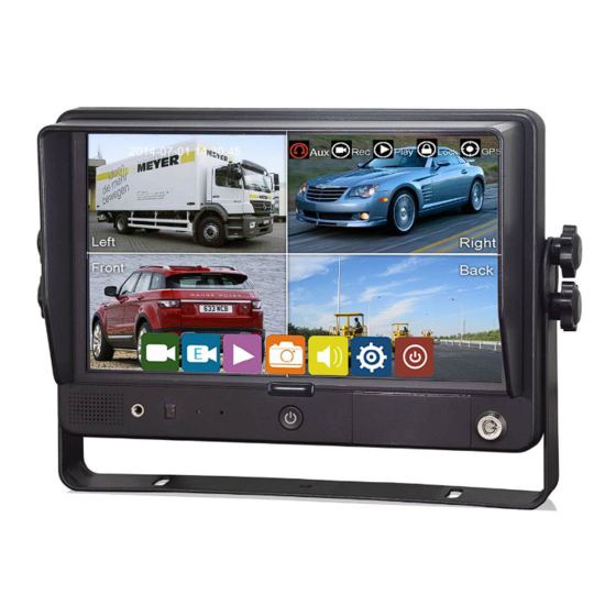
9" HD Digital LCD Color Monitor with 4 Channel Recorder
Please read all instructions before using the product and keep the manual for future reference.
The product may differ from the manual description according to the upgraded.
S/W version or performance, and it may be altered without notice.
V1.1
Advertisement
Table of Contents

Related Manuals for Neltronics NSR-90AHDDVR

Summary of Contents for Neltronics NSR-90AHDDVR
- Page 1 NSR-90AHDDVR Operating Instructions 9" HD Digital LCD Color Monitor with 4 Channel Recorder Please read all instructions before using the product and keep the manual for future reference. The product may differ from the manual description according to the upgraded.
-
Page 2: Table Of Contents
Contents 1. Precautions ..................1 2. Features and Specifications ..............3 3. Accessories ..................4 4. Parts Identification ................5 5. Connections ..................6 6. Menu Operation .................. 7 6.1 IR Remote Control ............... 7 6.2 Touch Screen Function ..............8 7. - Page 3 8.10 Record Audio ................25 9. Display ....................25 9.1 Camera Display Setting ............. 25 9.2 Camera Name Setting ............... 26 9.3 System Language Setting ............27 9.4 Audio Out ................... 27 9.5 OSD Display ................28 9.6 Menu on ..................28 9.7 Speed ..................
-
Page 4: Precautions
1. Precautions ● Storage and Keeping Do not expose the monitor to excessive heat or coldness. Storage temperature is -30~+80℃; Operating temperature is -20~+60℃; Humidity is Rh90%. Never use this device near a bathtub, wash basin, kitchen, damp basement, swimming pool or similar places. - Page 5 ● Maintenance Remove all the cable connections from the monitor before cleaning the device. Use a mild household detergent and clean the unit with a slightly damp, soft cloth. Never use strong solvents such as thinner or benzine, as they might damage the finish of the device.
-
Page 6: Features And Specifications
2. Features and Specifications 9’’ HD quad-view monitor, and resolution is 1024 x 600. Support 4 HD camera inputs and split-view display mode. Multiple video formats available: 1080P30/1080P25/720P30/720P25/PAL/NTSC. Many display modes available. Each channel supports independent image adjustment for horizontal-mirror, vertical-mirror view display. -
Page 7: Accessories
3. Accessories U-Support Bracket Center Mount Bracket Sun Shield IR Remote Control Angle Adjustment Screws Power Cable Special Notice Accessory supply may be different for different application. -
Page 8: Parts Identification
4. Parts Identification ① Remote Receiver. ⑥ Micro SD Slot. ② LDR. ⑦ Insert Direction. ③ Reserved now. ⑧ Slot Number. ④ Power Key. ⑨ Sketch of slots & micro SD card direction. ⑤ Lock. -
Page 9: Connections
5. Connections (A) Black 5P:USB Output, along with USB to CVBS conversion cable for CVBS output. (B) White 4P male for Camera 1. (C) Blue 4P male for Camera 2. (D) Green 4P male for Camera 3. (E) Brown 4P male for Camera 4. ①... -
Page 10: Menu Operation
6. Menu Operation 6.1 IR Remote Control Mute or unmute. Enter/exit the standby mode. Move up the menu cursor. Move right the menu cursor or increase volume. Move left the menu cursor or decrease volume. Call the main menu or return previous page. -
Page 11: Touch Screen Function
● MODE: Call Mode Menu on desktop. ● LANG: Switch to different languages on desktop. ● SEL.: Select item. 6.2 Touch Screen Function When the display shows a split mode and hides the menu, double clicking on one channel will switch to the single screen of that channel. - Page 12 ① System time. ② Mute icon (appears when device is muted). ③ Record icon. ④ GPS signal icon: flickering when connecting, long lit when connected. ⑤ WLAN icon. ⑥ License plate number. ⑦ Channel name. ⑧ Menu zone: Click to show the menu icon. ⑨...
-
Page 13: Menu Lock
7.2 Menu Lock Two types of menu access: administrator access and guest access User permission list Administrator Guest Username admin guest Default password Only snapshot menu, play menu, display mode menu and volume menu. Menu access Username cannot be changed, but the password can be changed. Guests do not have access to the settings menu, so password changing is not available. - Page 14 When the menu lock status is “on”, we need to enter the username admin and password to access the “Record”, “Play”, “Log”, “Settings”, “Disk” and other menus. Username guest and password will only allow access to the “Play” menu. “Layer switching” and “volume adjustment” are open without the need to input any information.
-
Page 15: Keyboard Instruction
7.3 Keyboard Instruction : Uppercase /lowercase switch. : Exit without saving configuration. : Exit after saving configuration. : Delete input characters. : Switch to numbers. : Switch to english. : Switch to special characters. - Page 16 Character Switching:...
-
Page 17: Snapshot
Uppercase /lowercase switch: 7.4 Snapshot Snapshot button:Click this button or press SEL to snapshot a photo and save the screen image as a JPEG image. 7.5 Manual Recording Record button: Click this button, or select it and then press the SEL button to close or open the recording. -
Page 18: Video Playback/Picture Viewing
7.6 Video Playback/Picture Viewing Video playback button: Click this button, or select it and press the SEL button. The system will enter the recording calendar. The prompt dialog box will display “Unable to record in play-back mode! Continue?”. Press “OK” to proceed. If the date mark in the calendar interface is green, it means there’s video files or pictures saved on that day. - Page 19 ① Select the recording type button. Two recording types: normal and event. Capture Saved image for snapshot. ② Play: Play selected video file. ③ Export: export the selected video file to USB (currently not supported). ④ All: select all files on that page. ⑤...
-
Page 20: Log
: Volume adjust button(Only for the video playback interface). : Click the video playback split mode button to switch the split screen to single screen or single screen to segmentation mode(Only the video playback interface has). Play the previous or the next video / Check the previous or the next picture. : Pause or resume playback(Only for the video playback interface). -
Page 21: Display Mode Switch
7.8 Display Mode Switch Display mode button: Click this button, or select it and press the SEL button to enter display mode switching interface. ① Mode selecting. ② Press this button to set the currently selected mode to the default mode. ③... -
Page 22: Volume
to view the status of the storage device. If no storage device is inserted, a prompt of “No Disk Available” will appear. ① Disk type. ② Disk capacity. All: Total capacity of the storage device. Free: The rest available storage. ... -
Page 23: Record Setting
Function Min. Max. Default Volume 8. Record Setting 8.1 Power-on Recording Power-on recording: If this option is set on, the system will start recording after powering on, and this function is set on by default. -
Page 24: Cyclic Recording
8.2 Cyclic Recording Cyclic recording: If cyclic recording is set on, the new video file will overwrite the previous video files when the disk is full. Otherwise, recording will stop when the disk is full. This function is on by default and will soon overwrite recording files. 8.3 Event Recording Event recording: Types of event recording include acceleration sensor triggered alarms and 1-5 triggered alarms. -
Page 25: Video Quality
8.4 Video Quality Main stream is for video storage, while JPG is for WLAN streaming. Default settings of Main stream and JPG are as follows: Main stream Resolution AUTO none Bitrate AUTO none Framerate 25fps ① Five resolution options available for main stream: 1080P, 720P, D1(PAL), D1(NTSC), AUTO. The higher the resolution, the better the video quality, and the larger the video file. - Page 26 In the “Bitrate” option, “AUTO” is defined as follows: Main stream If a 1080p camera is connected, the bitrate is 4Mbps. Likewise, AUTO 2Mbps for a 720p camera, 1Mbps for a d1 camera. ③ Framerate There are 8 levels of framerate available in the mainstream menu: 30fps, , 25fps, 20fps, 15fps, 28fp 14fps, 10fps, 5fps.
-
Page 27: Recording Channel
8.5 Recording Channel Select the recording channel. The selected channel will be recording the normal videos. 8.6 Event Duration Default settings are as below: When event recording is on, its file length can be set as 5s, 10s and 15s. 8.7 File Length The default recording file length for AVI format is 5 minutes: The length of AVI format video files can be set as 5 min, 10 min, and 15 min. -
Page 28: Record Audio
Set video format. Currently only AVI format is available. 8.10 Record Audio Set the recording audio of the channel. When the recording channel is selected, the audio of the channel will be recorded in the recording file. If this channel is not selected, there is no audio in the recording of this channel. -
Page 29: Camera Name Setting
Camera Display Min. Max. Default Brightness Contrast Saturation 9.2 Camera Name Setting Camera Names are displayed at the bottom of each channel. Touch the “Display->Camera Name->Cam * ” on the menu, a keyboard will pop up to input a new camera name. Maximum 8 characters can be entered and the camera name must NOT be blank. -
Page 30: System Language Setting
9.3 System Language Setting Menu languages: currently only English, Russian, Chinese are available. The default language is English. 9.4 Audio Out Audio out: Select the audio output channel in multi-display mode. The default configuration is shown below. Audio Mix: Audio Mix is on, there’s audio output from all channels. -
Page 31: Osd Display
9.5 OSD Display Time, Camera name, License number and Speed can be selected whether or not to be displayed. If selecting on, the information will be shown in the live and the playback video. The default configuration is shown below. 9.6 Menu on Set the menu display duration. -
Page 32: Speed
Please be noted that the recording will stop when menu is on. It is not suggested to set the duration to Always in order not to affect the recording. Menu lock: On: When it is On, permission is required to enter the menu. Off: When it is Off, no permission is required to enter the menu. -
Page 33: Mirror
Mode: GPS connection status. Used: the number of available satellites. Visible: the number of searchable satellites. 9.9 Mirror Horizontal and vertical flips of all channels are turned off by default. Horizontal: when it is set to ON, the corresponding recording channel will flip horizontally; when it is set to OFF, there will be no flip. -
Page 34: Backlight
Vertical: when it is set to ON, the corresponding recording channel will flip vertically; when it is set to OFF, there will be no flip. Below are setting steps. 9.10 Backlight Backlight adjustment: Adjust monitor backlight brightness. When AUTO is set OFF, only DAY backlight can be adjusted. -
Page 35: Network
When AUTO is set ON, both DAY and NIGHT backlight can be adjusted. The monitor will automatically adjust the backlight brightness based on the ambient light. When the environment is bright, the backlight of the monitor is set to DAY, and when it is dark, the backlight will be set to NIGHT. -
Page 36: Network Status
WLAN: ON/OFF status of WLAN DHCP: Dynamic Host Configuration Protocol. Set On for dynamic IP and Off for static IP. Static IP requires input with IP address, mask and gateway. SSID: Click to view the available WLAN networks. Click on WLAN network and input the correct password to connect to WLAN. -
Page 37: System
IP: WLANI IP address. Status: WLAN connection status. 11. System 11.1 Log in setting Set user name and password for entering the menu. The initial password is 123. 11.2 License Plate Number License No.: Input license plate number. Default setting is as below. -
Page 38: System Time
11.3 System Time Format Setup: system time format setup. - Page 39 “Format” default configuration are shown above. Go to “System -> Date &Time -> Format -> Setup” page. ① Time Zone: Time zone setting. ② Date Format: Date format setting. ③ 24 Hour: If it is ON, time will be displayed in 24-hour format. If OFF, 12-hour format. ④...
-
Page 40: Scheduled Recording
Go to “System -> Date &Time ->Time Sync->Setup” page. ① GPS: Set GPS to ON/OFF. ② NTP: Set NTP to ON/OFF. ③ NTP Server: Show the URL of the NTP Server. Application scene Usage Set the time zone and daylight saving time (DST) first, then set GPS: OFF and NTP: OFF the date and time Time zone and daylight saving time (DST) must be set, no need... -
Page 41: Exception
The default configuration is shown above. Enable: Set scheduled recording ON/OFF. Start: Set start time of scheduled recording. End: Set end time of scheduled recording. Weekday: Set scheduled recording by weekdays. Select the weekdays to schedule recording. Scheduled Recording: Support up to four appointed tasks. The recording duration is counted in minutes. ... -
Page 42: Acc
Different beep modes represent different working states, as shown below: If the buzzer beeps intermittently, it indicates that the monitor is not recording. (1) Without SD card: one long beep+ two short beeps; (2) SD card file system bug: one long beep+ three short beeps; (3) When the SD card is normal, the recording file is full, and the recording overlay is not opened: two short beeps+ one short beep;... -
Page 43: Alarm
Min. Max. Default Shutdown Voltage(V) ACC Duration(s) 3600 11.7 Alarm Alarm 1~ Alarm 5: Customized alarm recording. Priority: Set priorities for Alarm 1 to Alarm 5. When different types of alarm are triggered at the same time, alarms with the highest priority will work first. - Page 44 alarm function for on-road use. “Off” is to disable trigger alarm function. Output Duration: “Display” “Cursor” “Alarm Out” effect duration. Output Duration time is optional: 0s, 5s, 10s, 30s, 60s, 5min, 10min, 30min, 60min, Always. Alarm Out-Buzzer: Switch ON or OFF of the Alarm Out-Buzzer. Alarm time is 5 seconds by default.
-
Page 45: Update
② Touch to turn on/off the cursor. ③ Line selecting: Line U (up), Line D (down), Line L (left), Line R (right) and ALL. Green means being selected. Remote control operation is available. ④ Click the 4 directions (Up, Down, Left and Right) to adjust the shape of the cursor. The movements only affect the selected lines. - Page 46 Step 3: When “Update success!” is shown on the display, the device will reboot automatically. Step 4: After rebooting, please check if the version is the same as the one you copy into “upgrade”...
-
Page 47: Configuration
folder. Instruction: Menu -> System -> Info. Note: After the upgrade is completed, the upgrade package in the SD card/upgrade/packet/local directory will be renamed as “old_update_packet”. 11.9 Configuration Configuration Import: Import the configuration information from the flash memory device and place the configuration file in the “sd/export_file/config” directory. -
Page 48: System Information
11.10 System Information System Information: Soft version. -
Page 49: Appendix: Frequently Asked Questions And Answers
Appendix: Frequently Asked Questions and Answers 1) The system cannot be turn on? Check the power connection. Please follow these steps to check the power connection: ① Check the power input: Whether the power cord is connected correctly, whether the ground wire is successfully connected, and whether the power cord fuse is intact.