
Related Manuals for Woods GBC48

Summary of Contents for Woods GBC48
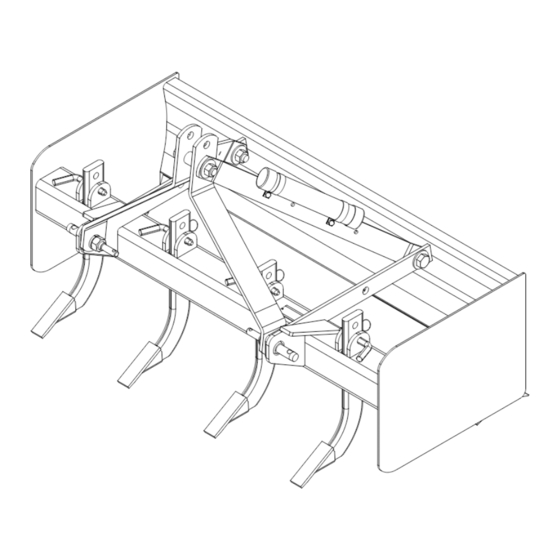
- Page 1 BOX SCRAPER GBC48 MAN0179_2023-06.indd 1 MAN0179_2023-06.indd 1 2/8/24 9:43 AM 2/8/24 9:43 AM...
-
Page 2: Introduction
TO THE OWNER: Read this manual before operating your Woods equipment. The information presented will prepare you to do a better and safer job. Keep this manual handy for ready reference. Require all operators to read this manual carefully and become acquainted with all adjustment and operating procedures before attempting to operate. -
Page 3: Table Of Contents
TABLE OF CONTENTS INTRODUCTION..........2 WARRANTY INFORMATION . -
Page 4: Specifications
SPECIFICATIONS GBC48 Overall Width 48" Weight 285 lbs. Cutting Edge 1/2" x 6" x 47" Reversible Moldboard Thickness 7 - gauge Side Plate Thickness 7 - gauge Scarifier Adjustable, 3 Position with replaceable wear points Capacity 9 cu.ft. Tractor Rating Max. -
Page 5: Safety Rules
SAFETY RULES ATTENTION! BECOME ALERT! YOUR SAFETY IS INVOLVED! ■ Power unit must be equipped with ROPS or ROPS cab and seat belt. Keep seat belt secure- Safety is a primary concern in the design and man- ly fastened. Falling off power unit can result in ufacture of our products. -
Page 6: Transportation
SAFETY RULES ATTENTION! BECOME ALERT! YOUR SAFETY IS INVOLVED! ■ Use extreme care when working close to fences, ■ Never go underneath equipment (lowered to the ditches, other obstructions, or on hillsides. ground or raised) unless it is properly blocked and secured. -
Page 7: Safety Decals
ROPS (or ROPS CAB) Replacement safety decals can be ordered and seat belt. Keep foldable free from your Woods dealer. To locate your ROPS systems in "locked up" position at all times. nearest dealer, check the Dealer Locator at Buckle Up! Keep seat belt ... -
Page 8: Operation
OPERATION The operator is responsible for the safe operation of PRE-OPERATION CHECKLIST this equipment. The operator must be properly trained. Operators should be familiar with the equipment, the (OWNER’S RESPONSIBILITY) tractor, and all safety practices before starting opera- tion. Read the safety rules and safety decals on page 5 Review and follow all safety rules and safety through page 7. -
Page 9: Adjusting Top Link
Figure 1. 3-Point Lower Lift Arms Connected Figure 3. Sleeve Locations Quick Hitch (Category 1 Only) The GBC48 will attach to a Category 1 quick hitch. 1. Use Bushing Kit 1004653 when using a quick cou- pler. See parts section for a list of parts. -
Page 10: Scarifying
SCARIFYING LEVELING 1. Place the scarifier shanks in position with the points 1. Raise or remove scarifier shanks. facing toward the tractor. 2. Shorten the top link so the cutting edge clears the 2. Lock into position with the pins provided. The ground. -
Page 11: Owner Service 11
OWNER SERVICE The information in this section is written for operators REPLACING CUTTING EDGE who possess basic mechanical skills. If you need help, your dealer has trained service technicians available. To service the box scraper when attached to the trac- For your protection, read and follow the safety informa- tor, it must be blocked up off the ground. -
Page 12: Replacing Scarifier Shank Tooth
■ Sand down scratches and the edges of areas 1. Remove scarifier shank (1) from the scarifier bar. missing paint and coat with Woods spray paint 2. Remove the worn tooth by driving a chisel between of matching color (purchase from your Woods the shank (1) and tooth (2) . -
Page 13: Assembly 13
1. Remove banding that holds box scraper to pallet. Assembly of this Box Scraper is the responsibility of the WOODS dealer. It should be delivered to the owner 2. Remove lag bolts securing A-frame support bars (8) completely assembled, lubricated and adjusted for nor- to the pallet. -
Page 14: Assemble Box Scraper
ASSEMBLE BOX SCRAPER 1. Place A-frame bars (6) over mounting pins on the inside of scraper frame. 2. Secure with lock washers (30) and hex nuts (31) previously removed from mounting pins. 3. Attach A-frame support bars (8) to the scraper frame and secure with cap screws (28), lock washers (27), and hex nuts (26) previously removed. -
Page 15: Dealer Checklists 15
DEALER CHECKLISTS DEALER PRE-DELIVERY CHECKLIST DEALER DELIVERY CHECKLIST (DEALER’S RESPONSIBILITY) (DEALER’S RESPONSIBILITY) Show customer the safe, proper procedures Inspect the equipment thoroughly after assembly to to be used when mounting, dismounting, and be certain it is set up properly before delivering it to storing equipment. - Page 16 NOTES 16 Notes MAN0179 ( 06/07/2023 ) MAN0179_2023-06.indd 16 MAN0179_2023-06.indd 16 2/8/24 9:43 AM 2/8/24 9:43 AM...
-
Page 17: Parts 17
GBC48 BOX SCRAPER CD6170B PART DESCRIPTION PART DESCRIPTION 32295 Cutting edge, 1/2 x 6 x 47 1450 *3 3/4 NC Hex nut Scarifier & tip assembly 2522 *3 3/4 Lock washer 1035770 (includes item 4) 735 *2 3/4 NC x 2 Cap screw GR5 1005338 Bent pin, .62 x 3.0 w/clip... - Page 18 1009298 HITCH PIN KIT (OPTIONAL) PART DESCRIPTION 1009298 Kit, Cat 0/1 hitch pin Hitch pin Cat 0/1 1004626 (includes items 2 & 3) 30008 *2 7/8 Lock washer 30007 *2 7/8 Hex nut NF Standard Hardware, obtain locally N/A Not Available CD6640 1009297 MANUAL TUBE KIT (OPTIONAL) PART...
- Page 19 1004653 QUICK HITCH BUSHING KIT (OPTIONAL) CD6222 PART DESCRIPTION 1004660 Sleeve .938 x 1.438 x 1.19 27542 *2 7/16 x 11/32 Klik pin Standard Hardware, obtain locally Parts 19 MAN0179 ( 06/07/2023 ) MAN0179_2023-06.indd 19 MAN0179_2023-06.indd 19 2/8/24 9:43 AM 2/8/24 9:43 AM...
-
Page 20: Appendix
BOLT TORQUE CHART Always tighten hardware to these values unless a different torque value or tightening procedure is listed for a specific application. Fasteners must always be replaced with the same grade as specified in the manual parts list. Always use the proper tool for tightening hardware: SAE for SAE hardware and Metric for metric hardware. Make sure fastener threads are clean and you start thread engagement properly. -
Page 21: Bolt Size Chart & Abbreviations
BOLT SIZE CHART NOTICE: Chart shows bolt thread sizes and corresponding head (wrench) sizes for standard SAE and metric bolts. SAE BOLT THREAD SIZES 5/16 10mm 12mm 14mm 16mm 18mm METRIC BOLT THREAD SIZES ABBREVIATIONS AG ....Agriculture HT . - Page 22 Woods logo are trademarks of Woods Equipment Company. All other ® trademarks, trade names, or service marks not owned by Woods Equipment Company that appear in this manual are the property of their respec tive companies or mark holders. Specifications subject to change without notice.