Table of Contents
Advertisement
Quick Links
LC-121M2U
LC-150M2U
In the interests of user-safety (Required by safety regulations in some countries) the set should be restored to its original
condition and only parts identical to those specified be used.
1. IMPORTANT SERVICE SAFETY PRECAUTION .................................................................................... 2
2. SPECIFICATIONS ................................................................................................................................... 4
3. PART NAMES .......................................................................................................................................... 5
4. DISASSEMBLY OF THE SET .................................................................................................................. 6
5. ADJUSTING PROCEDURE OF EACH SECTION ................................................................................... 8
6. INTEGRATED CIRCUIT TERMINAL ARRANGEMENTS ........................................................................ 19
7. TROUBLE SHOOTING TABLE ................................................................................................................ 24
8. CHASSIS LAYOUT .................................................................................................................................. 29
9. SCHEMATIC DIAGRAM .......................................................................................................................... 32
10. BLOCK DIAGRAM ................................................................................................................................... 47
11. PRINTED WIRING BOARD ASSEMBLIES .............................................................................................. 49
12. REPLACEMENT PARTS LIST ................................................................................................................. 54
13. PACKING OF THE SET ........................................................................................................................... 65
SHARP CORPORATION
SERVICE MANUAL
MODELS
CONTENTS
This document has been published to be used for
after sales service only.
The contents are subject to change without notice.
1
SX8Z8LC-121M2U
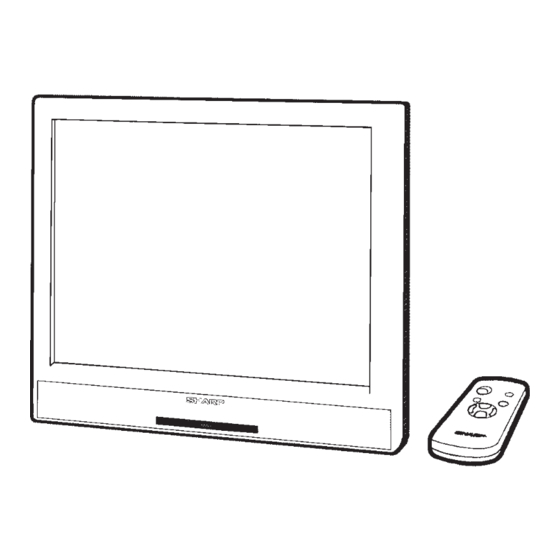
LCD AV MONITOR
LC-121M2U
LC-150M2U
LC-121M2U
LC-121M2U
LC-150M2U
LC-150M2U
Page
Advertisement
Table of Contents

Related Manuals for Sharp LC-121M2U


Summary of Contents for Sharp LC-121M2U
-
Page 1: Table Of Contents
LC-121M2U LC-121M2U LC-121M2U LC-150M2U LC-150M2U LC-150M2U SERVICE MANUAL SX8Z8LC-121M2U LCD AV MONITOR LC-121M2U LC-150M2U MODELS In the interests of user-safety (Required by safety regulations in some countries) the set should be restored to its original condition and only parts identical to those specified be used. -
Page 2: Important Service Safety Precaution
LC-121M2U LC-121M2U LC-150M2U LC-150M2U 1. IMPORTANT SERVICE SAFETY PRECAUTION æ Service work should be perfomed only by qualified service technicians who are thoroughly familiar with all safety checks and servicing guidelines which follow: WARNING Any reading of 0.3V RMS(this corresponds to 0.2 milliamp. - Page 3 LC-121M2U LC-121M2U LC-150M2U LC-150M2U 1. PRECAUTIONS A PRENDRE LORS DE LA REPARATION Æ Æ Æ Æ Æ Ne peut effectuer la réparation qu’ un technicien spécialisé qui s’est parfaitement accoutumé à toute vérification de sécurité et aux conseils suivants. AVERTISSEMENT Il faut répéter les vérifications en inversant la...
-
Page 4: Specifications
DC12V, VHS, S-VHS, Audio and DVD Output: VHS, S-VHS, Audio and Headphone Power Source: AC 100~240·50/60Hz (Connected to AC Adapter) Power Consumption (Approx.): 38 W (Connected to AC Adapter) (LC-121M2U) 40 W (Connected to AC Adapter) (LC-150M2U) Operating Temparature: –10°C~40°C Dimensions: 297.4 mm (W) ×... -
Page 5: Part Names
LC-121M2U LC-121M2U LC-150M2U LC-150M2U 3. PART NAMES... -
Page 6: Disassembly Of The Set
5. Disconnect each connectors (9~e) from the LCD display unit. 6. Remove the cabinet A. Cabinet B Push Cabinet B c WH Cabinet A b WH Cable Cabinet B Cabinet A CCABA2338CE02 GCABA2338CEKA (LC-121M2U) CCABB2246CE02 GCABB2246CEKA (LC-121M2U) CCABA2343CE02 GCABA2343CEKA (LC-150M2U) CCABB2249CE02 GCABB2249CEKA (LC-150M2U) - Page 7 12. Remove one screw (o) and remove the SOS shield angle. 13. Remove four screws (p) which mounting the LCD display unit. 14. Spread bites of the LCD unit (a) out to be off from claws. 15. Remove the Lamp unit (s). Holder LHLDZ2082CEKZ (LC-121M2U) LHLDZ2085CEKZ (LC-150M2U)
-
Page 8: Adjusting Procedure Of Each Section
LC-121M2U LC-121M2U LC-150M2U LC-150M2U 5. ADJUSTING PROCEDURE OF EACH SECTION The best adjustment is made before shipping. If any position deviation is found or after part replace is performed, adjust as follows. 5-1. Preparation for adjustment (1)Use the exclusive-use AC adapter or stable DC power supply. - Page 9 LC-121M2U LC-121M2U LC-150M2U LC-150M2U 5-3. Cancel of special mode Turn off the main unit power. 5-4. Preparation adjustment (1)Use the exclusive-use AC adapter or stable DC power supply. AC adapter: UADP-0183CEZZ DC power supply: 12 ± 0.5V 5-5. OSD menu indication and items in case of manual adjustment...
- Page 10 LC-121M2U LC-121M2U LC-150M2U LC-150M2U PAL/SECAM OSC PAL BRIGHTNESS PAL UNICOLOR PAL SCOLOR PAL TINT BELL F0 B-Y BLACK LEVEL R-Y BLACK LEVEL SECAM BRIGHTNESS SECAM UNICOLOR SECAM COLOR SECAM TINT DVD NT BRIGHTNESS DVD NT UNICOLOR DVD NT COLOR DVD NT TINT...
- Page 11 LC-121M2U LC-121M2U LC-150M2U LC-150M2U DAC 2 1ch Fixed DAC 2 2ch Fixed DAC 2 3ch Fixed DAC 2 4ch Fixed DAC 2 5ch Fixed DAC 2 6ch Fixed DAC 2 7ch Fixed DAC 2 8ch Fixed DAC 2 9ch Fixed...
- Page 12 LC-121M2U LC-121M2U LC-150M2U LC-150M2U 5-6-2. AV input Adjustment Adjustment Adjustment conditions Adjustment method Brightness adjustment 1. Input the standard color bar signal 1. Adjust N358 BRIGHTNESS, and (N358) (the same pattern as that of JPN-8CH) adjust the black level of G output so of N358 into AV1.
- Page 13 LC-121M2U LC-121M2U LC-150M2U LC-150M2U B DRIVE adjustment 1. Input the standard color bar signal 1. Adjust so as to get 100% white level (the same pattern as that of JPN- identical with that of green. 8CH) of N358 into AV1.
- Page 14 LC-121M2U LC-121M2U LC-150M2U LC-150M2U Brightness adjustment 1. Input the standard color bar signal 1. Adjust PAL BRIGHTNESS, and (PAL) of PAL into AV1. adjust the black level of G output 2. Connect oscilloscope to TP821 so as to get DC 1.5±0.05V.
- Page 15 LC-121M2U LC-121M2U LC-150M2U LC-150M2U BELL f0 adjustment 1. Connect the oscilloscope to 1. Adjust BELL f0 so as to minimize the TP2851. a-level. Brightness adjustment 1. Input the standard color bar signal 1. Adjust SECAM BRIGHTNESS, and (SECAM) (the same pattern as that of E-10CH) adjust the black level of G output to of SECAM into AV1.
- Page 16 LC-121M2U LC-121M2U LC-150M2U LC-150M2U 5-6-3. Component input Adjustment Adjustment Adjusting conditions Adjusting method Brightness adjustment 1. From SG, input the 100% white color Adjust DVD NT BRIGHTNESS, and (NTSC) bar signal of NTSC into conponent adjust the black level of G output so terminal.
- Page 17 LC-121M2U LC-121M2U LC-150M2U LC-150M2U Brightness adjustment 1. From SG, input the 100% white color Adjust DVD PAL BRIGHTNESS, and (PAL) bar signal of PAL into conponent adjust the black level of G output so terminal. as to get DC 1.5±0.05V.
- Page 18 LC-121M2U LC-121M2U LC-150M2U LC-150M2U 5-7. Shipping setting (1)[Procedure] Holding down the [AV INPUT] key and [MENU] key, turn on the main power, and simultaneously press the (inspection process) [SELECT '] key and [VOL+] key to change the mode to the adjustment mode.
-
Page 19: Integrated Circuit Terminal Arrangements
LC-121M2U LC-121M2U LC-150M2U LC-150M2U 6. INTEGRATED CIRCUIT TERMINAL ARRANGEMENTS 1. IC2001 (QFP, 80pins) Terminal No. Terminal name Function N. C – N. C – KEY3 Key input 3 KEY4 Key input 4 HPDET Headphon input pickup Audio selection 1 Audio selection 2... - Page 20 LC-121M2U LC-121M2U LC-150M2U LC-150M2U Terminal No. Terminal name Function Empty Micro computer power off output SECAM “H” in SECAM mode, “L” in other modes. “H” in PAL mode, “L” in other modes. N. C – N. C – N. C –...
- Page 21 LC-121M2U LC-121M2U LC-150M2U LC-150M2U 2. IC1201 (QFP, 128pins) Terminal No. Voltage Signal name Function 5.0V OSD_BK OSD Blanking input 5.0V OSD_R OSD R input 5.0V OSD_G OSD G input 5.0V OSD_B OSD B input 5.0V OSDVD OSD V output 5.0V...
- Page 22 LC-121M2U LC-121M2U LC-150M2U LC-150M2U Terminal No. Voltage Signal name Function 3.3V 3.3V 3.3V HDCK SOURCE driver control signal output 1 3.3V SOURCE driver control signal output 2 3.3V 3.3V OOG1 G output 1 3.3V OOG0 G output 0 (LSB) 3.3V...
- Page 23 LC-121M2U LC-121M2U LC-150M2U LC-150M2U Terminal No. Voltage Signal name Function 3.3V 3.3V TST8 Test input 8 3.3V TST7 Test input 7 3.3V TST6 Test input 6 3.3V TST5 Test input 5 3.3V TST4 Test input 4 3.3V TST3 Test input 3 3.3V...
- Page 24 LC-121M2U LC-121M2U LC-150M2U LC-150M2U 7. TROUBLESHOOTING...
- Page 25 LC-121M2U LC-121M2U LC-150M2U LC-150M2U...
- Page 26 LC-121M2U LC-121M2U LC-150M2U LC-150M2U...
- Page 27 LC-121M2U LC-121M2U LC-150M2U LC-150M2U...
- Page 28 LC-121M2U LC-121M2U LC-150M2U LC-150M2U...
-
Page 29: Chassis Layout
LC-121M2U LC-121M2U LC-150M2U LC-150M2U 8. CHASSIS LAYOUT P751 IC2801 1H Dilay system TP805 P2002 IC853 P2001 IC801 Chroma decoder Digital comb filter T751 SECAM decoder T752 IC2802 TP804 X2850 Inverter transformer TP1106 TP1112 T701 IC1201 DC/DC Transformer Controller F701 TP1111 P402 125V 1.6A... - Page 30 LC-121M2U LC-121M2U LC-150M2U LC-150M2U • DESCRIPTION OF SCHEMATIC DIAGRAM 1. When the exclusive-use AC adapter is used, the color bar signal of color bar generator for service is input to get the normal screen. When the audio is minimized, the voltage value is measured with the 20 kΩ/V tester.
- Page 31 LC-121M2U LC-121M2U LC-150M2U LC-150M2U...
- Page 32 LC-121M2U LC-121M2U LC-150M2U LC-150M2U 9. SCHEMATIC DIAGRAM: JACK UNIT...
- Page 33 LC-121M2U LC-121M2U LC-150M2U LC-150M2U SCHEMATIC DIAGRAM: MAIN CIRCUIT (1)
- Page 34 LC-121M2U LC-121M2U LC-150M2U LC-150M2U SCHEMATIC DIAGRAM: MAIN CIRCUIT (2), REMOTE CONTROL UNIT, SWITCH UNIT (LC-121M2U)
- Page 35 LC-121M2U LC-150M2U...
-
Page 36: Schematic Diagram
LC-121M2U LC-150M2U SCHEMATIC DIAGRAM: MAIN CIRCUIT (2), REMOTE CONTROL UNIT, SWITCH UNIT (LC-150M2U) - Page 37 LC-121M2U LC-121M2U LC-150M2U LC-150M2U...
- Page 38 LC-121M2U LC-121M2U LC-150M2U LC-150M2U SCHEMATIC DIAGRAM: MAIN CIRCUIT (3) (LC-121M2U)
- Page 39 LC-121M2U LC-150M2U...
- Page 40 LC-121M2U LC-150M2U SCHEMATIC DIAGRAM: MAIN CIRCUIT (3) (LC-150M2U)
- Page 41 LC-121M2U LC-121M2U LC-150M2U LC-150M2U...
-
Page 42: Block Diagram
LC-121M2U LC-121M2U LC-150M2U LC-150M2U 10. BLOCK DIAGRAM IC312 IC310,311 IC308 Sound control IC305 Audio selection Lateral inversion Speaker Audio Amplifer Q306,307 IC304 AV2 SOUND L,R AV1 SOUND L,R COMPONENT SOUND L,R Q703 Switch IC704 PWM control AV2 picture AV2 input... - Page 43 LC-121M2U LC-121M2U LC-150M2U LC-150M2U 11. PRINTED WIRING BOARD ASSEMBLIES MAIN UNIIT (Component Side)
- Page 44 LC-121M2U LC-121M2U LC-150M2U LC-150M2U MAIN UNIIT (Wiring Side)
- Page 45 LC-121M2U LC-150M2U JACK/REMOTE CONTROL RECEPTOR/SWITCH UNIT REMOTE CONTROL RECEPTOR UNIT JACK P.W.B. Component Side Wiring Side Component Side Wiring Side SWITCH UNIT Component Side Wiring Side...
-
Page 46: Printed Wiring Board Assemblies
2. NO. DE REF 3. NO. DE PIECE 4. DESCRIPTION in USA : Contact your nearest SHARP Parts Distributor to order. For location of SHARP Parts Distributor, Please call Toll-Free: in CANADA : Contact SHARP Electronics of Canada Limited Phone... - Page 47 LC-121M2U LC-121M2U LC-150M2U LC-150M2U Ref. No. Part No. Description Code Ref. No. Part No. Description Code DUNTK9775DE01 (LC-121M2U) D2006 VHDiMN10///-1 J Diode DUNTK9775DE02 (LC-150M2U) PACKAGED CIRCUITS MAIN UNIT (Continued) X801 RCRSB0262CEZZ J Crystal IC2005 VHiTC4W66F/-1 J TC4W66F X802 RCRSB0263CEZZ J Crystal...
- Page 48 LC-121M2U LC-121M2U LC-150M2U LC-150M2U Ref. No. Part No. Description Code Ref. No. Part No. Description Code DUNTK9775DE01 (LC-121M2U) C732 VCEAPW0JN477M J 470 6.3V Electrolytic DUNTK9775DE02 (LC-150M2U) C733 VCEAPW0JN477M J 470 6.3V Electrolytic MAIN UNIT (Continued) C734 VCKYTV1CF105Z 16V Ceramic C735 VCEAPW0JN477M J 470 6.3V Electrolytic...
- Page 49 LC-150M2U LC-150M2U Ref. No. Part No. Description Code Ref. No. Part No. Description Code DUNTK9775DE01 (LC-121M2U) C1039 VCCCCY1HH101J J 100p 50V Ceramic DUNTK9775DE02 (LC-150M2U) C1040 VCCCCY1HH101J J 100p 50V Ceramic MAIN UNIT (Continued) C1041 VCCCCY1HH101J J 100p 50V Ceramic C1042...
- Page 50 LC-121M2U LC-121M2U LC-150M2U LC-150M2U Ref. No. Part No. Description Code Ref. No. Part No. Description Code DUNTK9775DE01 (LC-121M2U) C2807 VCKYCY1EF104Z J 0.1 25V Ceramic DUNTK9775DE02 (LC-150M2U) C2808 VCKYCY1EF104Z J 0.1 25V Ceramic MAIN UNIT (Continued) C2809 VCEAPF1HW474M J 0.47 50V Electrolytic...
- Page 51 LC-121M2U LC-150M2U LC-150M2U Ref. No. Part No. Description Code Ref. No. Part No. Description Code DUNTK9775DE01 (LC-121M2U) R735 VRS-CY1JF122F J 1.2k 1/16W Metal Oxide AA DUNTK9775DE02 (LC-150M2U) R736 VRS-TX2HF681J J 680 1/2W Metal Oxide AA MAIN UNIT (Continued) R737 VRS-CY1JF102J...
- Page 52 LC-121M2U LC-150M2U LC-150M2U Ref. No. Part No. Description Code Ref. No. Part No. Description Code DUNTK9775DE01 (LC-121M2U) R1142 VRS-CY1JF000J 1/16W Metal Oxide AA DUNTK9775DE02 (LC-150M2U) R1145 VRS-CY1JF000J 1/16W Metal Oxide AA MAIN UNIT (Continued) R1146 VRS-CY1JF000J 1/16W Metal Oxide AA...
- Page 53 LC-121M2U LC-121M2U LC-150M2U LC-150M2U Ref. No. Part No. Description Code Ref. No. Part No. Description Code DUNTK9775DE01 (LC-121M2U) FB708 RBLN-0090CEZZ J Balun DUNTK9775DE02 (LC-150M2U) FB709 RBLN-0095CEZZ J Balun MAIN UNIT (Continued) FB710 RBLN-0090CEZZ J Balun FB801 RBLN-0035TAZZ J Balun R1818...
- Page 54 2-24 2-22 2-23 2-17 2-20 2-14 2-15 Switch Unit (RUNTK0635CEZZ) 2-16 2-11 2-21 LC-150M2U Main Unit (DUNTK9775DE01/02) Jack Unit (RUNTK0633CEZZ) 1-24 1-23 LC-121M2U 1-21 1-12 1-10 1-17 (Only LC-121M2U ) 1-16 1-15a 1-15b 1-10 1-12 1-20 Remote Control Unit (RUNTK0634CEZZ)
- Page 55 PSHEP0169CEZZ J D-BEF Sheet(LC-150M2U) BH GCOVA1747CESA J R/C Receptor Cover PSHEP0164CEZZ J Wave Sheet(LC-150M2U) AX HBDGB3143CESB J Sharp Badge PSLDM4483CEFW J Shield Case(LC-121M2U) AN (LC-150M2U) PSLDM4484CEFW J Shield Case(LC-150M2U) AQ HBDGB3143CESB J Sharp Badge QCNW-4941CEZZ J LCD Cable (LC-121M2U) (LC-121M2U)
- Page 56 Description Code SUPPLIED ACCESSORIES PACKING PARTS (NOT REPLACEMENT ITEM) ACCESSORIES LANGU9041CESA J Wall Mount Bracket SPAKC5316CEZZ – Packing Case(LC-121M2U) — å QACCD3088CEZZ J AC Cable SPAKC5335CEZZ – Packing Case(LC-150M2U) — RRMCG1459CESA J Remote Control (From 1st to 137th unit) TiNS-6528CEZZ...
-
Page 57: Packing Of The Set
SPAKF0401CEZZ(LC-150M2U) (Packing ADD.) SSAKA0160CEZZ (Polyethylene Bag) SPAKP0782CEZZ TiNS-6528CEZZ (LC-121M2U) (Operation Manual) SPAKP0785CEZZ (LC-150M2U) (Wrapping Paper) Battery LC-121M2U LC-150M2U SPAKX2875CEZZ (LC-121M2U) SPAKX2881CEZZ (LC-150M2U) (Packing ADD.) RRMCG1459CESA (Remote Control) UADP-0183CEZZ (AC Adapter) SPAKF0403CEZZ(LC-121M2U) SPAKF0418CEZZ(LC-150M2U) (Packing ADD.) QACCD3088CEZZ (AC Cable) LANGU9041CESA TLABN0157CEZZ (Wall Mount Bracket) (No. - Page 58 Code Ref. No. Part No. Description Code COPYRIGHT C 1998 BY SHARP CORPORATION ALL RIGHTS RESERVED. No part of this publication may be reproduced, stored in a retrieval system, or transmitted in any form or by any means, electronic, mechanical, photocopying, recording, or otherwise, without prior written permission of the publisher.