Watchguard Firebox X1000 Hardware Manual
Firebox x series
Hide thumbs
Also See for Firebox X1000:
- User manual (314 pages) ,
- Reference manual (264 pages) ,
- Quick start manual (38 pages)

Related Manuals for Watchguard Firebox X1000


Summary of Contents for Watchguard Firebox X1000
- Page 1 ® Firebox Hardware Guide Firebox® X500, Firebox® X700, Firebox® X1000, Firebox® X2500...
-
Page 2: Limited Hardware Warranty
WatchGuard, the WatchGuard logo, Firebox LiveSecurity, and any other mark listed as a trademark in the “Terms of Use” portion of the WatchGuard Web site that is used herein are either registered trademarks or trademarks of WatchGuard Technologies, Inc. and/or it’s subsidiaries in the United States and/or other courtries. - Page 3 2. REMEDIES. If any Product does not comply with the WatchGuard warranties set forth in Section 1 above, WatchGuard will, following receipt of the product you claim is defective and at its option, either (a) repair the Product, or (b) replace the Product;...
- Page 4 PERFORMANCE OF THE ENTITY’S OBLIGATIONS UNDER THE WARRANTY DO NOT VIOLATE ANY THIRD-PARTY AGREEMENT TO WHICH THE ENTITY IS A PARTY. No change or modification of the Warranty will be valid unless it is in writing and is signed by WatchGuard.
-
Page 5: Declaration Of Conformity
Declaration of Conformity Declaration of Conformity Hardware Guide... -
Page 6: Fcc Certification
This device must accept any interference received, including interference that may cause undesired operation. CE Notice The CE symbol on your WatchGuard Technologies equipment indicates that it is in compliance with the Electromagnetic Compatibility (EMC) directive and the Low Voltage Directive (LVD) of the European Union (EU). -
Page 7: Vcci Notice Class A Ite
VCCI Notice Class A ITE VCCI Notice Class A ITE Hardware Guide... - Page 8 viii...
-
Page 9: Table Of Contents
Contents Limited Hardware Warranty Declaration of Conformity ... v FCC Certification CE Notice ... vi Industry Canada ... vi VCCI Notice Class A ITE ... vii Package Contents ...2 Hardware Specifications Environmental Requirements Hardware Description Firebox® X front panel Firebox® X rear view Hardware Guide ...ii ... -
Page 11: Hardware Guide
Hardware Guide The WatchGuard® Firebox® X is the world’s first key-upgrade- able integrated security appliance. Its Intelligent Layered Secu- rity architecture delivers multiple layers of protection that work together to detect and block threats from attacking your net- work. Stateful firewall, VPN, intrusion prevention, application... -
Page 12: Package Contents
3 straight-through Ethernet cables (green) • 1 cross-over Ethernet cable (red) • 1 serial cable (blue) • 1 DB9 adapter • 1 rack-mounting kit • WatchGuard System Manager CD • Firebox X documentation pack • LiveSecurity • License key • Warranty card ®... -
Page 13: Hardware Specifications
Network interfaces Serial ports Power supply Dimensions Weight Environmental Requirements WatchGuard recommends physically installing a Firebox X device under the following conditions: • Securely rack-mounted • Placed in a secured environment, such as a locked LAN room, or similar space, to prevent physical compromise by unprivileged personnel •... -
Page 14: Hardware Description
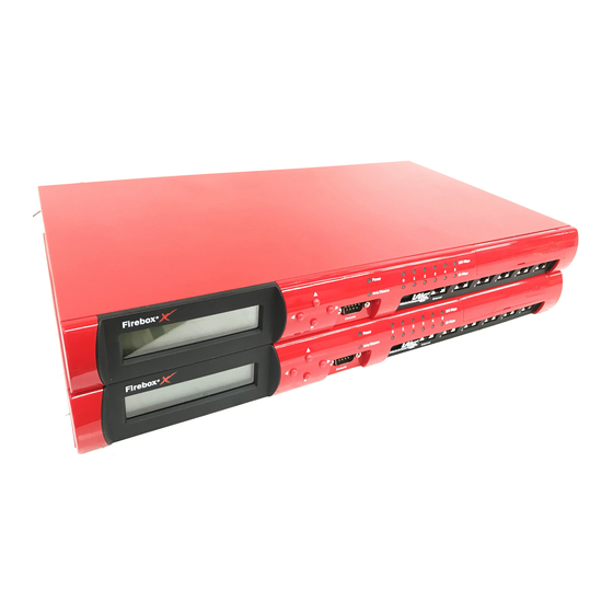
The following table shows other environmental requirements. Operating temperature Operating humidity Non-operating temperature Non-operating humidity Non-operating random vibration Acoustic noise Operating mechanical shock Hardware Description Firebox® X front panel The following photograph shows the entire front view. 0 – 40 degrees Celsius (+32 – 104 degrees Fahrenheit) 10% –... - Page 15 The photograph below shows a close-up of the left side of the indicator panel. From the left, the indicators are as follows: Front Panel Display The LCD screen displays Firebox X status information. Use the buttons to change the information that appears.
-
Page 16: Firebox® X Rear View
The photograph below shows a close-up of the right side of the indicator panel. From the left, the indicators and connections are as follows. Interface ports The six ports have standard RJ45 connectors and are labeled External (0), 1, 2, 3, 4, and 5. Each port has a corresponding LED located above the interface ports. - Page 17 AC Receptacle Accepts the detachable AC power cord supplied with the Firebox X. The power supply for the Firebox X is a WatchGuard standard auto-sensing AC power supply. Power Switch Turns the Firebox X on or off. Hardware Guide Hardware Description...