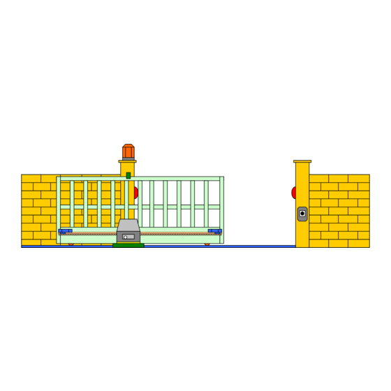
Summary of Contents for ECA SL-450ECA
- Page 1 INSTALLATION MANUAL for MODEL: SL-450ECA ECA Electronic Engineering Pty. LTD. Australia Tel: 03-95720 535 Fax: 95 720 536 Owner’s Manual Sliding Gate Motor Model: SL-450 ECA (Version 1)
-
Page 2: Specification
INSTALLATION MANUAL for MODEL: SL-450ECA 1 Introduction 1.0 Specification : Maximum Gate Weight : 400Kg Speed: 17cm/Sec. Power supply: 220 - 245V AC / 50Hz Motor type: 12VDC Backup battery: 12VDC / 4AH. 1.1 Inclusion Description Q’ty MOTOR Override Key... - Page 3 INSTALLATION MANUAL for MODEL: SL-450ECA 2.0 Before you start installing the operator, please check 2.0.1 Make sure of the flatness of the installation site. Installation on a slope land may cause an unexpected abnormal situation. 2.0.2 Make sure the gate wheels have been mounted properly and are in good condition.
- Page 4 INSTALLATION MANUAL for MODEL: SL-450ECA 2.2.8 Turn the release key clockwise and open the cover, the operator can be released. Push the door manual along the rack to check if the transmission from the operator gear to the rack is smooth and if the positions of the limit stoppers are correct.
- Page 5 INSTALLATION MANUAL for MODEL: SL-450ECA 240V AC power input Anti-Crash sensor adjustment Battery Plug 2.3.3. Connections in the control panel Description Input / output output LIGHT Normally Open and Common contacts of the light relay for courtesy light switching. STOP input Connect to N.C.
-
Page 6: Operation Program
INSTALLATION MANUAL for MODEL: SL-450ECA 3. Automatic SETUP - Setting the opening & closing time After installing the motor, the control panel must be set to learn the opening and closing time as follows: Step 1. Put the gate on manual and open the gate to half open position and re-engage the gate back in gear. - Page 7 INSTALLATION MANUAL for MODEL: SL-450ECA 4.2. Setting the auto close timer This computerized control panel has a programmable auto-close timer that can be set very easily as follows: Step 1. Press and release Push Button “ TIMER” on the control panel and the program LED will turn ON.
- Page 8 INSTALLATION MANUAL for MODEL: SL-450ECA 6.2. Enable / Disable the Photo Sensor function in opening mode The control panel is responding to the photo sensor in closure mode, which will open the gate each time the photo sensor is triggered during closure time. However, you can set the control panel to respond to the photo senor also in the opening mode.
- Page 9 INSTALLATION MANUAL for MODEL: SL-450ECA 8. Remote Control Teaching & Deleting the Memory The control panel’s radio receiver can learn up to 160 remote controls into its memory. It can learn any of the buttons (I), (II) or (III) of the remote control (model TR-4RS) for operating the gates. Button (IV) is reserved for operating Motor-2 only as a pedestrian gate, if required.
- Page 10 INSTALLATION MANUAL for MODEL: SL-450ECA 9. Exploding Diagram 22 23 24...
- Page 11 INSTALLATION MANUAL for MODEL: SL-450ECA KIT440/450 BOM: QUANTIT CODE NAME SPECIFICATION 8xφ12x15L 53112-012401 rod with dome head 11002-064200-1 self-tapping screw M4x15L(cross-recessed socket button head) 53113-013001 bracket 65x103x102.3L(white) 1.4xφ9.4x47Nxφ10.8x66.5L 53112-035001 spring 53112-011501 U-shape bar 10.9x11.1x11.5x75L 24500-000003 battery 12V-4.5AH 11002-204200-1 self-tapping screw ST3.5x15L(cross-recessed socket button head)
- Page 12 INSTALLATION MANUAL for MODEL: SL-450ECA 37 10000-091500-2 hexagon screw M8x30L 38 10004-060700-1 metric screw M4x12L(cross-recessed counter sunk head) 39 53112-035002 spring 1.1xφ9x10Nx41.5L 40 53112-040002 9.1x84L 50x60x60x21(black) 41 53112-066101 cover(side) 8.3x30.7L 42 53112-040001 43 53112-065002 front bracket 122.8x86.9x71.5 44 10002-050400-1 metric screw...
-
Page 13: Warranty
Part V of the Trade Practices Act 1974 to the maximum extent permitted by law. 5. Without limiting the generality of clause 4, ECA disclaims any liability of any nature in respect of any claim or demand for damages or costs or loss which arises out of: Accidental damage or normal wear and tear to the product or to the product’s component;...
