Table of Contents
Advertisement
Quick Links
Becker Avionics GmbH • Baden-Airpark B108 • 77836 Rheinmünster • Germany
+49 (0) 7229 / 305-0 • Fax +49 (0) 7229 / 305-217
http://www.becker-avionics.com • E-mail: info@becker-avionics.com
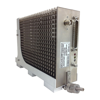
Remote-Controlled
VHF-AM Transceiver
RT6512
RT6512-(100)
RT6512-(200)
RT6512-(201)
Installation and Operation
Manual
DV17501.03
Issue 05
May 2017
Article-No. 0645.702-071
Advertisement
Table of Contents

Related Manuals for Becker RT6512-100


Summary of Contents for Becker RT6512-100
- Page 1 RT6512-(201) Installation and Operation Manual DV17501.03 Issue 05 May 2017 Article-No. 0645.702-071 Becker Avionics GmbH • Baden-Airpark B108 • 77836 Rheinmünster • Germany +49 (0) 7229 / 305-0 • Fax +49 (0) 7229 / 305-217 http://www.becker-avionics.com • E-mail: info@becker-avionics.com...
- Page 2 Becker Avionics GmbH have to be observed. • To the extent that Becker Avionics GmbH provide component or system options based upon data or specifications provided by the user, the user is responsible for determining that such data and specifications are suitable and sufficient for all applications and reasonably foreseeable uses of the components or systems.
- Page 3 Preface Dear Customer, Thank you for purchasing a Becker Avionics product. We are pleased that you have chosen our product and we are confident that it will meet your expectations. For development of our products, the guidelines for highest quality and reliability have been borne in mind, supplemented by selection of high quality material, responsible production and testing in accordance to the ISO 9001 and DIN EN 9100 standards.
- Page 4 Chapter 1 – 4 05/2017 Section / Issue Page No.: Description Chapter 1-60 Changed: Editorial adjustments. 1.5.3 Updated: Descriptions Emergency Mode 2.3.4 Added: More detailed "Antenna Installation" © 2017 by Becker Avionics GmbH / all rights reserved RT6512 DV17501.03 Issue 05 May 2017...
-
Page 5: Table Of Contents
Installation and Operation Table of Contents General Description ........................11 1.1. Introduction..........................12 1.2. Purpose of Equipment ......................... 13 1.3. Variants Overview ........................13 1.4. Associated Devices ........................13 1.5. Scope of Functionality ......................... 14 1.5.1. Receive Mode ........................14 1.5.2. - Page 6 Installation and Operation 2.3. Mounting Requirements ......................32 2.3.1. Mounting Distance ......................32 2.3.2. Grounding .......................... 32 2.3.3. Antenna Cables ......................... 33 2.3.3.1. Attenuation: Cable length versus coax cable type ..........33 2.3.4. Antenna Installation ......................34 2.3.4.1. Required Antenna Type ..................34 2.3.4.2.
- Page 7 Installation and Operation List of Figures Figure 1 Standard Microphone Input Schematic ....................15 Figure 2 LINE_IN Schematic..........................15 Figure 3 LINE_OUT ............................... 15 Figure 4 /FAILURE Output Schematic ........................18 Figure 5: Type Plate (Example) ..........................31 Figure 6:RT6512 with MT6512 - mounting area..................... 32 Figure 7: Antenna Installation ..........................
- Page 8 Installation and Operation List of Abbreviations VSWR Voltage Standing Wave Ratio Units Units Ampere Milliampere °C Degree Celsius Power ratio in Decibel Decibel Foot Gram Inch Kilohertz Megahertz Millimeter Nautical Mile kΩ (kilo Ohm) Resistance kilo Ohm Ohm (Ω) Resistance Part per million Second Volt...
- Page 9 User Conversions and Changes are Not Permitted. Any change on the product, made by the user, excludes any liability of Becker Avionics GmbH. • For installation, opening the device is not required.
- Page 10 Installation and Operation Blank Page RT6512 DV17501.03 Issue 05 May 2017...
-
Page 11: General Description
General Description Introduction General Description In this chapter you can read about: 1.1. Introduction..........................12 1.2. Purpose of Equipment ......................... 13 1.3. Variants Overview ........................13 1.4. Associated Devices ........................13 1.5. Scope of Functionality ......................... 14 1.5.1. Receive Mode ........................14 1.5.2. -
Page 12: Introduction
General Description Introduction 1.1. Introduction The technical information in this manual mainly applies to all variants of the described product. Therefore, we name the product generally with "RT6512" when descriptions are not unique for a product variant. If a description refers to only one of the product variants its full name, e.g. "RT6512-(100)", will be used. -
Page 13: Purpose Of Equipment
RT6512 uses ARINC 429 and RS422 interfaces for communication with a control device. • RT6512 provides frequency and mode control, either by means of the Becker RMU5000 controller using the RS422 communication port, or by means of any OEM product using the standard ARINC 429 communication bus. -
Page 14: Scope Of Functionality
General Description Scope of Functionality 1.5. Scope of Functionality RT6512 performs AM (amplitude modulation) voice communication. Mechanics: Case serves as heat sink mount it proper as defined in chapter "", page 32. Front side contains the main connector (D-Sub 37pin, male) for connection to the aircraft wiring system, and the antenna jack (BNC, female). -
Page 15: Audio Inputs And Outputs
General Description Scope of Functionality 1.5.4. Audio Inputs and Outputs 1.5.4.1. Microphone Input Figure 1 Standard Microphone Input Schematic RT6512 is designed for a standard microphone: • Unbalanced, • DC coupled, • DC supplied from RT6512. The bias current for standard microphone is drawn from RT6512 internal source 15 VDC via series resistor 470 Ohm. -
Page 16: Control Inputs
General Description Scope of Functionality 1.5.5. Control Inputs 1.5.5.1. /ON (Unit Power ON/OFF Control) /ON signal to switch ON/OFF the RT6512. The /ON line is used to activate an internal electronic switch to power-up the unit. It is active if the level on the /ON pin is less than 4.0 V or a resistance of less than 1 kΩ connects to ground. -
Page 17: Serv_En (Enabling The Setup Modes)
General Description Scope of Functionality 1.5.5.6. /SERV_EN (Enabling the Setup Modes) /SERV_EN enables the setup modes. /SERV_EN is a read/write access for all setup data, not available for standard user The device detects a LOW state (Active state) on the /SERV_EN input when an external resistance of lower than 1 kΩ... -
Page 18: Status And Control Outputs
General Description Scope of Functionality 1.5.6. Status and Control Outputs 1.5.6.1. /FAILURE Figure 4 /FAILURE Output Schematic This /FAILURE output is coupled to the status shown at the status LEDs mounted at the connector side of RT6512. It corresponds to OR function of the red and the yellow LEDs. When the test function is not ok, the transistor in the /FAILURE output is ON. -
Page 19: Digital Interfaces To The Control Unit
General Description Scope of Functionality 1.5.7. Digital Interfaces to the Control Unit 1.5.7.1. Interface ARINC 429 Name Function / Remarks ARI429_RX_A1 ARINC 429 Interface RX Line A ARI429_RX_B1 ARINC 429 Interface RX Line B ARI429_TX_A1 ARINC 429 Interface TX Line A ARI429_TX_B1 ARINC 429 Interface TX Line B ARI429_RX_A2... -
Page 20: Safety-Conscious Utilization
General Description Safety-Conscious Utilization 1.6. Safety-Conscious Utilization For safe operation of the product, the following notes have to be observed: • Only an authorized installation company may carry out the installation of the device into an aircraft. The country regulations always have to be observed. •... -
Page 21: Technical Data
General Description Technical Data 1.8. Technical Data 1.8.1. General Characteristics RT6512 Specifications Nominal supply voltage 28.0 VDC Extended supply voltage 22.0…30.3 VDC Emergency operation 18.0 VDC Frequency range RT6512-(100) 118.000...136.9916 MHz RT6512-(200) 118.000...155.975 MHz RT6512-(201) 118.000...155.975 MHz Channel spacing 25 kHz (only, configuration parameter) 8.33/25 kHz (default parameter) Number of channels 8.33 kHz 2280... -
Page 22: Receiver Data
General Description Technical Data 1.8.3. Receiver Data RT6512 Specifications ≤ -93 dBm for a (S+N)/N ratio of 12 dB Sensitivity Effective bandwidth ±2.78 kHz at the 6 dB points (8.33 kHz channel spacing) ±7.37 kHz at the 60 dB points Effective bandwidth ±8 kHz at the 6 dB points (25 kHz channel spacing) -
Page 23: Transmitter Data
General Description Technical Data 1.8.4. Transmitter Data RT6512 Specifications Output power into 50 Ω ≥ 20 W in normal condition; (with and without modulation) (≥ 16 W under all specified environmental conditions) ≤ 5 ppm Frequency tolerance Duty cycle 30 s (TX): 270 s (RX) Type of modulation ≥... -
Page 24: Software
General Description Technical Data 1.8.6. Software As a result of the safety assessment process the failure condition of the RT6512 was determined to be Category MAJOR. As the failure condition of the software used in the RT6512 was categorized MAJOR, the Design Assurance Level (DAL) of the unit is determine to be Level C according DO-178C. -
Page 25: Environmental Conditions
General Description Technical Data 1.8.9. Environmental Conditions The following performance standards were proven under environmental test conditions in accordance with the procedures set forth in EUROCAE/RTCA Document No. ED-14G/DO-160G. Environmental Test Section Category Remarks Temperature and Altitude Ground Survival Low Temperature and 4.5.1 Short-Time Operating Low Short-Time Operating Low Temperature... -
Page 26: Certifications
General Description Technical Data Environmental Test Section Category Remarks Radio frequency susceptibility Conducted Susceptibility: Cat. W Radiated Susceptibility: Cat. W Emission of RF Lightning Induced Transient Susceptibility A3Z3XX Pin tests: Waveform A Level 3 Cable bundle tests: Waveform Z Level 3 Lightning Direct Effects Icing Fire, Flammability... -
Page 27: Fcc Approval
This device must accept any interference received, including interference that may cause undesired operation. NOTE: Changes or modifications made to this equipment not expressly approved by Becker Avionics may void the FCC authorization to operate this equipment. DV17501.03 Issue 05 May 2017... -
Page 28: Order Code
General Description Order Code 1.9. Order Code 1.9.1. RT6512 VHF-AM Transceiver RT6512-(100) Art.-No.: 0644.927-910 Frequency Range 118.000-136.975 MHz RT6512-(200) Art.-No.: 0637.300-910 Frequency Range 118.000-155.975 MHz RT6512-(201) Art.-No.: 0649.643-910 Frequency Range 118.000-155.975 MHz + Emergency Mode 1.9.2. Accessories Mounting Tray Mounting Tray MT6512-(01)*, vertical position Article-No. -
Page 29: Installation
Installation Packaging, Transport, Storage Installation This manual should be available close to the device when performing the tasks below. Careful planning should be applied to achieve the desired performance and reliability from the product. Any deviations from the installation instructions prescribed in this document are under own responsibility. -
Page 30: Device Assignment
Installation Device Assignment Storage If you do not wish to mount and install the device immediately, make sure to store it in a dry and clean environment. Make sure that the device is not stored near strong heat sources and that no metal chippings can get into the device connectors. -
Page 31: Type Plate
Installation Device Assignment 2.2.3. Type Plate The device type defined by the type plate (on the housing). Example: Figure 5: Type Plate (Example) Explanation: P/N: Type designation: RT6512: Remote-Controlled VHF-AM transceiver Options: (100): Frequency Range 118...136.9916 MHz (200): Frequency Range 118...155.975 MHz (201): Frequency Range 118...155.975 MHz + Emergency Mode S/N: Unique number of the particular device... -
Page 32: Mounting Requirements
Installation 2.3. Mounting Requirements The installation of the device(s) depends on the type of aircraft and its equipment and therefore only general information can be given in this section. The device must not be opened after factory exit. When installing the device, make sure the heat dissipator of the device receive sufficient air. -
Page 33: Antenna Cables
Installation Mounting Requirements 2.3.3. Antenna Cables The total attenuation of each antenna connection, including cables, connectors, microwave switch (if used), etc. shall be as low as possible. An aircraft installation should be verified for receiving sensitivity in accordance with ICAO Annex 10, Vol. 3, Part II, §2.3.2.2.1 Observe manufacturer data for characteristic attenuation of the selected cable type, connectors, microwave switch, etc. -
Page 34: Antenna Installation
Installation Mounting Requirements 2.3.4. Antenna Installation For antenna installation, refer always to the manufacturer´s maintenance documentation for the aircraft. Carry out the antenna installation in accordance with AC 43.13-2B Chapter 3. Penetration of the pressurized cabin on a pressurized aircraft requires additional data, which are not contained in this installation manual. - Page 35 Installation Mounting Requirements • Distance to other aircraft antennas (COM, NAV antennas), should be at least 1.5 m/5 ft. • The antenna mounting area should be as flat as possible. • When two radios are used: It is required to have an antenna separation of at least 45 dB. This needs to be guaranteed by the installer.
-
Page 36: Recommendation For Installation Of Two Rt6512 In One Aircraft
In order to minimize the risk of cross talk issues, special care has to be applied during the installation of the antennas, as described in "Antenna Installation" on page 34 of this document. Becker recommends to configure the receiver attenuation functionality in the RT6212 and to perform the related wiring as described here. -
Page 37: Dimensions
Installation Dimensions 2.4. Dimensions 2.4.1. RT6512 Dimensions mm (inch) 38.3±0.15 (0.55 in ±0.006) 14±0.1 (1.59 in ±0.004) Ø5.3±0.05 (Ø0.209 in ±0.002) 30.35±0.15 60±0.15 (1.195 in ±0.006) (2.36 in ±0.006) 30±5 73±5 (1.18 in±0.2) (2.874 in±0.2) CENTER OF GRAVITY Figure 8: RT6512 Dimensions (without and with Main Connector applied) DV17501.03 Issue 05 May 2017 RT6512... -
Page 38: Rt6512 With Mounting Tray Mt6512
Installation Dimensions 2.4.2. RT6512 with Mounting Tray MT6512 Dimensions mm (inch) 71.9±0.3 (2.83 in ±0.019) 31.5±5 32±0.15 (1.24 in±0.2) (1.259 in ±0.006) Ø5.3±0.1 (Ø0.209 in ±0.004) 85±5 (3.346 in±0.2) CENTER OF GRAVITY Figure 9: RT6512 with Mounting Tray MT6512 RT6512 DV17501.03 Issue 05 May 2017... -
Page 39: Connector Pin Assignments
Installation Connector Pin Assignments 2.5. Connector Pin Assignments 2.5.1. Connector P1 (RT6512) Pin Name Function AF_GND Audio ground RESERVE Spare pin for RT6512-(XX0) variants. /EMERG Input which activates the Emergency Mode for RT6512-(201) variant LINE_IN_HI Balanced Line-In HI STD_MIKE_HI Standard microphone input HI LINE_OUT_HI Balanced Line-Out HI SIDETONE... - Page 40 Installation Connector Pin Assignments Pin Name Function ARI429_TX_B2 ARINC 429 Interface TX Line B2 RS422_TX+ RS422 Interface TX Line B (HI if idle) RS422_TX- RS422 Interface TX Line A (LO if idle) Select RS422 communication-port (LO active), if not LO then ARINC 429 /SEL422 ports are active.
-
Page 41: Equipment Configuration Samples
Installation Equipment Configuration Samples 2.6. Equipment Configuration Samples • Selection of active controller type shall be done using /SEL422 line. • ARINC429 Interface or RS422 interface are exclusive (alternative useable). 2.6.1. RT6512 with RMU5000 RT6512 VHF-AM transceiver operated by one RMU5000 using the RS422 interface. Radio RS422 Interface Management Unit... -
Page 42: Aircraft Wiring
Do not apply reverse voltage! If the unit has been powered up with a reverse wiring on the power supply line (ground and DC input reversed) then the unit shall be returned to a Becker Avionics service centre for inspection. -
Page 43: Rt6512-(Xx0) With Arinc 429 Controller
Installation Aircraft Wiring 2.7.1. RT6512-(XX0) with ARINC 429 Controller Aircraft Power Aircraft Power Aircraft Power 28 VDC 28 VDC Ground (from Avionic Master) (from Avionic Master) 10 A ARINC429 Controller RT6512 P1 (male) AWG20 AWG20 AWG20 AWG20 AWG20 AWG20 Note 2 AWG22/24 AWG24/26 Twisted Pair, shielded AWG24/26 Twisted Pair, shielded... -
Page 44: Rt6512-(Xx1) With Arinc 429 Controller
Installation Post Installation Tests 2.7.2. RT6512-(XX1) with ARINC 429 Controller Aircraft Power Aircraft Power Aircraft Power 28 VDC 28 VDC Ground (from Avionic Master) (from Avionic Master) 10 A ARINC429 Controller RT6512 P1 (male) AWG20 AWG20 AWG20 AWG20 AWG20 AWG20 Note 2 AWG22/24 AWG24/26 Twisted Pair, shielded... -
Page 45: Post Installation Tests
Installation Post Installation Tests 2.8. Post Installation Tests Note: It is assumed that the "Installation Setup" has been done before the Post Installation Tests will be carried out. Once the RT6512 is installed completely perform a test procedure to verify system functionality. Ensure compliance with authority required procedures. - Page 46 Installation Post Installation Tests Aircraft System Function NOT OK Audio Generators / Inverters GPS System Compass 1 VHF / NAV1 all channels VHF / NAV 2 all channels Marker Receiver Motor(s) Engine Instruments Stormscope Transponder Air Data Computer Autopilot and Servos •...
-
Page 47: Flight Test Check
Installation Post Installation Tests Channel Frequency (MHz) 121.140 121.1416 121.150 121.1500 121.155 121.1500 121.160 121.1583 121.165 121.1666 121.175 121.1750 121.180 121.1750 121.185 121.1833 121.190 121.1916 121.200 121.2000 121.205 121.2000 121.210 121.2083 131.240 131.2416 131.250 131.2500 131.255 131.2500 131.260 131.2583 131.265 131.2666 131.275 131.2750... - Page 48 Installation Post Installation Tests Blank Page RT6512 DV17501.03 Issue 05 May 2017...
-
Page 49: Operating Instructions
The RT6512 is designed to be operated by means of an remote control device which could be the Becker RMU5000 using the RS422 control bus, or any OEM control device using the ARINC 429 control bus with standard label format. -
Page 50: Start-Up
Operating Instructions Start-Up 3.4. Start-Up 3.4.1. Built In Tests (BIT) The RT6512 has advanced Built-In-Test. It monitors most of internal circuits against failures. In addition BIT monitors some external (installation) conditions to increase RT6512’s reliability. There are three types of BIT implemented: •... -
Page 51: Figure 14 Thermal Behavior For Tx Function
Operating Instructions Start-Up • TX Synthesizer Error RT6512 monitors the TX synthesizer while generating the TX signal. If error behavior is detected and the /PTT input is active (low), RT6512 indicates "TX synthesizer error". This error classifies as "Internal Failure". As long as detecting the "TX Synthesizer Error", the transmitter stays in TX-Off- condition. -
Page 52: Initiated Built In Test (Ibit)
Operating Instructions Start-Up • Stuck PTT Error When the PTT key is pressed a 35 seconds timer starts. When detecting a "Stuck PTT Error", RT6512 switches to the RX-mode. As long as this error is indicated RT6512 stays in a Stuck-PTT-condition. 3.4.1.1. -
Page 53: Error Indication
Audible Error Announcement Behavior in the event of a fault: During flight, switch to another VHF radio and return the unit to a Becker Avionics service centre for repair as soon as landed. RT6512 immediately produce NOGO-audio signal at the LINE_OUT if the error indication is changing from: "no error"... - Page 54 Operating Instructions Start-Up Internal Failure Indication Behavior in the event of a fault: During flight, switch to another VHF radio and return the unit to a Becker Avionics service centre for repair as soon as landed. Output / Indicator Status...
-
Page 55: Arinc 429 Protocol Supported By Rt6512
Operating Instructions ARINC 429 Protocol supported by RT6512 3.5. ARINC 429 Protocol supported by RT6512 The Word Format follows standards ARINC SPECIFICATION 429 PART 1-17 Attachment 6 and GAMA Pub. No 11. Table 1 ARINC word format LABEL (VHF COM) 10 MHz 1 MHz 100 kHz... - Page 56 Operating Instructions ARINC 429 Protocol supported by RT6512 Table 3 The SSM bits description (valid for both 030 and 047 labels) Bit No Function Description 31-30 0 0 – Receive Mode 0 1 – No Computed Data 1 0 – Receive Mode / Self-Test 1 1 –...
- Page 57 Operating Instructions ARINC 429 Protocol supported by RT6512 Channel Channel Channel Name Frequency Spacing 118.000 118.0000 MHz 25 kHz 118.005 118.0000 MHz 8.33 kHz 118.010 118.0083 MHz 8.33 kHz 118.015 118.0166 MHz 8.33 kHz 118.025 118.0250 MHz 25 kHz 118.030 118.0250 MHz 8.33 kHz 118.035...
- Page 58 Operating Instructions ARINC 429 Protocol supported by RT6512 In case of additional questions contact your local Becker Avionics dealer or forward your request direct to Becker Avionics "Customer Service". In the event of damage or a defect, the entire device must be returned for repair. The repair must be performed by trained Becker Avionics personnel.
- Page 59 Operating Instructions ARINC 429 Protocol supported by RT6512 DV17501.03 Issue 05 May 2017 RT6512...
-
Page 60: Index
Warranty Conditions ........9 We reserve the right to make technical changes. The data correspond to the current status at the time of printing. © 2017 by Becker Avionics GmbH / all rights reserved *** End of the Document *** RT6512...