Advertisement
Identifying Your Motherboard Revision
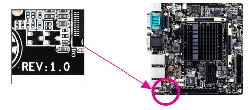
The revision number on your motherboard looks like this: "REV: X.X." For example, "REV: 1.0" means the revision of the motherboard is 1.0. Check your motherboard revision before updating motherboard BIOS, drivers, or when looking for technical information.
Example:
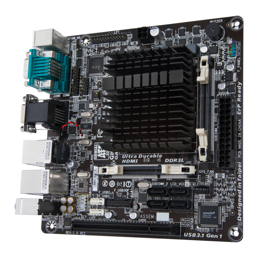
GA-J3455N-D3H Motherboard Layout

Box Contents
- GA-J3455N-D3H motherboard
- Motherboard driver disk
- User's Manual
- Two SATA cables
- I/O Shield
* The box contents above are for reference only and the actual items shall depend on the product package you obtain. The box contents are subject to change without notice.
Hardware Installation
Installation Precautions
The motherboard contains numerous delicate electronic circuits and components which can become damaged as a result of electrostatic discharge (ESD). Prior to installation, carefully read the user's manual and follow these procedures:
- Prior to installation, make sure the chassis is suitable for the motherboard.
- Prior to installation, do not remove or break motherboard S/N (Serial Number) sticker or warranty sticker provided by your dealer. These stickers are required for warranty validation.
- Always remove the AC power by unplugging the power cord from the power outlet before installing or removing the motherboard or other hardware components.
- When connecting hardware components to the internal connectors on the motherboard, make sure they are connected tightly and securely.
- When handling the motherboard, avoid touching any metal leads or connectors.
- It is best to wear an electrostatic discharge (ESD) wrist strap when handling electronic components such as a motherboard, CPU or memory. If you do not have an ESD wrist strap, keep your hands dry and first touch a metal object to eliminate static electricity.
- Prior to installing the motherboard, please have it on top of an antistatic pad or within an electrostatic shielding container.
- Before connecting or unplugging the power supply cable from the motherboard, make sure the power supply has been turned off.
- Before turning on the power, make sure the power supply voltage has been set according to the local voltage standard.
- Before using the product, please verify that all cables and power connectors of your hardware components are connected.
- To prevent damage to the motherboard, do not allow screws to come in contact with the motherboard circuit or its components.
- Make sure there are no leftover screws or metal components placed on the motherboard or within the computer casing.
- Do not place the computer system on an uneven surface.
- Do not place the computer system in a high-temperature or wet environment.
- Turning on the computer power during the installation process can lead to damage to system components as well as physical harm to the user.
- If you are uncertain about any installation steps or have a problem related to the use of the product, please consult a certified computer technician.
- If you use an adapter, extension power cable, or power strip, ensure to consult with its installation and/or grounding instructions.
Product Specifications
| CPU |
|
| Memory |
|
| Onboard Graphics |
|
| Audio |
|
| LAN |
|
| Expansion Slots |
|
| Storage Interface |
|
| USB |
|
| Internal Connectors |
|
| Back Panel Connectors |
|
| I/O Controller |
|
| Hardware Monitor |
|
| BIOS |
|
| Unique Features |
|
| Bundled Software |
|
| Operating System |
|
| Form Factor |
|
* GIGABYTE reserves the right to make any changes to the product specifications and product-related information without prior notice.
Please visit GIGABYTE's website for support lists of memory modules.

Please visit the Support\Utility List page on GIGABYTE's website to download the latest version of apps.

Please visit GIGABYTE's website for details on hardware installation.

Installing the Memory
 Read the following guidelines before you begin to install the memory:
- Make sure that the motherboard supports the memory. It is recommended that memory of the same capacity, brand, speed, and chips be used. (Go to GIGABYTE's website for the latest supported memory speeds and memory modules.)
- Always turn off the computer and unplug the power cord from the power outlet before installing the memory to prevent hardware damage.
- Memory modules have a foolproof design. A memory module can be installed in only one direction. If you are unable to insert the memory, switch the direction.
Dual Channel Memory Configuration
This motherboard provides two memory sockets and supports Dual Channel Technology. After the memory is installed, the BIOS will automatically detect the specifications and capacity of the memory. Enabling Dual Channel memory mode will double the original memory bandwidth. The two memory sockets are divided into two channels and each channel has one memory socket as following:
Channel A: SODIMM_1
Channel B: SODIMM_2
Due to SoC limitations, read the following guidelines before installing the memory in Dual Channel mode.
- If only one DDR3L memory module is to be installed, be sure to install it in the SODIMM_1 socket, and Dual Channel mode cannot be enabled if only one memory module is installed.
- When enabling Dual Channel mode with two memory modules, it is recommended that memory of the same capacity, brand, speed, and chips be used for optimum performance.
Installing an Expansion Card
Read the following guidelines before you begin to install an expansion card:
- Make sure the motherboard supports the expansion card. Carefully read the manual that came with your expansion card.
- Always turn off the computer and unplug the power cord from the power outlet before installing an expansion card to prevent hardware damage.
Back Panel Connectors

- PS/2 Keyboard and PS/2 Mouse Port
Use this port to connect a PS/2 mouse or keyboard and the lower port (purple) to connect a PS/2 keyboard. - Serial Port
Use the serial port to connect devices such as a mouse, modem or other peripherals. - D-Sub Port
The D-Sub port supports a 15-pin D-Sub connector and supports a maximum resolution of 1920x1200@60 Hz (the actual resolutions supported depend on the monitor being used). Connect a monitor that supports D-Sub connection to this port.
- HDMI Port
The HDMI port is HDCP compliant and supports Dolby TrueHD and DTS HD Master Audio formats. It also supports up to 192KHz/24bit 8-channel LPCM audio output. You can use this port to connect your HDMI-supported monitor. The maximum supported resolution is 3840x2160@30 Hz, but the actual resolutions supported are dependent on the monitor being used.
![information]() After installing the HDMI device, make sure to set the default sound playback device to HDMI. (The item name may differ depending on your operating system.)
After installing the HDMI device, make sure to set the default sound playback device to HDMI. (The item name may differ depending on your operating system.)
Dual-Display Configurations for the Onboard Graphics:
Dual-display configurations are supported after you install motherboard drivers in OS. - RJ-45 LAN Port
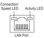
The Gigabit Ethernet LAN port provides Internet connection at up to 1 Gbps data rate. The following describes the states of the LAN port LEDs.
![]()
Connection/Speed LED:
| State | Description |
| Orange | 1 Gbps data rate |
| Green | 100 Mbps data rate |
| Off | 10 Mbps data rate |
Activity LED:
| State | Description |
| Blinking | Data transmission or receiving is occurring |
| Off | No data transmission or receiving is occurring |
- USB 2.0/1.1 Port
The USB port supports the USB 2.0/1.1 specification. Use this port for USB devices. - USB 3.1 Gen 1 Port
The USB 3.1 Gen 1 port supports the USB 3.1 Gen 1 specification and is compatible to the USB 2.0 specification. Use this port for USB devices. - Line In (Blue)
The line in jack. Use this audio jack for line in devices such as an optical drive, walkman, etc. - Line Out (Green)
The line out jack. Use this audio jack for a headphone or 2-channel speaker. This jack can be used to connect front speakers in a 4/5.1/7.1-channel audio configuration. - Mic In (Pink)
The Mic in jack.
 To configure 7.1-channel audio, you have to use an HD front panel audio module and enable the multi-channel audio feature through the audio driver. Please visit GIGABYTE's website for more software information.
- When removing the cable connected to a back panel connector, first remove the cable from your device and then remove it from the motherboard.
- When removing the cable, pull it straight out from the connector. Do not rock it side to side to prevent an electrical short inside the cable connector.
Internal Connectors

- ATX_12V
- ATX
- CPU_FAN
- SYS_FAN
- SATA3 0/1/2/3
- F_PANEL
- F_AUDIO
- BAT
- F_USB30
- F_USB1/F_USB2
- LPT
- TPM
- CLR_CMOS
- CI
Read the following guidelines before connecting external devices:
- First make sure your devices are compliant with the connectors you wish to connect.
- Before installing the devices, be sure to turn off the devices and your computer. Unplug the power cord from the power outlet to prevent damage to the devices.
- After installing the device and before turning on the computer, make sure the device cable has been securely attached to the connector on the motherboard.
1/2) ATX_12V/ATX (2x2 12V Power Connector and 2x12 Main Power Connector)
With the use of the power connector, the power supply can supply enough stable power to all the components on the motherboard. Before connecting the power connector, first make sure the power supply is turned off and all devices are properly installed. The power connector possesses a foolproof design. Connect the power supply cable to the power connector in the correct orientation. The 12V power connector mainly supplies power to the CPU. If the 12V power connector is not connected, the computer will not start.

3/4) CPU_FAN/SYS_FAN (Fan Headers)
The motherboard has a 3-pin CPU fan header (CPU_FAN) and a 4-pin system fan header (SYS_FAN). Most fan headers possess a foolproof insertion design. When connecting a fan cable, be sure to connect it in the correct orientation (the black connector wire is the ground wire). The speed control function requires the use of a fan with fan speed control design. For optimum heat dissipation, it is recommended that a system fan be installed inside the chassis.
")
These fan headers are not configuration jumper blocks. Do not place a jumper cap on the headers.
- SATA3 0/1/2/3 (SATA 6Gb/s Connectors)
The SATA connectors conform to SATA 6Gb/s standard and are compatible with SATA 3Gb/s and SATA 1.5Gb/s standard. Each SATA connector supports a single SATA device.
")
")
- F_PANEL (Front Panel Header)
Connect the power switch, reset switch, and system status indicator on the chassis to this header according to the pin assignments below. Note the positive and negative pins before connecting the cables.
")
")
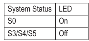
- PLED (Power LED, Yellow):
![]()
Connects to the power status indicator on the chassis front panel. The LED is on when the system is operating. The LED is off when the system is in S3/S4 sleep state or powered off (S5).
- PW (Power Switch, Red):
Connects to the power switch on the chassis front panel. You may configure the way to turn off your system using the power switch (refer to Chapter "BIOS Setup," "Chipset," for more information). - HD (Hard Drive Activity LED, Blue):
Connects to the hard drive activity LED on the chassis front panel. The LED is on when the hard drive is reading or writing data. - RES (Reset Switch, Green):
Connects to the reset switch on the chassis front panel. Press the reset switch to restart the computer if the computer freezes and fails to perform a normal restart. - NC (Purple):
No connection.
The front panel design may differ by chassis. A front panel module mainly consists of power switch, reset switch, power LED, hard drive activity LED and etc. When connecting your chassis front panel module to this header, make sure the wire assignments and the pin assignments are matched correctly.
- F_AUDIO (Front Panel Audio Header)
The front panel audio header supports Intel High Definition audio (HD) and AC'97 audio. You may connect your chassis front panel audio module to this header. Make sure the wire assignments of the module connector match the pin assignments of the motherboard header. Incorrect connection between the module connector and the motherboard header will make the device unable to work or even damage it.
")
")
- The front panel audio header supports HD audio by default.
- Audio signals will be present on both of the front and back panel audio connections simultaneously.
- Some chassis provide a front panel audio module that has separated connectors on each wire instead of a single plug. For information about connecting the front panel audio module that has different wire assignments, please contact the chassis manufacturer.
- BAT (Battery)
The battery provides power to keep the values (such as BIOS configurations, date, and time information) in the CMOS when the computer is turned off. Replace the battery when the battery voltage drops to a low level, or the CMOS values may not be accurate or may be lost.
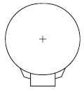
You may clear the CMOS values by removing the battery cable:
- Turn off your computer and unplug the power cord.
- Unplug the the battery cable from the battery cable header and wait for one minute.
- Plug in the battery cable.
- Plug in the power cord and restart your computer.
- Always turn off your computer and unplug the power cord before replacing the battery.
- Replace the battery with an equivalent one. Danger of explosion if the battery is replaced with an incorrect model.
- Contact the place of purchase or local dealer if you are not able to replace the battery by yourself or uncertain about the battery model.
- When installing the battery, note the orientation of the positive side (+) and the negative side (-) of the battery (the positive side should face up).
- Used batteries must be handled in accordance with local environmental regulations.
- F_USB30 (USB 3.1 Gen 1 Header)
The header conforms to USB 3.1 Gen 1 and USB 2.0 specification and can provide two USB ports. For purchasing the optional 3.5" front panel that provides two USB 3.1 Gen 1 ports, please contact the local dealer.
")
")
- F_USB1/F_USB2 (USB 2.0/1.1 Headers)
The headers conform to USB 2.0/1.1 specification. Each USB header can provide two USB ports via an optional USB bracket. For purchasing the optional USB bracket, please contact the local dealer.
")
")
- Do not plug the IEEE 1394 bracket (2x5-pin) cable into the USB header.
- Prior to installing the USB bracket, be sure to turn off your computer and unplug the power cord from the power outlet to prevent damage to the USB bracket.
- LPT (Parallel Port Header)
The LPT header can provide one parallel port via an optional LPT port cable. For purchasing the optional LPT port cable, please contact the local dealer.
")
")
- TPM (Trusted Platform Module Header)
You may connect a TPM (Trusted Platform Module) to this header.
")
")
- CLR_CMOS (Clear CMOS Jumper)
Use this jumper to clear the BIOS configuration and reset the CMOS values to factory defaults. To clear the CMOS values, use a metal object like a screwdriver to touch the two pins for a few seconds.
![]()
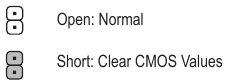
- Always turn off your computer and unplug the power cord from the power outlet before clearing the CMOS values.
- After system restart, go to BIOS Setup to load factory defaults (select Load Optimized Defaults) or manually configure the BIOS settings (refer to Chapter "BIOS Setup," for BIOS configurations).
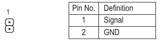
- CI (Chassis Intrusion Header)
This motherboard provides a chassis detection feature that detects if the chassis cover has been removed. This function requires a chassis with chassis intrusion detection design.
![]()
BIOS Setup
BIOS (Basic Input and Output System) records hardware parameters of the system in the CMOS on the motherboard. Its major functions include conducting the Power-On Self-Test (POST) during system startup, saving system parameters and loading operating system, etc. BIOS includes a BIOS Setup program that allows the user to modify basic system configuration settings or to activate certain system features. When the power is turned off, the battery on the motherboard supplies the necessary power to the CMOS to keep the configuration values in the CMOS. To access the BIOS Setup program, press the <Delete> key during the POST when the power is turned on. To upgrade the BIOS, use the GIGABYTE @BIOS utility, which is a Windows-based utility that searches and downloads the latest version of BIOS from the Internet and updates the BIOS.
- Because BIOS flashing is potentially risky, if you do not encounter problems using the current version of BIOS, it is recommended that you not flash the BIOS. To flash the BIOS, do it with caution. Inadequate BIOS flashing may result in system malfunction.
- It is recommended that you not alter the default settings (unless you need to) to prevent system instability or other unexpected results. Inadequately altering the settings may result in system's failure to boot. If this occurs, try to clear the CMOS values and reset the board to default values. (Refer to the "Restore Defaults" section in this chapter or introductions of the battery/clear CMOS jumper in Hardware Installation Chapter for how to clear the CMOS values.)
Main
Once you enter the BIOS Setup program, the Main Menu (as shown below) appears on the screen. Use arrow keys to move among the items and press <Enter> to accept or enter a sub-menu.
Main Menu Help
The on-screen description of a highlighted setup option is displayed on the bottom line of the Main Menu.
Submenu Help
While in a submenu, press <F1> to display a help screen (General Help) of function keys available for the menu. Press <Esc> to exit the help screen. Help for each item is in the Item Help block on the right side of the submenu. (Sample BIOS Version: F3a)
- When the system is not stable as usual, select the Load Optimized Defaults item to set your system to its defaults.
- The BIOS Setup menus described in this chapter are for reference only and may differ by BIOS version.


This section provides information on your motherboard model and BIOS version. You can also select the default language used by the BIOS and manually set the system time.
 System Language
Selects the default language used by the BIOS.
System Date
Sets the system date. The date format is week (read-only), month, date, and year. Use <Tab> to switch between the Month, Date, and Year fields and use the <+> or <-> key to set the desired value.
System Time
Sets the system time. The time format is hour, minute, and second. For example, 1 p.m. is 13:00:00. Use <Tab> to switch between the Hour, Minute, and Second fields and use the <+> or <-> key to set the desired value.
Access Level
Displays the current access level depending on the type of password protection used. (If no password is set, the default will display as Administrator.) The Administrator level allows you to make changes to all BIOS settings; the User level only allows you to make changes to certain BIOS settings but not all.
Advanced

OnBoard LAN Controller (LAN1)
Enables or disables the onboard LAN function. (Default: Enabled) If you wish to install a 3rd party add-in network card instead of using the onboard LAN, set this item to Disabled.
OnBoard LAN Controller#2 (LAN2)
Enables or disables the onboard LAN function. (Default: Enabled) If you wish to install a 3rd party add-in network card instead of using the onboard LAN, set this item to Disabled.
Power Loading
Enables or disables dummy load. When the power supply is at low load, a self-protection will activate causing it to shutdown or fail. If this occurs, please set to Enabled. Auto lets the BIOS automatically configure this setting. (Default: Auto)
Soft-Off by PWR-BTTN
Configures the way to turn off the computer in MS-DOS mode using the power button.
 Instant-Off Press the power button and then the system will be turned off instantly. (Default)
Delay 4 Sec. Press and hold the power button for 4 seconds to turn off the system. If the power button is pressed for less than 4 seconds, the system will enter suspend mode.
Primary Display
Specifies the first initiation of the monitor display from the installed PCI graphics card or the onboard graphics.
IGD Sets the onboard graphics as the first display. (Default)
PCI Sets the graphics card on the PCI Slot as the first display.
PCIE VGA Workaround
Allows you to increase the compatibility of the PCI graphics card. (Default: Disabled)
ErP
Determines whether to let the system consume least power in S5 (shutdown) state. (Default: Disabled) Note: When this item is set to Enabled, the following functions will become unavailable: Resume by Alarm, PME event wake up, power on by mouse, power on by keyboard, and wake on LAN.
 Realtek PCIe GBE Family Controller (LAN1)
This sub-menu provides information on LAN configuration and related configuration options.
Realtek PCIe GBE Family Controller (LAN2)
This sub-menu provides information on LAN configuration and related configuration options.
Trusted Computing
Enables or disables Trusted Platform Module (TPM).
IT8686 Super IO Configuration
This section provides information on the super I/O chip and allows you to configure the serial port and parallel port.
Hardware Monitor
CPU Temperature/System Temperature
Displays current CPU/system temperature.
CPU/System Fan Speed
Displays current CPU/system fan speeds.
VCCGI/VCC3/+12V/VCC/Vnn/DDR_VDDQ
Displays the current system voltages.
SIO Misc Functions
AC BACK
Determines the state of the system after the return of power from an AC power loss.
Memory The system returns to its last known awake state upon the return of the AC power.
Always On The system is turned on upon the return of the AC power.
Always Off The system stays off upon the return of the AC power. (Default)
Case Open
Displays the detection status of the chassis intrusion detection device attached to the motherboard CI header. If the system chassis cover is removed, this field will show "Open", otherwise it will show "Close." To clear the chassis intrusion status record, set Reset Case Open Status to Enabled, save the settings to the CMOS, and then restart your system.
Reset Case Open Status
Disabled Keeps or clears the record of previous chassis intrusion status. (Default)
Enabled Clears the record of previous chassis intrusion status and the Case Open field will show "No" at next boot.
Case intrusion Prompt
Allows you to determine whether to display chassis intrusion notification at system startup. (Default: Disabled)
CPU Configuration
CPU Power Management
EIST
Enables or disables Enhanced Intel ® Speed Step Technology (EIST). Depending on CPU loading, Intel® EIST technology can dynamically and effectively lower the CPU voltage and core frequency to decrease average power consumption and heat production. Auto lets the BIOS automatically configure this setting. (Default: Enabled)
Turbo Mode
Allows you to determine whether to enable the Intel ® CPU Turbo Boost technology. (Default: Enabled)
C-States
Enables or disables support for C-States. (Default: Enabled)
Enhanced C-states
Allows you to determine whether to let the CPU enter C states. When enabled, the CPU core frequency will be reduced during system halt state to decrease power consumption. This item is configurable only when C-States is enabled. (Default: Enabled)
Active Processor Cores
Allows you to select the number of CPU cores to enable. (Default: Disabled)
Intel Virtualization Technology
Enables or disables Intel ® Virtualization Technology. Virtualization enhanced by Intel ® Virtualization Technology will allow a platform to run multiple operating systems and applications in independent partitions. With virtualization, one computer system can function as multiple virtual systems. (Default: Enabled)
VT-d
Enables or disables Intel ® Virtualization Technology for Directed I/O. (Default: Disabled)
Network Stack Configuration
Network Stack
Disables or enables booting from the network to install a GPT format OS, such as installing the OS from the Windows Deployment Services server. (Default: Disabled)
Ipv4 PXE Support
Enables or disables IPv4 PXE Support. This item is configurable only when Network Stack is enabled.
Ipv4 HTTP Support
Enables or disables HTTP boot support for IPv4. This item is configurable only when Network Stack is enabled.
Ipv6 PXE Support
Enables or disables IPv6 PXE Support. This item is configurable only when Network Stack is enabled.
Ipv6 HTTP Support
Enables or disables HTTP boot support for IPv6. This item is configurable only when Network Stack is enabled.
PXE boot wait time
Allows you to configure how long to wait before you can press <Esc> to abort the PXE boot. This item is configurable only when Network Stack is enabled. (Default: 0)
Media detect count
Allows you to set the number of times to check the presence of media. This item is configurable only when Network Stack is enabled. (Default: 1)
CSM Configuration
CSM Support
Enables or disables UEFI CSM (Compatibility Support Module) to support a legacy PC boot process.
Enabled Enables UEFI CSM. (Default)
Disabled Disables UEFI CSM and supports UEFI BIOS boot process only.
Network
Allows you to select whether to enable the UEFI or legacy option ROM for the LAN controller.
Do not launch Disables option ROM.
UEFI Enables UEFI option ROM only. (Default)
Legacy Enables legacy option ROM only.
This item is configurable only when CSM Support is set to Enabled.
Storage
Allows you to select whether to enable the UEFI or legacy option ROM for the storage device controller.
Do not launch Disables option ROM.
UEFI Enables UEFI option ROM only. (Default)
Legacy Enables legacy option ROM only.
This item is configurable only when CSM Support is set to Enabled.
Video
Allows you to select whether to enable the UEFI or legacy option ROM for the graphics controller.
Do not launch Disables option ROM.
UEFI Enables UEFI option ROM only. (Default)
Legacy Enables legacy option ROM only.
This item is configurable only when CSM Support is set to Enabled.
Other PCI devices
Allows you to select whether to enable the UEFI or Legacy option ROM for the PCI device controller other than the LAN, storage device, and graphics controllers.
Do not launch Disables option ROM.
UEFI Enables UEFI option ROM only. (Default)
Legacy Enables legacy option ROM only.
This item is configurable only when CSM Support is set to Enabled.
USB Configuration
Onboard USB Feature
Enables or disables the onboard USB function. (Default: Enabled)
Legacy USB Support
Allows USB keyboard/mouse to be used in MS-DOS. (Default: Enabled)
XHCI Hand-off
Determines whether to enable XHCI Hand-off feature for an operating system without XHCI Hand-off support. (Default: Enabled)
USB Mass Storage Driver Support
Enables or disables support for USB storage devices. (Default: Enabled)
USB Storage Devices
Displays a list of connected USB mass storage devices. This item appears only when a USB storage device is installed.
Security

Setup Administrator Password
Allows you to configure an administrator password. Press <Enter> on this item, type the password, and then press <Enter>. You will be requested to confirm the password. Type the password again and press <Enter>. You must enter the administrator password (or user password) at system startup and when entering BIOS Setup. Differing from the user password, the administrator password allows you to make changes to all BIOS settings.
User Password
Allows you to configure a user password. Press <Enter> on this item, type the password, and then press <Enter>. You will be requested to confirm the password. Type the password again and press <Enter>. You must enter the administrator password (or user password) at system startup and when entering BIOS Setup. However, the user password only allows you to make changes to certain BIOS settings but not all. To cancel the password, press <Enter> on the password item and when requested for the password, enter the correct one first. When prompted for a new password, press <Enter> without entering any password. Press <Enter> again when prompted to confirm. NOTE: Before setting the User Password, be sure to set the Administrator Password first.
HDD Security Configuration
Displays a list of connected hard drives and allows you to set a password for a specific hard drive. This item appears only when a hard drive is installed.
Secure Boot
System Mode
Displays the current system mode.
Secure Boot
Displays the current secure boot state.
Vendor Keys
Displays the vendor keys.
Attempt Secure Boot
Enables or disables the secure boot function. Secure Boot requires all the applications that are running during the booting process to be pre-signed with valid digital certificates. This way, the system knows all the files being loaded before Windows 8 loads and gets to the login screen have not been tampered with. (Default: Disabled)
Secure Boot Mode
Allows you to configure the secure boot mode. (Default: Customized)
Key Management
This section provides you with configuration options for secure boot key management.
Boot

Setup Prompt Timeout
Allows you to configure the number of seconds to stay in BIOS setup prompt screen. (Default: 1)
Bootup NumLock State
Enables or disables Numlock feature on the numeric keypad of the keyboard after the POST. (Default: On)
Full Screen LOGO Show
Allows you to determine whether to display the GIGABYTE Logo at system startup. Disabled skips the GIGABYTE Logo when the system starts up. (Default: Enabled)
Boot Option #1/2/3
Specifies the overall boot order from the available devices. For example, you can set hard drive as the first priority (Boot Option #1) and DVD ROM drive as the second priority (Boot Option #2). The list only displays the device with the highest priority for a specific type. For example, only hard drive defined as the first priority on the Hard Drive BBS Priorities submenu will be presented here.
Removable storage devices that support GPT format will be prefixed with "UEFI:" string on the boot device list. To boot from an operating system that supports GPT partitioning, select the device prefixed with "UEFI:" string.
Or if you want to install an operating system that supports GPT partitioning such as Windows 7 64-bit, select the optical drive that contains the Windows 7 64-bit installation disk and is prefixed with "UEFI:" string.
Hard Drive/CD/DVD ROM Drive/Floppy Drive/Network Device BBS Priorities
Specifies the boot order for a specific device type, such as hard drives, optical drives, floppy disk drives, and devices that support Boot from LAN function, etc. Press <Enter> on this item to enter the submenu that presents the devices of the same type that are connected. This item is present only if at least one device for this type is installed.
New Boot Option Policy
Allows you to determine whether to change the boot order when a new device is added.
Default Keeps the previous boot order settings. (Default)
Place First Set the newly added device as the first boot device.
Place Last Set the newly added device as the last boot device.
Save & Exit

Save Changes and Exit
Press <Enter> on this item and select Yes. This saves the changes to the CMOS and exits the BIOS Setup program. Select No or press <Esc> to return to the BIOS Setup Main Menu.
Discard Changes and Exit
Press <Enter> on this item and select Yes. This exits the BIOS Setup without saving the changes made in BIOS Setup to the CMOS. Select No or press <Esc> to return to the BIOS Setup Main Menu.
Save Changes
Press <Enter> on this item and select Yes to save the changes to the CMOS. Select No or press <Esc> to return to the BIOS Setup Main Menu.
Discard Changes
Press <Enter> on this item and select Yes to cancel the BIOS changes. Select No or press <Esc> to return to the BIOS Setup Main Menu.
Restore Defaults
Press <Enter> on this item and select Yes to load the BIOS factory default settings. The BIOS defaults settings help the system to operate in optimum state. Always load the Optimized defaults after updating the BIOS or after clearing the CMOS values.
Save as User Defaults
Save to current BIOS settings as user-defined default settings.
Restore User Defaults
Load the user-define default settings for all BIOS options.
Boot Override
Allows you to select a device to boot immediately. Press <Enter> on the device you select and select Yes to confirm. Your system will restart automatically and boot from that device.
Launch EFI Shell from filesystem device
Allows you to launch the EFI Shell application (shell.efi) from one of the available filesystem devices. Press <Enter> on this option and the system will restart to the EFI Shell screen automatically.
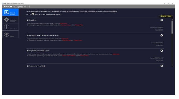
Drivers Installation
- Before installing the drivers, first install the operating system. (The following instructions use Windows 10 as the example operating system.)
- After installing the operating system, insert the motherboard driver disk into your optical drive. Click on the message "Tap to choose what happens with this disc" on the top-right corner of the screen and select "Run Run.exe." (Or go to My Computer, double-click the optical drive and execute the Run.exe program.)
"Xpress Install" will automatically scan your system and then list all of the drivers that are recommended to install. You can click the Xpress Install button and "Xpress Install" will install all of the selected drivers. Or click the arrow  icon to individually install the drivers you need.
Contact Us
GIGA-BYTE TECHNOLOGY CO., LTD.
Address: No.6, Baoqiang Rd., Xindian Dist., New Taipei City 231, Taiwan
TEL: +886-2-8912-4000, FAX: +886-2-8912-4005
Tech. and Non-Tech. Support (Sales/Marketing): http://esupport.gigabyte.com
WEB address (English): http://www.gigabyte.com
WEB address (Chinese): http://www.gigabyte.tw
- GIGABYTE eSupport
To submit a technical or non-technical (Sales/Marketing) question, please link to: http://esupport.gigabyte.com
![]()
Documents / Resources
References
Download manual
Here you can download full pdf version of manual, it may contain additional safety instructions, warranty information, FCC rules, etc.
Advertisement
Thank you! Your question has been received!


Need Assistance?
Do you have a question about the GA-J3455N-D3H that isn't answered in the manual? Leave your question here.