Table of Contents
Advertisement
Available languages
Available languages
Quick Links
1111 W. 35th Street Chicago, IL 60609 USA
Customer Support: (773) 869-1234
Safety
IMPORTANT SAFETY INSTRUCTIONS.
SAVE THESE INSTRUCTIONS.
This manual contains instructions and warnings that should be followed during the
installation and operation of all Tripp Lite Console Component Power Centers.
Failure to heed these warnings will void your warranty.
• The Console Component Power Center features an internal protection that will
disconnect the surge-protective component at the end of its useful life but will
maintain power to the load—now unprotected.
• Do not connect the Console Component Power Center to an ungrounded outlet. Do
not use with 2-wire extension cords or adapters. Do not plug extension cords into
the Console Component Power Center.
Features
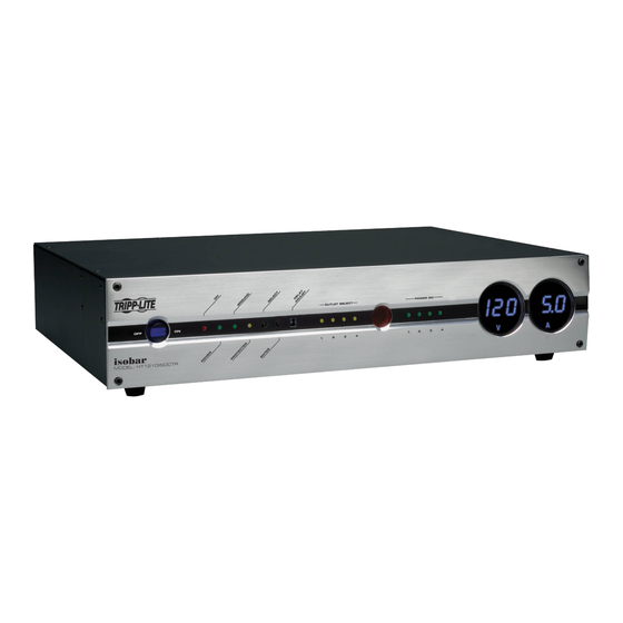
MODEL: HT1210ISOCTR
Front Panel
A
Illuminated "ON/OFF" Power Switch: turns power on and off at all of the
outlets.
B
"ON" LED: indicates that AC power is available at the Console Component
Power Center's outlets. This LED will illuminate when the Power Switch is set to
"ON".
"POWER" LED: indicates AC power is available at the wall outlet.
C
"GROUND" LED: indicates wall outlet is grounded and surge protection can
D
properly function.
"PROTECTED" LED: indicates the surge suppression components are intact
E
and providing complete protection against surges. If this LED does not illuminate,
some of the surge suppression components are not functioning, and the unit should
be replaced. Call Tripp Lite Customer Support at (773) 869-1234.
"SELECT" Switch: selects controllable IR outlets (labeled "IR1", "IR2", "IR3"
F
and "IR4" on the rear panel of the Console Component Power Center) to be turned
on or off using the "ENTER" Switch. See "IR Outlet Control" in the "Optional
Installation" section for setting procedure.
"ENTER" Switch: turns controllable IR outlets on or off (after they have first
G
been selected using the "SELECT" Switch). See "IR Outlet Control" in the
"Optional Installation" section for setting procedure.
"DELAY/ADJUST" DIP Switches: select the delay interval (0, 1, 10 or 30
H
seconds) when turning on or off multiple IR outlets in a sequence using a remote.
See "IR Outlet Control" in the "Optional Installation" section for setting
procedure.
"OUTLET SELECT" LEDs: indicate which controllable IR outlets (labeled
I
"IR1", "IR2", "IR3" and "IR4" on the rear panel of the Console Component
Power Center) have been selected using the "SELECT" Switch. Each LED will
flash when its corresponding IR outlet has been selected. Each LED will
illuminate continuously when power has been turned on at the outlet.
www.tripplite.com
Español: p.5
A
B
C
D
E
F
G
H
isobar
®
Console Component
Power Center with
Digital IR Remote
Model: HT1210ISOCTR
Français: p.9
• The Console Component Power Center is designed for indoor use only. Install the
Console Component Power Center away from heat-emitting appliances such as
radiators or heat registers. Do not install where excessive moisture is present.
• Never install electrical, telephone, network or coaxial wiring during a lightning
storm.
• Do not drill into any part of the housing or open the housing for any reason. There
are no user-serviceable parts inside.
J
I
K
Front Panel
J
"POWER ON" LEDs: indicate which controllable IR outlets have been turned
ON using the "ENTER" Switch. Each LED will flash when its corresponding IR
outlet has been selected. Each LED will illuminate continuously when power has
been turned on at the outlet.
K
Infrared (IR) Sensor: is for use with either the included IR remote or a universal
learning IR remote (user-supplied)* to control IR outlets. Program the outlets to
turn on or off individually or in a sequence. If the sensor is covered, a remote IR
sensor (user-supplied) can be connected to the IR sensor input on the rear panel of
the Console Component Power Center.
* The user-supplied remote must be a universal learning type to work with the included remote.
L
"Input Voltage" Digital LED Display: clearly shows voltage variations of
incoming utility power. The Console Component Power Center can alert you to
abnormal voltage, but cannot regulate it. If persistent low or high voltage
conditions continually affect equipment performance, consider purchasing a
Tripp Lite UPS system or line conditioner.
M
"Current Usage" LED Display: allows you to get the maximum use from your
Console Component Power Center by showing you the total amperage load of all
of your connected components. CAUTION: the total amperage capacity of the
Console Component Power Center is 15 amps. Any amperage loads that exceed
15 amps will cause the circuit breaker to trip. Action should be taken to reduce
connected load and reset the circuit breaker.
N
Rackmount Hardware: allows 2U mounting in standard sized racks.
O
Removeable Console Feet: allow placement on a shelf as a console component
within a system. Unscrew feet prior to rackmounting the Console Component
Power Center.
1
Owner's Manual
O
N
L
M
Advertisement
Table of Contents

Related Manuals for Tripp Lite isobar HT1210ISOCTR


Summary of Contents for Tripp Lite isobar HT1210ISOCTR
- Page 1 SAVE THESE INSTRUCTIONS. This manual contains instructions and warnings that should be followed during the installation and operation of all Tripp Lite Console Component Power Centers. Failure to heed these warnings will void your warranty. • The Console Component Power Center features an internal protection that will disconnect the surge-protective component at the end of its useful life but will maintain power to the load—now unprotected.
-
Page 2: Installation
Audible Alarm: immediately alerts you to damaged internal protection circuitry. If this occurs, contact Tripp Lite Customer Support. STEP 5) Connect Your Equipment to the Console Component Power Center's AC Outlets: Plug your equipment's power cords (including 2-wire devices) into the Console Component Power Center's AC outlets. -
Page 3: Optional Installation
Optional Installation Tel/Modem, Ethernet and Coaxial Connections Connect Your Equipment to the Console Component Power Center's Tel/Modem Jacks: Connect a phone cable from the wall jack directly to the Console Component Power Center's RJ-style phone jack labeled “IN.” Connect a phone cable from the Console Component Power Center's RJ-style phone jack labeled "OUT"... -
Page 4: Troubleshooting
Troubleshooting Before calling Tripp Lite for technical assistance, try the possible solutions to common problems listed below. If you still require assistance, call Tripp Lite Customer Service at (773) 869-1234. Problem Possible Solutions No AC output power available at Check Connections: Ensure the power cord is properly connected to a live 120V AC wall outlet. -
Page 5: Manual Del Propietario
Si este LED no se ilumina, algunos de los componentes del sistema de supresión de sobretensiones no están funcionando y la unidad debe ser reemplazada. Llame a Soporte al cliente de Tripp Lite al (773) 869-1234. Interruptor “SELECT”: Selecciona las salidas IR controlables (rotuladas “IR1”, “IR2”, “IR3”... -
Page 6: Instalación
Alarma Audible: Le alerta inmediatamente si existe algún circuito de protección interna dañado. En este caso, contacte con el Soporte al cliente de Tripp Lite. de consola esté conectado a una salida con energía de 120 V CA y cuando el interruptor de alimentación del Centro de energía para componente de consola. -
Page 7: Instalación Opcional
RJ del Centro de energía para componente de consola etiquetado “OUT” [SALIDA] directamente al dispositivo que va a proteger. Los modelos HT1210ISOCTR presentan dos conectores “OUT”; pueden usarse uno sólo o ambos, pero la protección es para un dispositivo o dispositivos que compartan una sola línea. -
Page 8: Solución De Problemas
Solución de problemas Antes de llamar a Tripp Lite para ayuda técnica, revise las soluciones posibles para problemas comunes a continuación. Si requiere de ayuda, llame al Servicio al cliente de Tripp Lite al (773) 869-1234. Problema Soluciones posibles No hay potencia de salida de CA Verifique las conexiones: Asegúrese que el cordón de alimentación esté... -
Page 9: Manuel Du Propriétaire
Ce manuel contient des instructions et des mises en garde qu'il faut suivre pendant l'installation et l'utilisation de tous les Distributeurs d'alimentation électrique en élément de console de Tripp Lite. Le non respect de ces mises en garde annulera votre garantie. - Page 10 électrique en élément de console. Alarme sonore : Elle vous alerte immédiatement si les circuits de protection interne sont endommagés. Dans ce cas, communiquer avec l'assistance à la clientèle de Tripp Lite. ÉTAPE 5) Connecter votre équipement aux prises du Distributeur d'alimentation électrique en élément de console : Brancher les cordons d"alimentation de votre...
-
Page 11: Installation Optionnelle
Distributeur d'alimentation électrique en élément de console à l'appareil à protéger. Les modèles HT1210ISOCTR disposent de deux prises « OUT »; l'une ou l'autre de ces prises peut être utilisée, mais la protection n'existe que pour un ou des appareils ne partageant qu'une ligne. -
Page 12: Dépannage
Dépannage Avant d'appeler Tripp Lite pour de l'assistance technique, essayer les solutions possibles aux problèmes courants suivants: Si vous avez toujours besoin assistance, appeler le service à la clientèle de Tripp Lite au (773) 869-1234. Problème Solutions possibles Pas de courant CA aux prises.