Chapters
Table of Contents

Related Manuals for Fisher & Paykel DCS BGB48-BQAR


Summary of Contents for Fisher & Paykel DCS BGB48-BQAR
- Page 1 Professional grill Installation instructions 36/48” BGB models User guide Le gril professionnel Instructions d’installation Modèles 36/48po BGB Guide d’utilisation US CA...
- Page 3 A MESSAGE TO OUR CUSTOMERS Thank you for selecting this DCS Professional “BGB” Series Grill. Because of these appliances’ unique features we have developed this manual. It contains valuable information on how to properly install, operate and maintain your new appliance for years of safe and enjoyable cooking. To help serve you better, please fill out and submit your Product Registration by visiting our website at www.dcsappliances.com and selecting “Customer Care”...
-
Page 4: Table Of Contents
TABLE OF CONTENTS SAFETY PRACTICES & PRECAUTIONS GRILL MODELS INSTALLATION Locating Grill / Built-in Clearances Built-in Construction Details 10-11 Gas Hook-up 12-15 Leak Testing Burner Adjustment Radiant Assembly Installer Checklist USING THE GRILL Lighting Instructions Grilling 21-22 USING THE SMOKER SYSTEM USING THE ROTISSERIE 24-27 CARE &... -
Page 5: Safety Practices & Precautions
SAFETY PRACTICES & PRECAUTIONS IMPORTANT SAFETY NOTICE! Certain Liquid Propane dealers may fill liquid propane cylinders for use in the grill beyond cylinder filling capacity. This “Overfilling” may create a dangerous condition. “Overfilled” tanks can build up excess pressure. As a safety device, the tank pressure relief valve will vent propane gas vapor to relieve this excess pressure. - Page 6 SAFETY PRACTICES & PRECAUTIONS ■ After a period of storage or non-use (such as over the winter), the gas grill should be checked for gas leaks, dete- rioration, proper assembly, and burner obstructions before using. ■ Never let clothing, pot holders or other flammable materials come in contact with or get too close to any grate, burner or hot surface until it has cooled.
- Page 7 SAFETY PRACTICES & PRECAUTIONS ■ When using the side burners always use flat bottomed pans which are large enough to cover the side burner. Adjust the flame so that it heats only the bottom of the pan to avoid ignition of clothing. Position handles inward away from open edges of the unit to avoid burns associated with unintentional spillovers.
-
Page 8: Grill Models
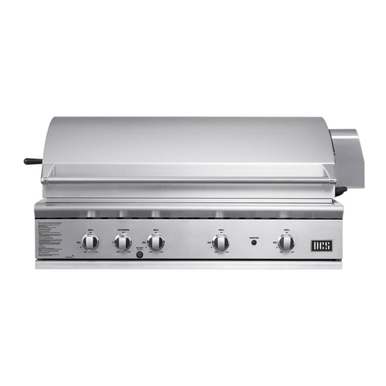
GRILL MODELS IGN ITION IGN ITION BGB48-BQAR BGB48-BQR BGB36-BQAR... -
Page 9: Installation
INSTALLATION LOCATING GRILL/BUILT-IN CLEARANCES Important! Shipping Brackets Before installation, remove shipping brackets from the grill. To do so, loosen the 4 screws on the bottom sides of the grill which hold the brackets to the grill. Slide the shipping brackets off and retighten the screws. - Page 10 INSTALLATION LOCATING GRILL/BUILT-IN CLEARANCES Clearances to Non-Combustible Construction*: A minimum of 3” clearance from the back of the grill to non-combustible construction is required for the purpose of allowing the lid to open fully. It is desirable to allow at least 6” rear and side clearance to non-combustible construction above the cooking surface for counter space.
- Page 11 INSTALLATION LOCATING GRILL/BUILT-IN CLEARANCES Clearances to Combustible Construction** grill exhaust 26-1/2" 12" min. (to combustible 12" min. 12" min. construction) rotisserie motor 24-1/4" Bottom of 10-1/2" support flange 10 " 2" 22" 25-1/2" FIG. 04 ** DEFINITION OF COMBUSTIBLE MATERIAL - Any materials of a building structure or decorative structure made of wood, compressed paper, plant fibers, vinyl/plastic or other materials that are capable of transferring heat or being ignited and burned.
-
Page 12: Built-In Construction Details
INSTALLATION BUILT–IN CONSTRUCTION DETAILS grill exhaust 3" (to non-combustible construction / minimum lid clearance) 12" (to combustible 13-3/4" construction) Bottom of support flange 10" 2" 22" 1-1/2" 25-1/2" Standard layout for non-combustible enclosure: Layout for insulated jacket only - combustible enclosure: NOTE: If using a backguard NOTE: If using a backguard apron or rear wall, locate... - Page 13 INSTALLATION BUILT–IN CONSTRUCTION DETAILS Access Drawers Access Doors - Cutout dimensions Cutout dimensions Vent* Vent* Vent* 90º Cutout for Access Doors FIG. 06 FIG. 07 º NOTE: The cutout of each corner should be 90 º angle in order for the access NOTE: The cutout of each corner should be 90 angle in order for the access doors to fit properly.
-
Page 14: Gas Hook-Up
INSTALLATION GAS HOOK-UP GAS REQUIREMENTS Verify the type of gas supply to be used, either natural or LP, and make sure the marking on the appliance rating plate agrees with that of the supply. The rating plate is located underneath the unit bottom. Never connect an unregulated gas line to the appliance. - Page 15 INSTALLATION GAS HOOK-UP Connection: 1/2” NPT male with a 3/8” Flare adapter (included). LP Hose with a quick disconnect and fittings are included. Operating pressure: 11.0” W.C. Note: All gas piping and connectors must conform to the Standard for Connectors for Outdoor Gas Appliances and Manufactured Homes, ANSI Z21.75/CSA 6.27.
- Page 16 INSTALLATION GAS HOOK-UP LP TANK RESTRAINT FOR BUILT-IN INSTALLATION If the grill is to be installed in a Built-in application, then the grill must be installed in accordance with the Built–in installation guidelines. The gas connector must comply with the Standard for Connectors for Outdoor Gas Appliances & Manufactures Homes, ANSI Z21.75/ CSA 6.27.
- Page 17 INSTALLATION GAS HOOK-UP STEP 1 Place the tank restraint in the island (Fig. 11). STEP 2 Locate the tank restraint in the island within the recommended area (Fig. 10 and 12). STEP 3 Once located, secure to the bottom of the island using all eight hole locations provided on the restraint.
-
Page 18: Leak Testing
INSTALLATION LEAK TESTING GENERAL: Although all gas connections on the grill are leak tested at the factory prior to shipment, a complete gas tightness check must be performed at the installation site due to possible mishandling in shipment, or excessive pressure unknowingly being applied to the unit. -
Page 19: Burner Adjustment
INSTALLATION BURNER ADJUSTMENT GRILL BURNER AIR ADJUSTMENT: Each grill burner is tested and adjusted at the factory prior to shipment; however, variations in the local gas supply or a conversion from one gas to another may make it necessary to adjust the burners. The flames of the burners (except the rotisserie burner) should be visually checked and compared to that of the drawing in Fig.18. -
Page 20: Radiant Assembly
INSTALLATION RADIANT ASSEMBLY RADIANT ASSSEMBLY INSTALLATION: 1. Unpack ceramic rods and remove radiant (Fig. 21) from the unit. 2. Unlock radiant end cap by pushing it up with two fingers (Fig. 22). 3. Place 18 ceramic rods on the radiant (Fig. 23). 4. -
Page 21: Installer Checklist
INSTALLATION INSTALLER CHECKLIST ❏ Specified clearances main- ❏ Each burner lights satis- ❏ Unit tested and free of tained to combustibles. factorily, individually or leaks. with adjacent burner lit. ❏ Verified proper enclosure ❏ User informed of gas ❏ Air shutters adjusted. ventilation. -
Page 22: Using The Grill Lighting Instructions
USING THE GRILL LIGHTING INSTRUCTIONS TO LIGHT THE GRILL BURNER: Open the grill lid and/or remove the top grate cover from side burner (for 48BQR) before lighting. Turn all knobs to “OFF”. Turn the main gas supply on slowly. If you smell gas, shut off gas supply and call for service. Push and hold the ignition button, turn the selected burner knob to “SEAR”. -
Page 23: Grilling
USING THE GRILL GRILLING GRILL: Each grill section consists of a large stainless steel burner, stainless steel heat baffles, a series of ceramic rods encased in a stainless steel radiant, and a stainless steel heat retaining grate. Each burner is rated at 25,000 Btu/hr. Below the burners there is a stain- less steel heat baffle which reflects usable heat upward into the cooking area and reduces temperatures of the drip pan below. - Page 24 USING THE GRILL GRILLING (Continued) the cooking time. 1. Check to be certain the drip pan and grease tray are in place. 2. Light the grill burners using the instructions on page 20. 3. Preheat the grill for 5 to 10 minutes. Once you have verified the burners are lit, put the lid down to preheat. 4.
-
Page 25: Using The Smoker System
USING THE SMOKER SYSTEM The smoker system on each grill consists of a stainless steel slide out tray which is positioned above a 3,500 Btu/hr burner. The burner is controlled by a precision brass valve which is capable of being turned down to very low heat levels. -
Page 26: Using The Rotisserie
USING THE ROTISSERIE The grill rotisserie system is designed to cook items from the back using infrared heat. The location of the burner allows the placement of the rotisserie basting pan (included) beneath the food to collect juices and drippings for basting and gravy. To flavor the contents of the basting pan, you can add herbs, onion, garlic, or spices. - Page 27 USING THE ROTISSERIE WARNING! Never have the grill burners (bottom burners) on during Rotisserie cooking. It will burn your meat and make it very dry. Use only one section at a time, grill or rotisserie. PREPARATION Recommended: Dental floss or butcher string, scissors, broiler pan (bottom only), pliers, instant read thermometer, foil, and hot pads.
- Page 28 USING THE ROTISSERIE TO LIGHT THE ROTISSERIE BURNER BEFORE COOKING: The location of the rotisserie burner makes it more susceptible to strong wind conditions, more so than the protected grill burners. For this reason you should avoid operating the rotisserie during windy conditions. As an added safety feature we’ve equipped the burner with an automatic safety valve which will not allow gas to flow to the rotisserie burner unless the following conditions are present with the knob on: 1.
- Page 29 USING THE ROTISSERIE COOKING ON ROTISSERIE 1. Place prepared rod into motor, lay across to other side in groove (Fig.39). 2. Verify placement as shown in Fig. 40. 3. Ignite burner, start rotisserie motor, and keep on rotisserie valve on “high” for cooking all meats on the rotisserie. 4.
-
Page 30: Care & Maintenance
CARE AND MAINTENANCE BATTERY REPLACEMENT: 1. Remove drip pan. 2. Open cart door (on cart model only). 3. Pull battery downwards (This may require use of pliers). 4. Re-install upward and push to snap - Fig. 43. (Polarity is shown in Fig. 44). Note: FIG. - Page 31 CARE AND MAINTENANCE STAINLESS STEEL: The grill is made from non-rusting and non-magnetic stainless steel. After initial usage, areas of the grill may dis- color from the intense heat given off by the burners, this is normal. There are many different stainless steel clean- ers available.
- Page 32 CARE AND MAINTENANCE Fig. 48 Note: When replacing grill and/or smoker burners, or orifices following cleaning, confirm orifice penetration into burner as shown in Fig. 48 Be careful not to upset the air shutters’ original posi- tion (unless readjusting). Lower the rear of the burner into the cutouts on the support channel at the rear of the burner box.
-
Page 33: Troubleshooting
TROUBLESHOOTING BEFORE CALLING FOR SERVICE: If the grill does not function properly, use the following checklist before contacting your dealer for service. You may save the cost of a service call. Troubleshooting is for general purposes only. If the problem persists and you feel you require service, contact your dealer or the nearest authorized agency to perform service. -
Page 34: Service
SERVICE HOW TO OBTAIN SERVICE: For warranty service, please contact your local service provider or DCS Customer Care at (888) 936-7872. Before you call, please have the following information ready: ■ Model Number (can be found on the inside, right side panel behind the drip pan handle. See page 19.) ■... -
Page 35: Warranty
WARRANTY LIMITED WARRANTY When you purchase a new DCS Grill by Fisher & Paykel, you automatically receive a One Year Limited Warranty covering parts and labor for the entire product, and a Five Year Comprehensive Warranty covering the radiant trays, radiant tray side rails and drip pans for servicing within the 48 mainland United States, Hawaii, Washington D.C. - Page 36 WARRANTY (continued) 5. Change the set-up of the Product. 6. Unauthorized modifications of the Product. 7. Noise or vibration that is considered normal, for example, drain/fan sounds, regeneration noises or user warning beeps. 8. Correcting damage caused by pests, for example, rats, cockroaches etc. Defects caused by factors other than: 1.
- Page 39 À L’INTENTION DE NOS CLIENTS Nous vous remercions d’avoir choisi ce gril de la série professionnelle « BGB » de DCS. Nous avons conçu ce Manuel pour expliquer les fonctions uniques de ces appareils. Ce manuel contient des informations extrêmement utiles sur la façon correcte de faire fonctionner votre nouvel appareil et d’en faire l’entretien.
- Page 40 TABLE DES MATIÈRES MESURES DE SÉCURITÉ ET DE PRÉCAUTION MODÈLES DE GRIL INSTALLATION Emplacement du gril et des dégagements 8-10 Détails d’une construction intégrée 11-12 Branchement du gaz 13-16 Test de détection des fuites Réglages des brûleurs Installation de l’ensemble du radiant Liste de contrôle de l’installateur UTILISATION DU GRIL Instructions d’allumage...
-
Page 41: Mesures De Sécurité Et De Précaution
MESURES DE SÉCURITÉ ET DE PRÉCAUTION IMPORTANTE CONSIGNE DE SÉCURITÉ! Certains fournisseurs de propane liquide peuvent remplir les bonbonnes de propane liquide du gril au-delà de leur capacité. Ce trop-plein peut créer une situation dangereuse. Une accumulation de pression peut effet se produire dans les bouteilles trop remplies. En tant que dispositif de sécurité, la soupape de décharge évacue les vapeurs de gaz propane afin de diminuer l’excédent de pression. - Page 42 MESURES DE SÉCURITÉ ET DE PRÉCAUTION ■ Ne rangez pas d’objets pouvant intéresser les enfants autour ou en dessous du gril, dans le chariot ou une en- ceinte de maçonnerie. Ne laissez jamais les enfants ramper à l’intérieur d’un chariot ou d’une enceinte. ■...
- Page 43 MESURES DE SÉCURITÉ ET DE PRÉCAUTION EMPLACEMENT DU GRIL Si le vent est un problème, FLUX D'ÉVENT DE SORTIE il faut ajouter ÉVACUATION DU GRIL Le vent qui frappe un coupe- le gril pendant son vent. Le coupe-vent utilisation, particu- 15 po min.
- Page 44 MESURES DE SÉCURITÉ ET DE PRÉCAUTION ■ Ayez un extincteur de classe ABC à portée de la main – ne tentez jamais d’éteindre un incendie de graisse avec de l’eau ou d’autres liquides. ■ Pour éviter toute brûlure lors de la cuisson, utilisez des outils de barbecue à manches longs. ■...
-
Page 45: Modèles De Gril
MODÈLES DE GRIL IGN ITION IGN ITION BGB48-BQAR BGB48-BQR BGB36-BQAR... -
Page 46: Installation
INSTALLATION EMPLACEMENT DU GRIL ET DES DÉGAGEMENTS Important! supports d’expédition Avant toute installation, retirez les supports d’expédition du gril. Pour ce faire, desserrer les 4 vis sur le dessous du gril qui maintiennent les supports au gril. Retirez les supports en les faisant glisser et resserrer les vis. - Page 47 INSTALLATION EMPLACEMENT DU GRIL ET DES DÉGAGEMENTS Important! Les raccords de gaz, le régulateur et le robinet d’arrêt fournis par l’installateur doivent être facilement acces- sibles. Espaces de dégagement pour une construction non combustible * Prévoyez une distance de 7,6 cm (3 po) minimum entre l’arrière du gril et la construction non combustible afin de pouvoir ouvrir le couvercle complètement.
- Page 48 INSTALLATION EMPLACEMENT DU GRIL ET DES DÉGAGEMENTS Espaces de dégagement pour une construction combustible ** évacuation du gril 30,5 cm/12 po 67,31 cm/26 1/2 po 30,5 cm/ 30,5 cm/ (dégagement 12 po min. avec une 12 po min. construction combustible) moteur de rôtissoire 61,28 cm/...
-
Page 49: Détails D'une Construction Intégrée
INSTALLATION DÉTAILS D’UNE CONSTRUCTION INTÉGRÉE évacuation du gril 7,6 cm/3 po (dégagement min. pour le couvercle avec une construction non combustible) 30,5 cm/12 po (dégagement avec une 34,93 cm/ construction combustible) 13 3/4 po Fond de la bride de soutien 24,5 cm/10 po 5,08 cm/ 55,88 cm/22 po... - Page 50 INSTALLATION DÉTAILS D’UNE CONSTRUCTION INTÉGRÉE LES TIROIRS - DIMENSIONS DES DECOUPES PORTES D’ACCÈS - DIMENSIONS DES DECOUPES Vent* Vent* Vent* 90º Découpe pour portes d’accès FIG. 07 FIG. 06 REMARQUE: La découpe de chaque coin doit être d’un angle REMARQUE: La découpe de chaque coin doit être d’un de 90 º...
-
Page 51: Branchement Du Gaz
INSTALLATION BRANCHEMENT DU GAZ EXIGENCES CONCERNANT LE GAZ Vérifiez le type de gaz à utiliser (gaz naturel ou propane) et assurez-vous que les indications figurant sur la plaque signalétique de l’appareil sont conformes à celles de l’alimentation. La plaque signalétique est située sous le des- sous de l’unité. - Page 52 INSTALLATION BRANCHEMENT DU GAZ Connexion : Raccord mâle 3/8 po NPT avec adaptateur évasé 3/8 po (inclus). Un tuyau de propane avec déconnexion rapide et des raccords sont inclus. Pression utile : 11,0 po C.E. Remarque : Tous les connecteurs et les conduites de gaz doivent conformes à la norme pour les connecteurs pour appareils à...
- Page 53 INSTALLATION BRANCHEMENT DU GAZ INSTRUCTIONS RELATIVES À LA BOUTEILLE DE PROPANE POUR INSTALLATIONS ENCASTRÉES Pour installer le gril dans une application encastrée, il doit être installé conformément aux directives d’installation encastrée figurant dans le guide d’utilisation et d’entretien accompagnant le gril. Raccord gaz doit être conformes avec la norme pour connecteurs pour appareils à...
- Page 54 INSTALLATION BRANCHEMENT DU GAZ STEP 1 Placez le dispositif de retenue de bouteille dans l’îlot (Fig. 11). STEP 2 Situez le dispositif de retenue de bouteille dans l’îlot à l’intérieur de la zone recommandée (Fig. 10 et 12). STEP 3 Une fois situé, fixer sur le bas de l’îlot à...
-
Page 55: Test De Détection Des Fuites
INSTALLATION TEST DE DÉTECTION DES FUITES GÉNÉRALITÉS : Bien que toutes les connexions de gaz du gril soient testées en usine avant l’expédition, une vérification com- plète doit être effectuée sur le site d’installation, pour s’assurer qu’il n’y a pas de fuites, au cas où l’appareil aurait été... -
Page 56: Réglages Des Brûleurs
INSTALLATION RÉGLAGES DES BRÛLEURS RÉGLAGE D’AIR DU BRÛLEUR DU GRIL : Chaque brûleur du gril est testé et réglé en usine avant d’être expédié; toutefois, des variations au niveau de l’alimentation en gaz locale ou de la conversion d’un gaz à un autre peut nécessiter un nouveau réglage. Les flammes des brûleurs (excepté... -
Page 57: Installation De L'ensemble Du Radiant
INSTALLATION INSTALLATION DE L’ENSEMBLE DU RADIANT INSTALLATION DE L’ENSEMBLE DU RADIANT : 1. Déballez les tiges en céramique et retirez le radiant (Fig. 21) de l’appareil. 2. Déverrouillez le couvercle du radiant en le poussant de deux doigts (Fig. 22). 3. -
Page 58: Liste De Contrôle De L'installateur
INSTALLATION LISTE DE CONTRÔLE DE L’INSTALLATEUR ❏ Respect des dégagements ❏ Chaque brûleur s’allume cor- ❏ Appareil testé et exempt de spécifiés pour les combus- rectement, que ce soit seul fuites. tibles. ou avec le brûleur adjacent ❏ Vérifiez l’allumage avec une allumé. -
Page 59: Utilisation Du Gril Instructions D'allumage
UTILISATION DU GRIL INSTRUCTIONS D’ALLUMAGE POUR ALLUMER LE BRÛLEUR DU GRIL : Ouvrez le couvercle du gril et/ou retirez le couvercle de la grille supérieure du brûleur latéral (pour 48BQR) avant d’allumer. Mettez tous les boutons sur « OFF ». Ouvrez lentement l’alimentation en gaz. Si vous sentez une odeur de gaz, fermez le gaz et appelez le service technique. - Page 60 UTILISATION DU GRIL INSTRUCTIONS D’ALLUMAGE/CUISSON SUR GRIL POUR ALLUMER DES BRÛLEURS LATÉRAUX DOUBLES (Modèles 48BQR seulement) (suite) Allumage des brûleurs latéraux avec une allumette : Tenez uneallumette de pochette allumée près des ports du brûleur et tournez le bouton de réglage dans le sens antihoraire pour le mettre sur «...
-
Page 61: Cuisson Sur Gril
UTILISATION DU GRIL CUISSON SUR GRIL Grillade à feu direct Grillade à feu indirect (Hot-dogs, hamburgers, steaks/poulet d’épaisseur normale) CHALEUR CHALEUR Aliments Grille CHALEUR CHALEUR CHALEUR Brûleur Brûleur éteint IMPORTANT Utilisation du gril : Pour traiter les grilles, versez une cuillère à soupe d’huile végétale sur un chiffon doux et frottez les deux cô- tés des grilles. - Page 62 UTILISATION DU GRIL CUISSON SUR GRIL GRILLES DOUBLE FACE : Que vos invités aient envie de fruits de mer, de steak ou de légumes, les grilles double face offrent des surfaces variées pour des textures variées. Le côté en forme de W crée de belles lignes de grillade pour les steaks, le poulet et les côtelettes, et éloigne l’huile et la graisse des aliments.
-
Page 63: Utilisation Du Système A Fumoir
UTILISATION DU SYSTÈME À FUMOIR Le système à fumoir de chaque gril consiste en un plateau coulissant en acier inoxydable positionné au-dessus d’un brûleur de 3 500 BTUH. Le brûleur est contrôlé par une valve en laiton de précision capable d’être réglée à très bas niveau de chaleur. -
Page 64: Utilisation De La Rôtissoire
UTILISATION DE LA RÔTISSOIRE Le système de rôtissoire de gril est conçu pour cuire les aliments par l’arrière, au moyen d’une chaleur à infrarouge. L’emplacement du brûleur permet de placer la cuvette d’arrosage de la rôtissoire (incluse) sous les aliments afin de re- cueillir les jus et les gouttes qui serviront à... - Page 65 UTILISATION DE LA RÔTISSOIRE AVERTISSEMENT! N’allumez jamais les brûleurs du gril (brûleurs inférieurs) lorsque vous utilisez la rôtissoire. Cela brûlerait la viande et la rendrait très sèche. Utilisez une section à la fois seulement, soit le gril, soit la rôtissoire. PRÉPARATION Recommandé...
- Page 66 UTILISATION DE LA RÔTISSOIRE POUR ALLUMER LE BRÛLEUR DE RÔTISSERIE AVANT DE FAIRE CUIRE : L’emplacement du brûleur de rôtissoire le rend plus susceptible aux vents forts que les brûleurs de gril qui sont protégés. Pour cette raison, évitez de faire fonctionner la rôtissoire s’il vente. Par mesure de sécurité supplémen- taire, nous avons équipé...
- Page 67 UTILISATION DE LA RÔTISSOIRE CUISSON SUR LA RÔTISSOIRE 1. Insérez le tournebroche préparé dans le moteur et sur l’autre côté, dans la gorge (Fig. 39). 2. Vérifiez le bon emplacement conformément à la figure 40. 3. Allumez le brûleur, démarrez le moteur de la rôtissoireet conservez la valve de rôtisserie sur « High » pour faire cuire toutes les viandes sur la rôtisserie.
-
Page 68: Entretien Et Nettoyage
ENTRETIEN ET NETTOYAGE REMPLACEMENT DE LA PILE : 1. Retirez le ramasse-gouttes. 2. Ouvrez la porte du chariot (modèle à chariot seulement). 3. Tirez la pile vers le bas (servez-vous d’une pince aubesoin). 4. Remettez-la en place vers le haut et poussez jusqu’à enten- dre un déclic, Fig. - Page 69 ENTRETIEN ET NETTOYAGE ACIER INOXYDABLE : ÉLECTRODE Le gril est fait d’acier inoxydable non magnétique. Après l’utilisation initiale, cer- (DOIT ÊTRE GARDÉ PROPRE) taines parties du gril peuvent se décolorer à cause de la chaleur intense dégagée par les brûleurs. Ceci est normal. On trouve toute sorte de nettoyants pour acier inoxydable sur le marché.
- Page 70 ENTRETIEN ET NETTOYAGE L'orifice doit être bien placé à l'intérieur du trou du venturi. 0.95 cm/3/8 po min. Panneau des valves Bouton Venturi de brûleur Valve de réglage Fig. 48 Remarque : Lorsque vous replacez le gril, les brûleurs à fumoir ou les orifices après le nettoyage, assurez-vous que l’orifice pé- Capuchon nètre bien dans le brûleur tel qu’indiqué...
-
Page 71: Dépannage
DÉPANNAGE AVANT D’APPELER LE SERVICE TECHNIQUE : Si le gril ne fonctionne pas correctement, utilisez cette liste de contrôle avant de contacter votre distributeur. Vous pourriez ainsi vous épargner le coût d’une demande de service. Le dépannage couvre les problèmes d’ordre général seulement. -
Page 72: Service
SERVICE POUR L’OBTENTION DU SERVICE DE GARANTIE : Pour le service sous garantie, contactez votre distributeur ou le Centre de service à la clientèle DCS au (888) 936-7872. Avant d’appeler, veuillez avoir les informations suivantes à portée de main : ■... -
Page 73: Garantie
GARANTIE GARANTIE LIMITÉE Lorsque vous faites l’achat d’un DCS Grill by Fisher & Paykel neuf, vous recevez automatiquement une Garantie limitée d’un an couvrant les pièces et la main d’œuvre pour tout le produit, et une Garantie extensive de cinq ans couvrant les plateaus radiants du gril, les couvercles du radiant et le ramasse-gouttes pour entretien dans les 48 États continentaux, Hawaï, Washington D.C. - Page 74 GARANTIE (suite) B. Défauts causés par des facteurs autres que : 1. Utilisation domestique normale ou 2. Utilisation conformément aux indications du guide d’utilisation et d’entretien du produit. C. Défauts du produit pour cause d’accident, négligence, mauvaise utilisation, incendie, inondation ou calamité naturelle.
- Page 75 REMARQUE...
- Page 76 www.dcsappliances.com Copyright © Fisher & Paykel 2013. All rights reserved. The product specifications in this booklet apply to the specific products and models described at the date of issue. Under our policy of continuous product improvement, these specifications may change at any time. You should therefore check with your Dealer to ensure this booklet correctly describes the product currently available.