Advertisement
- 1 Front and Rear Panels
- 2 Set Up the Frequency Manager
- 3 Selecting Frequency Groups
- 4 Linking Transmitters and Receivers
- 5 Connecting Multiple Frequency Managers
- 6 Remote Antenna Placement
- 7 Receiver Channel Display
- 8 GLXD4+ and GLXD6+ Receivers
- 9 Optional Accessories and Replacement Parts
- 10 Specifications
- 11 IMPORTANT SAFETY INSTRUCTIONS
- 12 Documents / Resources
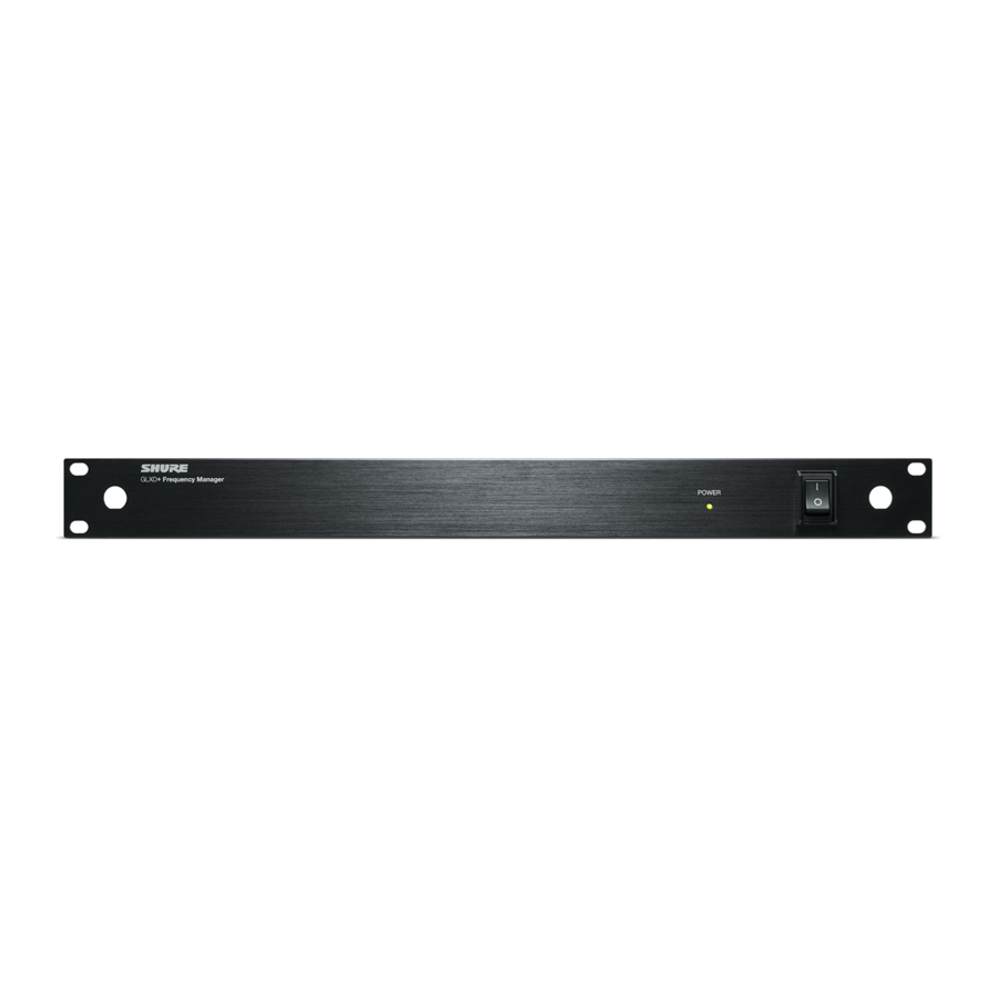
Front and Rear Panels

- Antenna A Connector Mount antenna and connect to antenna A input on rear panel.
- Power LED Illuminates when unit is on.
- Power Switch Powers the system on and off.
- Antenna B Connector Mount antenna and connect to antenna B input on rear panel.
- Power Input Connects to supplied external power supply.
- Power Outputs Connect to receiver power inputs.
- Firmware Update (USB-C) Connect to computer to download firmware updates.
- RF Input Antenna B Use reverse SMA cables to connect antenna.
- Cascade RF B Connector Connect to second frequency manager's antenna inputs, or connect a sixth receiver.
Note: Do not use other RF outputs to connect to a second frequency manager. - RF B Connectors Connect to receiver's antenna B input.
- RF A Connectors Connect to receiver's antenna A input.
- Cascade RF A Connector Connect to second frequency manager's antenna inputs, or connect a sixth receiver.
Note: Do not use other RF outputs to connect to a second frequency manager. - RF Input Antenna A Use reverse SMA cables to connect antenna.
Set Up the Frequency Manager

- Connect each antenna to the antenna A and antenna B outputs on the rear panel.
- If mounting in equipment rack, use included rackmount hardware to mount as shown.
- Connect power supply to power outlet and to the power in on the rear panel.
- Power each receiver by connecting a DC power cable between the frequency manager's power out and the receiver's power input.
- Use reverse SMA cables to connect the frequency manager's RF A and RF B ports to each receiver's antenna A and antenna B inputs.
Note: If mounting antennas remotely, see Remote Antenna Placement.
Selecting Frequency Groups
The frequency manager creates a shared group of frequencies for all receivers to use, and automatically assigns frequencies to each receiver. If interference occurs, the frequency manager assigns new frequencies without audible dropouts.
Using a shared group of frequencies for all receivers prevents one receiver from using all of the best frequencies, and it improves RF reliability.
- Press the power button to turn on the frequency manager.
- Press the power button on the first receiver. The white data sync LED flashes while searching for frequencies.
- Select a group for all receivers by pressing and holding the group button for two seconds.
| Group | Channel Count (Number of Re ceivers)* | Latency | Notes |
| A | Z2: 12 (2.4 GHz only) Z3: 12 (2.4 GHz), 16 (5.8 GHz) Z4: 12 (2.4 GHz), 16 (5.8 GHz) Z5: 12 (2.4 GHz), 15 (5.8 GHz) | 4.6 ms | |
| B | Z2: 15 (2.4 GHz only) Z3: 15 (2.4 GHz), 16 (5.8 GHz) Z4: 15 (2.4 GHz), 16 (5.8 GHz) Z5: 15 (2.4 GHz), 16 (5.8 GHz) | 8 ms | Best group if you experience interference. |
Linking Transmitters and Receivers

Before beginning, turn off all receivers and transmitters. Turn on and link each receiver/transmitter pair one at a time to prevent cross-linking
- After selecting a group using the first receiver, turn on the first transmitter. The blue RF LED will flash while the transmitter and receiver form a link. When the link has successfully formed, the RF LED will remain illuminated.
- Turn on the second transmitter and repeat for each additional receiver/transmitter pair to finish linking.
Connecting Multiple Frequency Managers
Connect 2 frequency managers if using more than 6 receivers, or connect 3 frequency managers if using more than 11 receivers. Use the cascade A and cascade B ports to connect the frequency managers. Frequency managers can be cascaded up to a maximum of 16 receivers.

- Use reverse SMA cables to connect the cascade A and cascade B ports on the first frequency manager to the antenna A and antenna B ports on the second frequency manager. Repeat this sequence to connect the second frequency manager to a third frequency manager.
- Connect receivers according to the diagram. For example, use the A2 and B2 ports to connect a second receiver, then use the A3 and B3 ports to connect a third receiver. When using 2 frequency managers, the cascade A and cascade B ports on the second frequency manager connect to a sixth receiver.
Note: Do not use a passive antenna splitter with the frequency manager. Frequency manager features will not work.
Remote Antenna Placement
Follow these guidelines when mounting antennas remotely:
- Reduce distance between transmitter and antenna.
- Mount antennas farther from each other to improve performance.
- Position antennas so there is nothing obstructing the line of sight to the transmitter, including the audience.
- Keep antennas away from metal objects and any other antennas.
- Use only low-loss reverse SMA cable to avoid poor RF signal.
- Consult cable's specifications and calculate signal loss for desired cable run.
- Use one continuous length of cable from the antenna to the receiver to increase signal reliability.
- Always perform a walk around test to verify coverage before using a wireless system during a speech or performance. Experiment with antenna placement to find the optimum location. If necessary, mark any trouble spots and ask presenters or performers to avoid those areas.
Receiver Channel Display
When connected to a frequency manager, each receiver's channel field displays a unique identifier that won't change unless you plug in to a different set of ports on the frequency manager. Use this channel display to help label transmitters or to identify where each receiver is plugged in on the frequency manager.
| Frequency Manager | Frequency Manager Port Num ber | Receiver Channel Display |
| Frequency manager #1 | 1 | 1 |
| 2 | 2 | |
| 3 | 3 | |
| 4 | 4 | |
| 5 | 5 | |
| 6 (cascade)* | 6* | |
| Frequency manager #2 | 1 | 6 |
| 2 | 7 | |
| 3 | 8 | |
| 4 | 9 | |
| 5 | A | |
| 6 (cascade)* | B* | |
| Frequency manager #3 | 1 | B |
| 2 | C | |
| 3 | D | |
| 4 | E | |
| 5 | F | |
| 6 (cascade) | G |
*There is no receiver channel display when connecting cascade port to second or third frequency manager.
GLXD4+ and GLXD6+ Receivers
GLXD4+ and GLXD6+ receivers cannot connect to the GLX-D+ frequency manager.
If you plan to use a GLXD4+ or GLXD6+ receiver in addition to a frequency manager, set up the GLXD4+/GLXD6+ receiver first. Then turn on and set up the frequency manager.
Note: Using GLXD4+/GLXD6+ receivers alongside a frequency manager will affect the maximum number of channels you can operate with each group.
Optional Accessories and Replacement Parts
| Passive Directional Antenna | PA805DB-RSMA |
| Remote Antenna Mounting Bracket Kit | UA505-RSMA |
| 1/2 Wave Antenna, 45 deg. (2.4 and 5.8 GHz) | UA8-2.4-5.8GHZ |
| 0.6 m (2 ft.) Reverse SMA Cable | UA802-RSMA |
| 1.8 m (6 ft.) Reverse SMA Cable | UA806-RSMA |
| 7.6 m (25 ft.) Reverse SMA Cable | UA825-RSMA |
| 15.2 m (50 ft.) Reverse SMA Cable | UA850-RSMA |
| 30.4 m (100 ft.) Reverse SMA Cable | UA8100-RSMA |
| Power supply | PS60 |
| Reverse SMA Bulkhead Adapters, lockwasher, nut | 95A32436 |
| Nut | 95W8631 |
| Washer | 95X8631 |
Specifications
Power Requirements
15 V DC
DC Output
5 V DC (x6)
Output Current
Combined total from all DC outputs
3.8 A, maximum
Operating Temperature Range
0°C (32°F) to 60°C (140°F)
RF Frequency Range
2400 - 2483.5 MHz and 5725 - 5875 MHz
Gain
| Transmit Mode | 2400 - 2483.5 MHz: 0.5 dB maximum; 5725 - 5875 MHz: 1.0 dB maximum |
| Receive Mode | 1 dB nominal |
Maximum Antenna Input Power
-10 dBm
Maximum Receiver Port Input Power
20 dBm (3 cascades)
Maximum Total Receiver Port Input Power
22 dBm (3 cascades)
Connector Type
Reverse SMA (RP-SMA)
Impedance
50 Ω
Dimensions
19 x 7.47 x 1.73 in. (482.6 x 189.82 x 43.94 mm)
Weight
61 oz (1735 g)
Housing
Steel
IMPORTANT SAFETY INSTRUCTIONS
- READ these instructions.
- KEEP these instructions.
- HEED all warnings.
- FOLLOW all instructions.
- DO NOT use this apparatus near water.
- CLEAN ONLY with dry cloth.
- DO NOT block any ventilation openings. Allow sufficient distances for adequate ventilation and install in accordance with the manufacturer's instructions.
- DO NOT install near any heat sources such as open flames, radiators, heat registers, stoves, or other apparatus (including amplifiers) that produce heat. Do not place any open flame sources on the product.
- DO NOT defeat the safety purpose of the polarized or grounding type plug. A polarized plug has two blades with one wider than the other. A grounding type plug has two blades and a third grounding prong. The wider blade or the third prong are provided for your safety. If the provided plug does not fit into your outlet, consult an electrician for replacement of the obsolete outlet.
- PROTECT the power cord from being walked on or pinched, particularly at plugs, convenience receptacles, and the point where they exit from the apparatus.
- ONLY USE attachments/accessories specified by the manufacturer.
- USE only with a cart, stand, tripod, bracket, or table specified by the manufacturer, or sold with the apparatus. When a cart is used, use caution when moving the cart/apparatus combination to avoid injury from tip-over.
- UNPLUG this apparatus during lightning storms or when unused for long periods of time.
- REFER all servicing to qualified service personnel. Servicing is required when the apparatus has been damaged in any way, such as power supply cord or plug is damaged, liquid has been spilled or objects have fallen into the apparatus, the apparatus has been exposed to rain or moisture, does not operate normally, or has been dropped.
- DO NOT expose the apparatus to dripping and splashing. DO NOT put objects filled with liquids, such as vases, on the apparatus.
- The MAINS plug or an appliance coupler shall remain readily operable.
- The airborne noise of the Apparatus does not exceed 70dB (A).
- Apparatus with CLASS I construction shall be connected to a MAINS socket outlet with a protective earthing connection.
- To reduce the risk of fire or electric shock, do not expose this apparatus to rain or moisture.
- Do not attempt to modify this product. Doing so could result in personal injury and/or product failure.
- Operate this product within its specified operating temperature range.

Documents / ResourcesDownload manual
Here you can download full pdf version of manual, it may contain additional safety instructions, warranty information, FCC rules, etc.
Advertisement
Thank you! Your question has been received!
Need Assistance?
Do you have a question about the GLXD+FM that isn't answered in the manual? Leave your question here.