Table of Contents
Advertisement
Available languages
Available languages
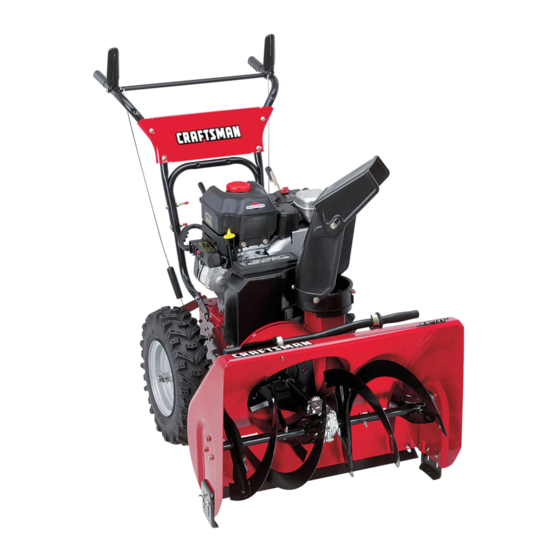
Operator's Manual
Snow Thrower
8,5 Horsepower
Electric Start
27" Dual Stage
Model 536.881851
CAUTION:
Before using this product,
read this manual and follow all of its
Safety Rules and Operating Instructions.
Manual del usario
Quitanieves
8,5 caballos de fuerza (hp)
Arranque el_ctrico
27" Biet_pico
Modelo 536.881851
PRECAUCl6N: Antes de usar este producto,
lea este manual y siga todas las reglas de
seguridad e instruccionesde operacibn.
Sears,
Roebuck
and Co., Hoffman Estates, IL 60179 U.S.A.
198928 Rev. 1 07,19,05 BY
www.sears.com/craftsman
Printed in U,S.A.
Advertisement
Table of Contents

Related Manuals for Craftsman 536.881851


Summary of Contents for Craftsman 536.881851
- Page 1 27" Biet_pico Modelo 536.881851 PRECAUCl6N: Antes de usar este producto, lea este manual y siga todas las reglas de seguridad e instruccionesde operacibn. Sears, Roebuck and Co., Hoffman Estates, IL 60179 U.S.A. www.sears.com/craftsman 198928 Rev. 1 07,19,05 BY Printed in U,S.A.
- Page 2 SERVICE AND ADJUSTMEN1 UMITED TWO-YEAR WARRANTY ON CRAFTSMAN SNOW THROWER For two years from the date of pumhase, when this Craftsman Snow thrower is maintained, lubricated, and tuned up according to the operating and maintenance instructions in the owner's manual, Sears will repair, free of charge, any defect in material or workmanship.
- Page 3 TRAINING Read this operating and service instruction manual carefully. Be thoroughly familiar with the controls and the proper use of the snow thrower. Know how to stop the snow othrower and disengage the controls quick- Never allow children to operate the snow thrower.
- Page 4 14. Donotoverload t hesnow thrower capacity by attempting to clear snow at too fast a rate. Never operate the snow thrower at high transport speeds on slippery surfaces. Look behind and use care when backing Never direct discharge at bystanders or allow anyone in front of the snow thrower.
- Page 5 Drive Clutch Forward Push To Engage Electric Starter Discharge DOWN Discharge Weight Transfer Weight Transfer Lift Handle To Depress Pedal Engage To Disengage SafetyWarningSymbols DANGER Thrown Objects. Keep Bystanders Away. IMPORTANT Read Owner's Manual Before Operating This Machine. WARNING Hot Surface Reverse Auger Clutch Auger Collector...
- Page 6 CONTENTS OF PARTS BAG (ACTUAL SIZE) 1 - Owner's Manual shown) (not 1 - Packet of Fuel Stabilizer (not shown) 1 - Warranty Card (not shown) *Non-Assembly Parts, found in toolbox located on belt cover *2- Shear Pins...
- Page 7 safety glasses or eye shields ARNING: Always wear while assembling snow thrower. TOOLS REQUIRED FOR ASSEMBLY 1 - Knife to cut carton 2 - 1/2 inch wrenches (or adjustable wrenches) 2 - 9/16 inch wrenches (or adjustable wrenches) 2 - 3/4 inch wrenches (or adjustable wrenches) 1 - Pliers (to spread cotter pin) 1 - Screwdriver...
- Page 8 ASSEMBLE THE HANDLE CRANK ASSEMBLY 1. Cut tie holding shift rod to lower handle and move shifter to the first forward gear. Cut and discard the plastic tie that secures the crank assembly. Loosen, but do not remove, the screws, flatwashers, Iockwashers, and hex nuts in the upper holes of the lower handle.
- Page 9 NOTE: If the cables have become dis- connected, connect cables as shown in Figure 7. HOW TO ASSEMBLE THE CHUTE DEFLECTOR 1. Remove the carriage bolt. See Figure 8. 2. Raise the chute deflector into op- erating position. 3. Fasten chute deflector to flange with carriage bolt, Make sure to installwith head of carriage bolt on the inside of the flange.
- Page 10 CHECKLIST Before you operate your new snow thrower, to ensure that you receive the best performance and satisfaction from this quality product, please review the following checklist: P" All assembly instructionshave been completed. v" The discharge chute rotates freely. P" No remaining loose parts in carton. P"...
- Page 11 KNOW YOUR SNOW THROWER READ THIS OWNER'S MANUAL AND SAFETY RULES BEFORE OPERATING YOUR SNOW THROWER. Compare the illustrations with your SNOW THROWER to familiarize yourself with the location of various controls and adjustments. Save this manual for future reference. Auger Drive Lever (right hand)
-
Page 12: Snow Discharge
The operation of any snow thrower can result in foreign objects being thrown into the eyes, which can result in se- vere eye damage. Always wear safety glasses or eye shieldswhile operating the snow thrower. We recommend standard safety glasses or a wide vision safety mask for over your glasses. -
Page 13: Checking Oil Level
For ease of maneuverability in light snow conditions, disconnect the klick pin from the wheel locked position and push into the single wheel drive position (unlocked axle hole only). See Figure 12. K]ick Pin Unlocked Single Wheel Position Drive NOTE: Make sure that the klick pin is in the single wheel drive positionof the axle only and not throughthe locked position. -
Page 14: Starting Engine
Never use engine or carburetorcleaner productsin the fuel tank or permanent damage may occur. Fill the fuel tank only witha fresh, clean, unleaded regular,unleaded premium,or reformulatedautomotivegasolinewitha minimumof 85 octane. DO NOT use mable. Always use caution ARNING: Gasoline when handling or storing gasoline. - Page 15 equipped with a three-wire WARNING: The starter is power cord and plug and is designed to operate on 120 volt AC household current. It must be prop- erly grounded at all times to avoid the possibility of electrical shock which may be injurious to operator. Follow all instructions carefully as sat forth in the "To Start En-...
- Page 16 felt and then pull rapidly to start the engine. Do not allow the recoil starter handle to snap back. Slowly retum the recoil starter handle. If the engine does not start in 5 or 6 tries, See Difficult Starting in the ='l'mubleshooting Table".
- Page 17 TO REMOVE SNOW FROM AUGER to remove snow or debris ARNING: Do not attempt that may become lodged in auger with your hands. Use the cleaning stick to remove snow or debris. A cleaning stick is attached to the top of the auger housing.
- Page 18 CUSTOMER RESPONSIBIUTIES SERVICERECORDS Fillindatesasyou Before complete r egular Each service. Often Change Engine Oil Check and Clean Spark Plug Clean and Inspect SparkArrestor Check Fuel "_ Auger DriveBelt * • Adjust after 2 to 4 hours of use, GENERAL RECOMMENDATIONS The warranty on this snow thrower does not cover items that have been subjected to operator abuse or negligence.
-
Page 19: Specifications
CHAIN LUBRICATION EVERY 25 HOURS Position speed selector lever in first (1) forward gear. 2. Stand the snow blower up on the auger housing end. NOTE: When the crank case if filled with oil, do not leave the snow blower standing up on the... -
Page 20: Lubrication
ENGINE LUBRICATION Check the crankcase oil level before starting the engine and after each eight (8) hours of continuous use. See Figure 18. Add S.A.E. 5W30 motor oil as needed. Synthetic 5W30 is accept- able for all temperatures. Tighten fill cap/dipstick securely each time you check the oil level. - Page 21 nect the spark plug wire and ARNING: Always discon- place it where it cannot make contact with spark plug to pre- vent accidental starting when mak- ing any adjustments or repairs. TO ADJUST SKID HEIGHT This snow thrower is equipped with two height adjustment skids, located on the outside of the auger housing.
- Page 22 HOW TO REMOVE THE SNOW HOOD To access the spark plug, the snow hood must be removed as follows: 1. Remove the choke control knob (see Figure 21). Remove the safety key. Remove the mounting screws (see Figure 22). Slowly remove the snow hood. Make sure that the primer button hose and the Ignition wire are not disconnected.
-
Page 23: Belt Adjustment
To Replace The Belts" in the Service And Adjustment section. Auger Drive Belt If your snow blower will not discharge snow, check the control cable adjust- ment. If it is correct, then check the condition of the auger drive belt. If it is damaged or loose, replace it (see "How... -
Page 24: How To Replace Belts
HOW TO REPLACE THE BELTS The drive belts are of special construc- tion and must be replaced with original equipment replacement belts available from your nearest Sears service center. Some steps requirethe assistance of a second person, How To Remove the Auger Drive Belt if the auger drive belt is damaged, the snow thrower will not discharge snow. - Page 25 Traction Drive E-Ring Swing Plate Axle Rod Remove Bolts Motor Box Auger Housing Traction Drive Belt Belt Guide Auger Drive Pulley Auger Drive Belt Figure 28 TractionDrive Spring Traction Drive Belt Traction Drive Pulley Engine Pulley Figure 29...
- Page 26 How To Remove The Traction Drive Belt If the snow thrower will not move for- ward, check the traction drive belt for wear or damage. If the traction drive belt is worn or damaged, replace the belt as follows, 1. Disconnectthe spark plug wire, 2.
- Page 27 BELT GUIDE ADJUSTMENT Remove spark plug wire. Have someone engage auger drive. Measure the distance between the belt guide and belt. The distance should be 1/8 inch (3.175 mm) for guide. See Figure 31. Belt Guide 1/8 Inch Auger Idler __ (3.175 rnm) Pulley "-'V...
- Page 28 TRACTION DRIVE CABLE ADJUSTMENT 1. Run the engine until the fuel tank is empty and the engine stops. Stand the snow thrower up on the front end of the auger housing. Loosen the bolts on each side of the bottom panel (see Figure 34). Bolt Bottom Panel \_'_...
- Page 29 HOW TO ADJUST OR REPLACE THE FRICTION WHEEL How To Check The Friction Wheel If the snow thrower will not move for- ward, check the traction drive belt, the traction drive cable or the friction wheel. If the friction wheel is worn or damaged, it must be replaced.
- Page 30 How To Replace The Friction Wheel If the friction wheel is worn or damaged, the snow thrower will not move forward. The friction wheel must be replaced as follows. Run the engine untilthe fuel tank is empty and the engine stops. Stand the snow thrower up on the front end of the auger housing (4).
- Page 31 11. Remove the three fasteners that hold the friction wheel to the hub (see Figure 43). 12. Remove the friction wheel from the hub. Slip the friction wheel off the hex shaft. 13. Assemble the new friction wheel onto hub with the fasteners re- moved earlier.
- Page 32 HOW TO REPLACE THE AUGER SHEAR BOLT The augers are secured to the auger shaft with special shear bolts. These shear bolts are designed to break and protectthe machine if an object be- comes lodged in the auger housing. Do not use a harder bolt as the protection provided by the shear bolt will be lost.
- Page 33 If you do not remove the gasoline, usefuel stabilizer suppliedwith unit or purchase Craftsman Fuel Stabi- lizer No. 3550. Add fuel stabilizerto any gasoline left in the tank to mini- mize gum depositsand acids. If the...
-
Page 34: Troubleshooting
TROUBLE CAUSE Defective spark plug. Difficult startlng Water or dirt in fuel system. Engine runs erratically Blocked fuel line, empty gas tank, or stale gasoline Engine stalls Unit running on CHOKE. Engine runs erratic; Water or dirt in fuel system. Loss of power Excessive vibration Loose parts: damaged... - Page 35 (This page applicable in theU.S,a,. a ndCanada only.) Sears, Roebuck and Co., U.S.A. (Sears), the California (CARB) and the United States Environmental Emission Control System Warranty Rights and Obligations) EMISSION CONTROL WARRANTY ENGINES PURCHASED IN CAUFORNIA USED IN CALIFORNIA, AND TO CERTIFIED GINES WHICH ARE PURCHASED...
- Page 36 Warr nted Parts Coverage under this warranty ex- tends only to the pads listed below (the emission control systems parts) to the extent these parts were present on the engine pur- chased. Fuel Metering System • Cold start enrichment sys- •...
- Page 37 Look For Relevant Emissions Durability Period and Air Index Information On Your Engine Emissions Label Engines that are certified to meet the California Air Resources Board (CARB) Tier 2 Emission Standards must display information regarding the Emissions Durability Pe- riod and the Air Index. Sears, Roebuck and Co., U.S.A. makes this information avail- able to the consumer on our emission labels.
- Page 38 CRAFTSMAN 8.5HP SNOW THROWER 536.881851 25-2 25-3 25-2 ENGINE 1,° 25-4 Ref.Drive Page Ref. Auger Housing Page...
- Page 39 CRAFTSMAN 8.5HP SNOW THROWER 536.881851 ENGINE Part No. Description 6219 CORD, ELECTRIC ENGINE, Number 15A114-0342-E1 002x97 BOLT, CARRIAGE 5/16-18 x 1-1/2 028x76 RETAINER, PUSH 71OO26 LOCKNUT, HEX 5/16-18 1501109 PULLEY, ENGINE 710247 WASHER .48 x 1.00 71063 WASHER, SPLIT LOCK 3/8 71015 SCREW 3/8-24 x 1.00...
- Page 40 CRAFTSMAN 8.5HP SNOW THROWER 536.881851 Ref, Engine Page Part No. Description 1501055E701 COVER, BOTTOM 310169 SCREW 1/4-20x5/8 1501226 YZ IDLER, AUGER 711682 PIN, HAIR 761761 PIN, CLEVIS 165x159 SPRING, TENSION 761675 YZ SPRING ATTACH 585781 BOLT, CARRIAGE 711617 WASHER, FLAT...
- Page 41 CRAFTSMAN 8.5HP SNOW THROWER 536.881851 312 _ Part No. Description 10577 CASE, GEAR, RH 10576 CASE, GEAR, LH 710025 SCREW 1/4-20x3/4 15X143 LOCKNUT 1/4-20 9344 SCREW, PLUG 9566 SEAL, OIL 50304 BEARING, FL 48275 WASHER, FLAT 1501307 SHAFT, OUTPUT 51279...
- Page 42 CRAFTSMAN 8.5HP SNOW THROWER 536.881851 Ref. Shift Yoke Page Ref. Page Ref._-- Wheel /220 Page DRIVE Ref. Frame...
- Page 43 CRAFTSMAN 8.5HP SNOW THROWER 536.881851 DRIVE Part No. 1501092 579851 334163 579858 25x020 1501100 579868 337029 1501435 001x38 303008 579859 579858 334163 25x020 1501115 1501057 YZ 1501158 15x114 11x30 1501107 YZ 11x30 165x112 1501090 71074 0011x2 Description LF AXLE, SWING PLATE YZ CHAIN, ROLLER #42x19.00...
- Page 44 CRAFTSMAN 8.5HP SNOW THROWER 536.881851 DISCHARGE CHUTE Ref. Auger Housing Page...
- Page 45 CRAFTSMAN 8.5HP SNOW THROWER 536.881851 DISCHARGE CHUTE Key No, Part No. 2xl 00 71071 71038 71071 1501260 002x97 762222 2X100 71071 71 038 1501932 YZ 02x101 15x145 337227 1501282 DescrlpUon BOLT, 5/16-18 X 1.00 CARG. WASHER, FLAT NUT, 5/16-18 NYLOCK...
- Page 46 CRAFTSMAN 8.5HP SNOW THROWER 536.881851 AUGER HOUSING 542 540 Ref. Gear Case Page 526 525...
- Page 47 CRAFTSMAN 8.5HP SNOW THROWER 536.881851 AUGER HOUSING Key No. Part No. 1501211 577400 2001022 1501158 582957 YZ 1501389 001X92 710026 1502013E549 760661 E701 001)(45 710026 1502017E701 1502016E701 9524 3943 73826 9517 711862 9357 309016E-/01 908156 710026 1501576 1501672 06xl 15...
- Page 48 CRAFTSMAN 8.5HP SNOW THROWER 536.881851 HANDLE \746 p_g_ ,_', 745 760...
- Page 49 CRAFTSMAN 8.5HP SNOW THROWER 536.881851 HANDLE Key No. Part No. 1501205E701 1501206E701 11234 71071 71060 15)(144 11261 337399 337816E701 337815E701 337381 761105 337373 4049 1501123 761872 313441 1673 15)(145 308146 339541 E701 25x021 337407E701 6751 310169 001798 579860 1501059 YZ...
- Page 50 CRAFTSMAN 8.5HP SNOW THROWER 536.881851 CHUTE ROD _870 852-9 852-5 852-8 852-13 Ref, Auger Housing Assy 852-10 852-1 1 ._. 852-1 "- 852-2 852-6 852-7 852-3...
- Page 51 CRAFTSMAN 8.SHP SNOW THROWER 536.881851 CHUTE ROD Key No. Part No. 852-1 1501309 YZ 852-2 313431 852-3 1501067 852-5 579493 852-6 1501306E701 852-7 1501293 852-8 1501075 YZ 852-9 711682 852-10 578060 852-11 578309 852-13 578063 51443 309312 73664 1501456 71045...
- Page 52 CRAFTSMAN 8.5HP SNOW THROWER 536.881851 _-. 796 Part No, Key No. 336702E701 302628 73826 331624 760564 302628 73826 1501085 YZ 11x30 579944 SHIFT YOKE Description ROD, SHIFT SCREW, 1/4-20X.75 NUT, 1/4-20 KNOB, SLIP LEVER, SPRING SCREW, 1/4-20X.75 NUT, 1/4-20 ROD ASSY., SPEED SELECT...
- Page 53 CRAFTSMAN 8.5HP SNOW THROWER 536.881851 Ref. Drive Page Key No. Part No. 1501563 1501089 01x193 15X145 1501114 712120 1501138 1501808 577015 15X145 73842 1501809 WHEELS Description SHAFT, AXLE SPRK-I" & HUB SCREW, 1/4-20 x 1.75 NUT, 1/4-20 HEX NYLOCK Y'Z...
- Page 54 CRAFTSMAN 8.5HP SNOW THROWER 536.881851 PANEL Part No. 1501203E201 002x99 71067 15x145 DECALS Pa_ No. Description 48x5580 DECAL 48x5286 DECAL DANGER & FOOT * 46x5578 DECAL DANGER THROWN OBJECTS 48x5590 DECAL TRACTON/AUGER 48x5626 DECAL SPEED SELECT 760983 DECAL TOOL BOX - BELT COVER...
- Page 55 NOTES...
- Page 56 BRIGGS & STRA'n'ON ENGINE MODEL 15A114-0342-E1 I 1019 LABEL KIT I _2 0 Assemblies Include all parts shown In frames.
- Page 57 BRIGGS & STRA'I-FON ENGINE Part No. Description 791762 Cylinder Assembly 399269 Kit-Bushing/Seal (Magneto Side) *299819 Seal-Oil (Magneto Side) 791720 Head-Cylinder 7*0791716 Gasket-Cylinder Head 695745 Tube-Breather 699485 Gasket-Crankcase 699482 Screw (Cylinder Head) 691686 Plug-Oil Drain 695757 Plug-Oil Drain 791721 Crankshaft 222698 Key-Flywheel 791786 Piston Assembly...
- Page 58 BRIGGS & STRATTON ENGIN E 692 I ,_, _P_. 130_ "_ 95 _ 127 _ 127A o 276 _" 977 CARBURETOR GASKET SET 51 _ 633A _ Assemblies MODEL 15A114-0342-E1 287 _, 524 _ _,,:_ 663 3_ 281 _, _ _...'-'_"...
- Page 59 BRIGGS & STRA'I-I'ON ENGINE Part No. Description ,_B99485 Gasket-Crankcase 699800 Cover-Crankcase *692550 Seal-Oil (PTO Side) 281658 Cap-Oil Fill 599478 Screw (Metric) (Crankcase Cover/Sump) 51,4,._692555 Gasket-Intake (2 Required) 691636 Screw (Throttle Valve) 690024 Shaft-Throttle 398185 Kit-Idle Speed o691242 Pin-Float Hinge 695807 Valve-Choke 695729 Shaft-Choke...
- Page 60 BRIGGS & STRATrON ENGINE 1036 EMISSIONS LABEL 11871 _ [601 vyl 190_' 1251A 49381 _ 1251 1252_ Assemblies MODEL 15A114-0342-E1 lOOSi 1070 _' 1210 1211 472 _, 1196A 1095 VALVE GASKET SET (Oo ', I_,\ \_J&o\ Include all parts shown In frames. ¢...
- Page 61 BRIGGS & STRATTON ENGINE Part No. Description ,299819 Seal-Oil (Magneto Side) 7 *_791716 Gasket-Cylinder Head *699485 Gasket-Crankcase -*692550 Seal-Oil (PTO Side) 699516 Flywheel 51..._692555 Gasket-intake 696710 Housing-Rewind Starter 693389 Rope-Starter (Cut to Required Length) 699334 Grip-Starter 699851 Screw (Rewind Starter) 693401 Line-Fuel (Molded)
- Page 62 Si este quitanieves Craftsman es usado con prop6sitos comerciales o de arrendamiento, esta ga- rantia serd v_.lidasolamente por 90 dias a partir de la fecha de compra.
- Page 63 ves tlenela eapa©idad de ampu- ADVERTENCIA: E ste quitanle- tar las extremldades y de lanzar obJetos con velocldad. No respetar laa si- gulentes instrucclones de seguridad pue- de resultar en leslones graves. CAPACITACI6N Lea con atenci6n las instrucciones an el manual de operaci6n y servicio.
- Page 64 CAPACITACION Lea con atenci6n las instrucciones en el manual de operaci6n y servicio. Familiari- cese completamente con los controles y el uso apropiado del quitanieves. Apren- da a detener el quitanieves y a desen- ganchar rdpidamente los controles. Nunca permita a ni_os operar el quita- nieves.
- Page 65 necteel cabledela bujiay mantdngalo alejado de la bujfa para evitar un arran- que accidental. Tome todas las precauciones posibles al dejar el quitanieves desatandido. Desen- ganche la barrena/propulsor, pare el mo- tor y retire la Ilave. 10. No haga arrancar el motor en recintos cerrados, at_n con las puertas y ventanas abiertas.
- Page 66 IMPORTANTE: Muchos d eestos simbolos est_ colocados o nsuquitanieves o estdnimpreso6 los manuales que vienen con el producto. Antes de operar el quitanieves aprenda y comprenda el objetivo de cada simbolo, SIMBOLOS DE CONTROL Y OPERACI6N Despacio R4pido Motor en marcha Motor apagado aAhcl i°i°i°i°_vaad_...
- Page 67 SiMBOLOS DE CONTROL Y OPERACI(_N Combustible Acelte Descarga hacla Descarga hacla ABAJO ARRIBA Transferencla de peso Transferencla Levante el mango para enganchar. Simbolos de advertencla de seguridad PELIGRO ObJetos lanzados. Mantenga alelados a los transeuntes, IMPORTANTE Evlte las leslones que puede Lea el manual del propietario antes de...
- Page 68 CONTENIDO DE LA BOLSA DE PARTES ('I'AMA_IO REAL) 1 - Manual del Propietario (no se muestra) 1 - Paquete de estabilizador de combustible (no se muestra) 1 - Tarjeta de garantia (no se muestra) *Las partes que no necesitan ensamblado se encuer_an en la caja de herramientas ubicada en la cubierta de la correa.
- Page 69 gafas de seguridad o protecto- DVERTENCIA: Siempre use res para los oJos mlentras en- sambla el quitanleves. HERRAMIENTAS NECESARIAS 1 - Navaja para codar cart6n 2 - Llave de tuercas de 1/2 pig (o Ilave de tuercas ajustable) 2 - Llave de tuercas de 9/16 pig (o Ilave de tuercas ajustable) 2 - Llave de tuercas de 3/4 pig (o Ilave de tuercas ajustable)
- Page 70 C(_MO ENSAMBLAR EL MANGO Y EL CONJUNTO DE LA MANIVELA Corte los amarres que sujetan la palanca de cambios al mango inferiory mueva la palanca a la primera velocidad de avarice. Corte y deseche el amarre de plds- tico que sujeta el conjuntode la ma- nivela.
- Page 71 NOTA: Si los cables se han desconec- tado, con_-'telos como se muestra en la Figura 52. C(_MO ENSAMBLAR EL DEFLECTOR DEL TUBO DE DESCARGA Quite el perno cabeza de hongo. Vea la Figura 53. Levante el deflector del tubo de descarga a la posici6n de opera- ci6n, Monte el deflector...
- Page 72 USTA DE REVISI6N Antes de usar su nuevo quitanieves, y para asegurar que obtenga el mejor rendimiento y la mayor satisfacci6n de este producto de calidad, por favor haga un repaso de la si- guiente lista de revisi6n: Se hart completado todas las instruccio- nes de ensamblado.
- Page 73 CONOZCA SU QUITANIEVES LEA ESTE MANUAL DEL USUARIO Y I_AS REGLAS DE SEGURIDAD ANTES DE USAR USAR SU QUlTANIEVES. Compare las figuras con su QUITANIEVES los posiciones de los diversos controles y ajustos. Guarde este manual para referencia futura. Palanca de pmpulsibn de la barrena Estran ulador...
- Page 74 Laoperaci6n de cualquier q uitanieves p uede ocasionar q ueobjetos extrafiosseanlanza- dosconfuerzahacialosojos,Iocualpodria resultar e nlesiones graves. U sesiempra gafasdeseguridad o protectores p aralos ojosmientras operael quitanieves. Serecomiendan l asgalasdeseguridad es- t_mdar o la m_scara de seguridad de visidn amplia para usada sobre los anteojos. del propietarlo antes de operar ADVERTENClA:...
- Page 75 agujero para tracci6n de una rueda (des- enganche solamente el aguJerodel eJe). Figura 57, Pasador klick Posici6n de Tracci6n en una sola rueda Figura 57 NOTA: Aseg_rese de que el pasador klick est_ en la posicibn de traccidn de una sola rueda en el eje solamente, y no est_ inserta- do a trav_s de la posici6n de enganche.
- Page 76 Iocontrario podriacausarda_opermanente ala unidad. Lleneel tanquesolamente congasolina free- ca,limpia,regular s in plomo,s_persinplo- moo gasolina automotor reformulada con un octanaje minimo de 85. NO use gasolina inflamable y debe tener mucho DVERTENCIA: La gaeolina es cuidado el manipulerle elameenarla. Apague el motor y deje que se enfrie por Io menoe por doe minutoa antes de quitar la tape del tenque de com- bustible.
- Page 77 arranque est=t equipado con un DVERTENCIA: El motor de cable de aUmantacl6n y enchu- fe trlfllar, disefiados para funcionar con corriente dom6atlca de 120 voltios CA. El cable de allmentacl6n deberd estar co- nactado a Uerra en todo momento para evitar la posibilldad de un choque el6ctri- co que podr|a lesionar al operador.
- Page 78 tre arranques para permRJr q ue el motor de arranque se enfHe. 8. (Arranque a manual) Jale lentamente la manija de arranque manual has- ta que sienta resistencia y entonces j_.lela r_.pidamente para arrancar el motor. No suelte la manija inmediata- mente despu_s de jalarla.
- Page 79 COMOQUITAR LANIEVEY ESCOMBROS ATASCADOS D E LABARRENA tar la nieve ni escombros ADVERTENCIA: No Intente qul- cados en la barrena con sus manos. Use el la barra de Iimpleza para quitar la nieve o escombros. En la parte de arriba del alojamiento de la ba- rrena se encuenka un bast6n de limpieza.
- Page 80 RESPONSABlUDADES DELPROPIETARIO REGISTROS SERVIClO Anote lasfechas e n Antes que eehace manteni- deca- Ame- miento r e9ular dauso nudo horas horas horas horn Cambiarel aceitedel motor Revisarla bujla Umpiar y examinarel parachispas Revisarel combustible _/" Correade propulsibn de la barrena* * Ajustar despu_s de 2 a 4 horas de uso.
- Page 81 MOTOR ESPEClFICAClONES CABALLOS 8.5 HP FUERZA CILINDRADA 249 cc CALIBRE 75mm (2,970 pulg.) CARRERA 56mm (2,205 pulg.) CAPACIDAD 3 cuartos GASOLINA (sin plomo) CAPACIDAD DE 18 onzas, 5W30 ACEITE Champion RJ19LM BUJiA: (Entrehierro 0,030pig.) JUEGODE Entrada: 0,004-0,006 VALVULA: Escape: 0,009-0,011 pig. :NTREHIER- :10 DEL 0,010-0,014...
- Page 82 MOTOR LUBRICACI(_N Revise el nivel de aceite en el c_Lrterdel mo- tor antes de encenderlo y despuds de cada ocho (8) horas de uso continuo. Figura 63. Agregue aceite de motor S.A.E. 5W30 a me- dida que sea necesario. El aceite sintdtico 5W30 es aceptable para cualquier temperatura.
- Page 83 el arranque accidental del mo- ADVERTENCIA: Para prevenir tor, alempre desconecte ble de la buJia y mant6ngalo aleJado de 6sta mlantras reallza aJustes o repara- clones a la unldad. C_MO AJUSTAR LOS PATINES ALTURA Este quitanieves est_ equipado con dos pati- nes de ajuste de altura, ubicados en el lado exterior del alojamiento de la barrena.
- Page 84 COMO DESMONTAR LA CUBIERTA PROTECTORA Para acceder a la bujia es necesario quitar la cubierta protectora: 1. Quite el estrangulador (vea la Figura 66). 2. Saque la Ilave de seguridad. 3. Quite los tornillos de montaje (Figura 67). 4. Retire cuidadosamente la cubierta protectora.AsegOrese de que la manguera del bot6n cebador y el cable de ignicibnpermanezcan con-...
- Page 85 AJUSTE DE LAS CORREAS Correa de propulsi6n La correa de propulsi6ntiene una presibn de resorteconstantey no re- quiere ning_najuste. Si nota que em- peza a resbalar, reempldcela. Consulte =C6mo reemplazar la correa" en la sec- ci6n de Servicio y Ajustes. Correa de propulsi6n de la barrena Si el quitanieves...
- Page 86 2. Afloje los pernos a cada lado del panel inferior (Figura 72). 3. Quite el panel inferior. Pemo Quite el tornillo de la cubierta de la correa. Quite la cubierta (Figura 70). 5. Afloje la guia de la correa. Separe la guia de la polea de propulsibn de la barrena (Figura 74).
- Page 87 Polea Polea guia ae Anillo E ._ Eje de la placa oscilante Retire pemos pernos Hi Caja del motor Alojamiento de la barrena Gufa de la correa Polea de propulsibn de la barrena Correa de pmpulsi6n de la barrena Resorte de propulsi6n Correa de propulsi6n...
- Page 88 C6mo desmontar la correa de propulsi6n Si el quitanieves no se mueve hacia adelante, asegt_rese de que la correa de pmpulsi6n no est6 excesivamente desgastada o da_ada. Si Io est,., reempl_tcelade la siguiente manera. 1. Desconecte el cable de la bujfa. Quite la correa de propulsi6n de la barrena.
- Page 89 AJUSTES DE LA CORREA 1. Quite el cable de la bujfa. Pida a alguien que ponga el propul- sot de ta barrena. Mida la distancia entre la gu{a de la correa y la correa. La distancia de- be ser de 1/8 de pulgada (3,175 mm) para la gufa.
- Page 90 AJUSTES DEL CABLE DE PROPULSIC)N 1. Deje el motor en mamha hasta que el tanque de combustible quede va- cfo y el motor se pare. Levante el quitanieves con el extre- mo frontal del alojamiento de la ba- rrena hacia abajo. 3.
- Page 91 C(_MO AJUSTAR O REEMPLAZAR LA RUEDA DE FRICCI(_N Cbmo revisar la rueda de friccibn Si el quitanieves no avanza, revise la correa de propulsi6npot tracci6n, el ca- ble de propulsi6no la rueda de fricci6n. Si la rueda de friccibn estd gastada o da_ada, hay que cambiarla.
- Page 92 C6mo reemplazar la rueda de fricci6n Si la rueda de friccibn est& gastada o daSada, el quitanieves no avanza. La rueda de fricci6n se debe cambiar de la siguiente manera. 1. Deje el motor en marcha hasta que el tanque de combustible quede va- cloy el motorse pare.
- Page 93 12. Quite la rueda de fricci6n del cu- bo. Deslice la rueda de fricci6n fuera del eje hexagonal, 13. Instale la nueva rueda de fricci6n en el cub0 con los sujetadoresque quit6 antes. 14. Instale el eje hexagonal y los coji- netes con los cuatro pernos que quit6 antes (Figura 89).
- Page 94 C()MO REEMPLAZAR LOS PERNOS DE SEGURIDAD DE LA BARRENA Las barrenas est_ln sujetas al eje de la ba- rrena con pemos de seguridad especialas. Estos pemos astern disefiados para romper- se y proteger la m&quina en caso de que un objeto se atasque en el alojamiento de la barrena.
- Page 95 de su quitanieves con gaso- ADVERTENCIA: Nunca guar- lina en el tangue de combus- tible en amblentes interiores o en un drea cerrada y real vsnUlada. Si queda gasolins en el tanque, los va- pores podr|an alcanzar alguna lla- ma expuesta, chispa o llama piloto de una caldera, calentador agua, secadora de ropa, cigarrillo,...
- Page 96 PROBLEMA CAUSA Diflcultad de Bujia defectuosa. i arranque Agua o suciedad en el sistema de combustible. El motor funciona Linea de combustible bloqueada, err_ticamente falta de combustible o mezcla de combustible vieja, El motor se pare Unidad funcionando con estrangulador activado, El motor funciona Ague o suciadad an el sistema err6Ucamente;...
- Page 97 (Esta pdgina e saplicable _nicamente enEstados Unidos deArnica y Canad=t.) Sears, Roebuck and Co., U.S.A. (Sears), Junta de Recursos Amblentales (CARB) y Agencla de Proteccl6n Amblental Declaraclbn de la Gerant|a del Sistama de Control de Emisiones (Derechos y Obllgaclones del Propletario LA COBERTURA DE I.A GARANTIA DEL CON- TROL DE EMISIONES ES APLICABLE A LOS MOTORES...
- Page 98 Provlslonasde la Garant|ade Defectosdel Slstemade Controlde EmisionesSears Lassiguientas s onpmvisionas a specificas lativas a la Cobertura de Garantfa de Defectos del Sistema de Control de Emisionas. Es una adici6n de la garantfa del motor Sears para los motores no-regulados encontrados Instrucciones de Mantenimiento y Operaci6n.
- Page 99 Busqueel Periodo de Durabilidadde Emisionesy la Informaci6ndel indice de Aire Pertinentesen su Etiqueta de Emisionesdel Motor Los motores que son certificados para cumplir con las Normas de Emisiones Etapa 2 de la Junta de Recursos Ambientales de California (CARB) deben mostrar la informaci6n referente al Perio- do de Durabilidad de Emisiones y al Indice de Aire.
- Page 100 For repair - in your home - of all major brand appliances, lawn and garden equipment, no matter who made it, no matter who sold iU For the replacement owner's manuals that you need to do-it-yourself. For Sears professional _iiiiii!_ii and items like garage door openers and water heaters.