Table of Contents
Advertisement
Quick Links
Advertisement
Table of Contents

Summary of Contents for NBK EORP-200
- Page 1 Instruction Manual Repeater Hubs...
-
Page 2: Introduction
Introduction We wish to thank you for purchasing Repeater Hubs (EORP-200) from NBK. Carefully read this manual to ensure proper operation. "1. Safety Precautions" is an especially important section. Be sure to fully understand the contents of that section before use. - Page 3 Check the Packaged Items Main unit (x1) Hex socket head cap screws Simple Guide Model: EORP-200 M3×8 (x4) Instruction Manuals for Wired/Wireless Positioning Units Prepare the following manuals according to the products you have purchased. All of the following PDF instruction manuals can be downloaded from our product page: https://www.nbk1560.com/en-US/products/mechatronics/positioning_unit...
-
Page 4: Table Of Contents
Contents Introduction 1 Safety Precautions Essential Precautions Precautions Related to Installation and Wiring Work Precautions Related to Operation and Inspection 2 Overview Product Overview Part Names and Functions Cables for Repeater Hubs (Optional) 2.3.1 Reading Product Numbers 2.3.2 Cable Connector Pinouts and Signal Assignment Block Diagram 3 Specifications 4 Installation and Connections... -
Page 5: Safety Precautions
Safety Precautions Essential Precautions To ensure safety, please thoroughly read the following precautions and understand correctly before using this product. (1) When setting up a system that includes wired/wireless positioning units, be sure to confirm the specifications of each equipment and device used in the system, and make sure that they are operated within their specified ratings and performance limits. -
Page 6: Precautions Related To Installation And Wiring Work
Safety Precautions 1.2 Precautions Related to Installation and Wiring Work WARNING [Perform as Indicated in Order to Prevent Injury, Electric Shock, Fire, and Failure] ・ Be sure to install the product in a safe and secure manner to prevent fire or accidents in case of an earthquake. - Page 7 Safety Precautions CAUTION [Perform as Indicated in Order to Prevent Injury, Electric Shock, Fire, and Failure] ・ Ensure that the wiring work is correctly performed and install according to the specified procedure. ・ Be sure to use a DC power supply (+24 V) that provides stable operation to power a 24 VDC SELV circuit.
-
Page 8: Precautions Related To Operation And Inspection
Safety Precautions 1.3 Precautions Related to Operation and Inspection WARNING [Perform as Indicated in Order to Prevent Injury, Electric Shock, Fire, and Failure] ・ Be sure to perform maintenance and inspection on a monthly basis and ensure that adequate space is provided for such work. COMPULSORY / INSTRUCTION [Prohibited Actions in Order to Prevent Injury, Electric Shock, Fire, and Failure]... -
Page 9: Overview
Overview 2.1 Product Overview Repeat Hubs (EORP-200) ・ Wired/Wireless positioning units can be easily connected using cables. ・ Up to eight wired/wireless positioning units can be connected to a single repeater hub unit. A repeater hub is a device that passes the communication signals received from the host (PC/ PLC) or a transceiver to other ports (wired/wireless positioning units). -
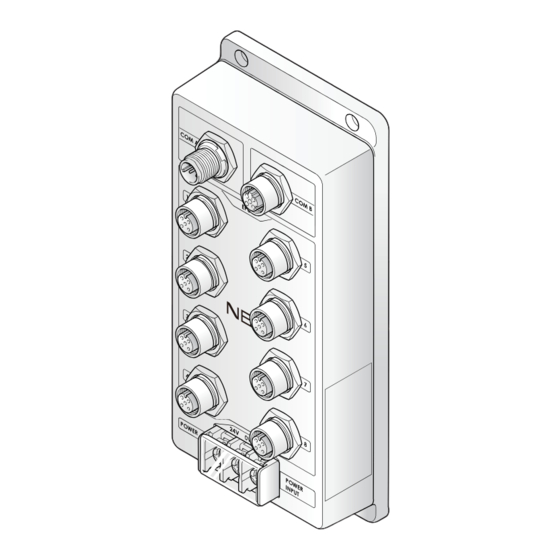
Page 10: Part Names And Functions
Overview 2.2 Part Names and Functions COM A connector Main unit mounting hole Used to connect the host or the transceiver, or a repeater hub that is close to the host. Used to install the main unit. Name Description EPU-210 EPU-220 ー... -
Page 11: Cables For Repeater Hubs (Optional)
Overview 2.3 Cables for Repeater Hubs (Optional) 2.3.1 Reading Product Numbers EOCA-200-A-2 Cable length 2: 2 m (6.6 ft) Series name 5: 5 m (16 ft) EOCA-200: Cables for Repeater Hubs Connected devices A: Host/transceiver - repeater hub B: Repeater hub - repeater hub C: Repeater hub - wired/wireless positioning unit 2.3.2 Cable Connector Pinouts and Signal Assignment ●... -
Page 12: Block Diagram
EOCA-200-C M12 A-code M12 A-code 4-pin shielded male 4-pin shielded female Signal Assignment Pin No. EPU-210 Signal Name EPU-220 2.4 Block Diagram Repeater Hubs (EORP-200) Isolation M12/ M12/ RS-485 RS-485 (COM A (COM B D-code/4-p㏌/ D-code/4-p㏌/ driver driver connector) connector) -
Page 13: Specifications
Specifications Operating Environment Temperature -5 to 55℃ (23 to 131℉) (no freezing) Operating environment Humidity 20 to 85% RH (no condensation) Repeater Hubs (EORP-200) Power supply voltage 2 4 VDC ± 10% Rated Current Standby 60 mA consumption Max. COM A... - Page 14 Specifications ●EOCA-200-B Product No. EOCA-200-B-2 EOCA-200-B-5 Cable Shielded movable cable Sheath material Sheath outer diameter 6.4 mm ± 0.2 mm (0.252 in. ± 0.008 in.) Number of core wires Conductor cross-sectional area AWG26 M12 D-code 4-pin shielded male Cable terminal M12 D-code 4-pin shielded female Fixed installation 26 mm (1.024 in.)
-
Page 15: Installation And Connections
Installation and Connections 4.1 Installation Requirements The environmental conditions for installation are shown below. Be sure to install the product in an appropriate environment. ・ An indoor environment. ・ A place where it is not exposed to direct sunlight (UV rays). ・ A place free of continuous vibration. ・ An installation surface that has sufficient strength. -
Page 16: Repeater Hub Installation
Installation and Connections 4.2 Repeater Hub Installation 4.2.1 Main Unit Installation According to the diagram below, drill 60 (2.362) four screw holes into the surface on 4-M3x0.5 which you wish to mount the repeater Effective screw hub. depth 4 (0.157) or more Unit: mm (in.) Mount the product using the ①... -
Page 17: Connector Installation
Installation and Connections 4.2.2 Connector Installation Confirm the position of the ① Notches ① Notches and insert the connector straight into the repeater hub. Secure the connection by tightening the ② Knurled knob at the end of the connector on the cable. ②... -
Page 18: Power Supply Wiring
Installation and Connections 4.2.3 Power Supply Wiring Remove the ① Protective cover from the power supply terminal block. ① Protective cover Insert the ② Power supply terminal into the power supply terminal block ③ Phillips head and secure it in place with the ③ screw Phillips head screw. -
Page 19: Extending Cables For Repeater Hubs
Installation and Connections 4.2.4 Extending Cables for Repeater Hubs Extending Cables for Repeater Hubs To extend a repeater hub, connect the cables by following the instructions below. ●Extension of EOCA-200-A Use EOCA-200-B when extending EOCA-200-A. Connect EOCA-200-B EOCA-200-A ●Extension of EOCA-200-B Use EOCA-200-B when extending EOCA-200-B. - Page 20 Installation and Connections Connections between Cables for Repeater Hubs Confirm the position of the ① Notches ① Notches and insert the cable connectors in a straight direction. Secure the connection by tightening the ② Knurled knob at the end of the connector.
-
Page 21: Connections
If Using a PC as the Higher-level Host to Control the Unit Terminating resistor (120 Ω) Cables for repeater hubs Cables for repeater hubs (Optional) (Optional) EOCA-200-B EOCA-200-A Repeater hubs Repeater hubs EORP-200 EORP-200 COM A COM B COM A D- D- D- connector connector... - Page 22 Connection Example 2 If Using a PLC as the Higher-level Host to Control the Unit Cables for repeater hubs Cables for repeater hubs (Optional) (Optional) EOCA-200-A EOCA-200-B Terminating resistor (120 Ω) Repeater hubs Repeater hubs EORP-200 EORP-200 COM A COM B COM A D- D- D- connector connector connector D-...
-
Page 23: Maintenance
Maintenance To ensure safe operation, be sure to perform inspections on a monthly basis. If any abnormality is found, immediately stop operation and do not restart until the issue has been resolved. 5.1 Precautions for Inspection ・ The operator shall be responsible for turning the power on and off. ・ Be sure to carry out the following inspections periodically to prevent accidents. -
Page 24: Troubleshooting
Troubleshooting Explanation Symptom Verification Countermeasure Page Is the power supply Make sure the voltage level is Power lamp P.12 voltage correct? within 24 V ±10% does not light Is the power supply cable Wire correctly P.17 connected correctly? P.16 Is the connector properly connected correctly? P.18 Units wired... -
Page 25: Dimensional Outline Drawings
Dimensional Outline Drawings EORP-200 (Unit: mm (in.)) 86 (3.386) 7 (0.276) 60 (2.362) (0.512) 35 (1.378) (51.2 (2.016)) -
Page 26: Emc Precautions
(3) Important safety parts of machinery and equipment (e.g. safety devices) (4) Handling equipment for objects that cannot be replaced, such as cultural properties and works of art Connection example Repeater hubs Repeater hubs EORP-200 EORP-200 Transceiver EPC-200-CC EOCA-200-A EOCA-200-B... -
Page 27: Laws And Regulations
From the following terms. EMC Directive: 2014/53/EU RoHS Directive: (EU)2015/863 Product Name: Repeater Hubs Model Name: EORP-200 Manufacturer: Name: Nabeya Bi-tech Kaisha Add: 1, Toko-Taichi, Seki City, Gifu 501-3939, Japan The full text of the EU declaration of conformity is available at the following internet address: https://www.nbk1560.com/products/mechatronics/positioning_unit/download/eorp-200-doc/... -
Page 28: Usa (Fcc)
Laws and regulations 9.2 USA (FCC) This device complies with part 15 of the FCC Rules. Operation is subject to the following two conditions: (1) This device may not cause harmful interference, and (2) this device must accept any interference received, including interference that may cause undesired operation. -
Page 29: Korea (Kcc)
Laws and regulations 9.4 Korea (KCC) 인증번호: R-R-NbK-EORP-200 사용자 안내문 이 기기는 업무용 환경에서 사용할 목적으로 적합성평가를 받은 기기로서 가정용 환경에서 사용하는 경우 전파간섭의 우려가 있습니다. -
Page 30: Warranty
Warranty Warranty Period: One year after delivery. Warranty Scope: Under normal usage conditions in accordance with this manual, repairs or replacement shall be provided free of charge as long as the failure occurred within the warranty period. However, a fee may be charged in any of the following cases even if occurring within the warranty period: ・ When the issue related to the claim was caused by improper use, repairs, or modifications. -
Page 31: Revision History
Revision History Date ID No. Revision Details Feb. 2022 UM-EORP200-SU-01E First edition... - Page 32 First edition Feb. 2022 UM-EORP200-SU-01E...