
Related Manuals for NAVTELECOM SMART S-2433


Summary of Contents for NAVTELECOM SMART S-2433
- Page 1 GPS/GLONASS TRACKING EQUIPMENT SMART S-2433 Operations manual Installation and connection of the device v1.0 MOSCOW 2020...
- Page 2 Customers are strongly advised to study this document carefully before the installation and operation of the device. Navtelecom LLC is interested in constantly improvement of the manufactured products quality. Please, contact our technical support by email address: support@navtelecom.ru...
-
Page 3: Table Of Contents
ONTENTS ............................2 ONTENTS 1. BASIC CHARACTERISTICS ......................3 1.1 Purpose of the system ......................3 1.2 System tasks ..........................3 1.3 Operational principles ......................3 1.4 Basic technical characteristics ....................4 1.5 Appearance of the device ......................6 1.6 Standard equipment set ......................7 1.7. -
Page 4: Basic Characteristics
1. BASIC CHARACTERISTICS 1.1 Purpose of the system The equipment is a GPS-GSM Based Vehicle Tracking System. It is allowed to use the following terms in relation to this device: “system”, “product”, “equipment”, “device” “terminal”, “tracker”. The system is designed for: ... -
Page 5: Basic Technical Characteristics
1.4 Basic technical characteristics Tab 1 S-2433 GSM/GPRS/Bluetooth GSM 850, EGSM 900, DCS 1800, PCS GSM frequency bands 1900 GPRS class B, multislot class 12 Class 4 (2W) в GSM 850 и EGSM 900; Transmitter power Class 1 (1W) в DCS 1800 и PCS 1900 Maximum speed of data transfer/reception, kbit/s 85,6 SIM card holder 1... - Page 6 Working range with frequency fuel level sensors, Hz 1 - 3000 USB interface for settings, control, data transfer and diagnostics RS-485 digital interface RS-232 digital interface CAN digital interface 1-Wire interface Number of outputs of the “open collector” type for the external devices control Maximum switching current by the control outputs, mA Maximum switching voltage by the control outputs, V...
-
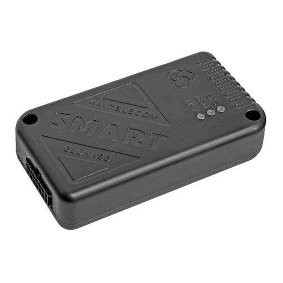
Page 7: Appearance Of The Device
1.5 Appearance of the device On the front part of the device unit (Figure 1) is located: 14-pin connector of Microfit-14 type for connection of power supply, digital and analog sensors and control lines. On the side of the device unit (Figure 2) is located: ... -
Page 8: Standard Equipment Set
1.6 Standard equipment set Tab. 2 Version of complete set № Name Number of pieces Device unit 14-pin connector of Microfit-14 with two power wires Cable set of 5 installation wires Interface cable with MiniUSB connector Passport Package Figure 4. 14-pin connector of Microfit-14 Figure 5. - Page 9 Figure 7. Fuel level sensor Figure 8. Tachograph Figure 9. External LED Figure 10. Temperature sensor Figure 11. TouchMemory contact key reader The manufacturer reserves the right to complete the devices with equipment whose set, appearance and characteristics differ from those shown in the figures.
-
Page 10: Device Components
1.7. Device components The device consists of the following elements (see Figure 12-15): 1) front cover; 2) fixing hole; 3) system LED indicator; 4) GSM LED indicator; 5) GLONASS / GPS LED indicator; 6) 14 pin connector; 7) MiniUSB connector; 8) SIM-card 1 ejector holder;... - Page 11 Figure 14 Figure 15...
-
Page 12: Device Interface Connector
1.8 Device interface connector Figure 16. System 14-pin interface connector 1 - Power “Plus” (+ U 2 – “Ground” (GND) 3 - Universal input 1 (UIN1) 4 - Universal input 2 (UIN2) 5 - Universal input 3 (UIN3) 6 – Output 1 "open collector" (OUT1) 7 –... -
Page 13: Device Connecton
2. DEVICE CONNECTON 2.1 Installation Before the system installation, first of all, it is necessary to determine the type and number of the connecting sensors, the identification system and other additional equipment. It is also necessary to be sure that all the additional equipment connected to the terminal are operable. -
Page 14: Sim-Card Installation And Operation
2.2 SIM-card installation and operation The device supports using of one SIM-card. The SIM card (external) installation is carried out without the use of special tools. Figure 18. SIM-card installation to the device Remove the SIM card holder from the device by pressing the yellow ejector button with a pen or a pencil. Place the SIM card in the holder with the gold contacts facing out. -
Page 15: Universal Inputs Connection
Fuse (1А) «-» «+» «GND» Car battery Figure 19. Power connection 2.4 Universal inputs connection 2.4.1 Analog sensors connection The device allows to measure the voltage applied to the inputs in the range of 0 ... 31 V. When connecting analog FLS or other sensors for which the output voltage has to be monitored, the voltage measurement profile must be set in the inputs setting. - Page 16 CPU_pull-up CPU_adc Figure 21. Connection of normally open (NO-) sensors CPU_pull-up CPU_adc Figure 22. Connection of normally closed (NC-) sensors Profiles "Discrete NC+" and "Discrete NO+" allow to work with sensors, which, when turned on or off, close the input to “+”...
-
Page 17: Pulse Frequency Sensors Connection
CPU_pull-up CPU_adc Figure 24. Connection of normally closed (NC+) sensors Note: It is recommended to connect one of the universal input (usually UIN1) to the vehicle ignition line and make the appropriate setting in the configuration. However, such connection is not mandatory. In addition to the source of notifications about turning on and turning off events, the input is used in coordinate processing algorithms (for example, when they are averaged at parking lots), energy saving, when calculating engine hours and in some other device algorithms. -
Page 18: Built-In Accelerometer
CPU_pull-up CPU_adc Figure 26. Connection of sensors with an “OC” type output circuit with a pull-up resistor in the sensor When pulse flow meters with a reed sensor is connected, one contact of which is connected to the ground, it is necessary to include an internal pull-up resistor in the device setup. -
Page 19: Control Outputs Connection
2.6 Control outputs connection OUT1 and OUT2 open collector outputs are designed to control low-current loads up to 500 mA. When the output is activated (turned on), it connects the external load to the "-" power supply (to the "ground"). The character of the controlling signal depending on the chosen mode can be permanent, signal or periodic. - Page 20 Figure 30. Connection diagram of car siren with input controlled by “-”. In order to connect car sirens without an additional control input, the inclusion of which is carried out by applying the supply voltage, it is necessary to use an additional relay, since the current consumed by such a siren may exceed the maximum allowable value for the output of the device.
-
Page 21: 1-Wire Informational Interface (Ibutton) Connection
At the stage of correctness verification of the connection and settings of the device, it is not recommended to include actuators in the relay circuit directly. It is advisable to do this at the final stage of testing. Fuse Diode 1N4007 Fuse (1A) External... - Page 22 Figure 37. Appearance of Proximity-cards and keyfobs and possible variants of their readers The terminal has the ability to connect temperature sensors to the 1-Wire interface using a two-wire circuit with “parasitic” power. Power is supplied through the same wire as the signal, therefore: the connection is made by two wires connected to the connector pins of the GND device (“ground”) and IBUT 1-Wire (signal and power).
-
Page 23: Rs-232 Interface Connection
2.8 RS-232 interface connection The digital interface RS-232 is designed for connection of various devices that transmit and receive information on this interface, for example, FLS, CAN bus adapter, tachographs, RFID, MODBUS devices, etc. The RS232TX interface line (pin 13) of the device should be connected to the RS-232RX line of the sensor, and the RS232RX line (pin 14) to the RS-232TX. - Page 24 Line A RS485 Fuse Line B (1А) Line A RS485 Line B «-» «+» «GND» Line A Car battery RS485 Line B Figure 40. Connection diagram of fuel level sensors by RS-485 interface In the fuel sensor, the periodic data output mode must be turned off, and the network address and baud rate must match the corresponding programmed parameters in the device itself.
-
Page 25: Led Indication
3. LED INDICATION In order to display the operation modes and the current state of the system, three LEDs on the device case are used: SYS, GSM and NAV. The SYS system LED indicates the current status of the device. This LED indicates an alarm state if an alert is sent to subscribers by SMS, or an input is in the activated state.