Table of Contents
Advertisement
Available languages
Available languages
Quick Links
CAT.IV
600V
CAT.III
1000V
Digitales Zangemessgerät, Bedienungsanleitung ..................... 3
de
Digital clamp meter, Operating instructions.............................. 13
en
Multimètre à pince numérique, Mode d'emploi ........................ 25
fr
Pinza amperometrica digitale, Istruzioni di funzionamento ...... 36
it
Multímetro digital con pinza, Manual de instrucciones ............ 46
es
Digitális szorításmérő, Üzemel tetési útmutató ........................ 57
hu
FL-12
Hz
V
660A
1500A Hz
Hz
660A
%
Hz
Advertisement
Chapters
Table of Contents

Related Manuals for Sam FL-12

Summary of Contents for Sam FL-12
- Page 1 FL-12 CAT.IV 600V CAT.III 1000V 660A 1500A Hz 660A Digitales Zangemessgerät, Bedienungsanleitung ..... 3 Digital clamp meter, Operating instructions......13 Multimètre à pince numérique, Mode d’emploi ......25 Pinza amperometrica digitale, Istruzioni di funzionamento ..36 Multímetro digital con pinza, Manual de instrucciones .... 46...
-
Page 2: Table Of Contents
INHALTSVERZEICHNIS EINFÜHRUNG Lieferumfang SICHERHEITSHINWEISE DURCHFÜHRUNG VON MESSUNGEN Spannungsmessungen Strommessungen Widerstandsmessungen Kontinuitätsmessungen Diodenprüfungen Kapazitätsmessungen Frequenzmessungen %Duty Cyle-Messungen (Einschaltdauer) WARTUNG Reinigung Batteriewechsel 2 / 67 Version : 2023/06/26... -
Page 3: Einführung
EINFÜHRUNG Diese Anleitung enthält Informationen und Warnungen, die beachtet werden müssen, um einen sicheren Betrieb zu gewährleisten und das Messgerät in einem sicheren Zustand zu halten. LESEN SIE DIE SICHERHEITSINFORMATIONEN, BEVOR SIE DAS MESSGERÄT IN BETRIEB NEHMEN. Das Zangenmessgerät ist ein tragbares Instrument mit 6.600 Zählern, das für den Einsatz im Labor, bei Serviceeinsätzen vor Ort, im Haushalt und überall, wo Hochstrommessungen erforderlich sind, ausgelegt ist. - Page 4 Normen Entspricht IEC 61010-1 (EN 61010-1), IEC 61010-2-032 (EN 61010-2-032), KAT. III 1000V, KAT. IV 600V, Klasse II, Verschmutzungsgrad 2, Verwendung in Innenräumen. KAT III: Für Messungen in der Gebäudeinstallation. KAT. IV: Für Messungen an der Quelle der Niederspannungsinstallation. EMV: Entspricht EN 61326-1: 2006 Entspricht den relevanten EU-Richtlinien Auf diesem Gerät werden die folgenden Symbole verwendet: Gefährliche Spannung.
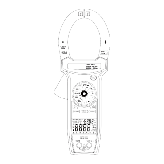
- Page 5 GERÄTEAUFBAU CAT.IV 600V 2000A CAT.III 1500A 1000V TRUE RMS CLAMP METER 2000A 1500A 660A 1500A Hz 660A 0 10 20 30 40 50 60 5 / 67 Version : 2023/06/26...
- Page 6 1. VΩHz%, Spannung, Ohm, Frequenz, Einschaltdauer, Kapazität, Diodeneingangsklemme Dies ist die positive Eingangsklemme für Spannungs-, Ohm-, Frequenz-, Einschaltdauer-, Kapazitäts- und Diodenmessungen. Der Anschluss erfolgt über die rote Prüfleitung. 2. Gemeinsame COM-Klemme Dies ist die negative (Masse-)Eingangsklemme für alle Messarten außer Strom. Der Anschluss erfolgt über die schwarze Prüfleitung.
-
Page 7: Durchführung Von Messungen
Auslöser Drücken Sie den Hebel, um den Transformator zu öffnen. Durch Loslassen des Hebels schließen sich die Backen wieder. Klemmbacken des Transformators Sie nehmen den Wechselstrom oder Gleichstrom auf, der durch den Leiter fließt. Die Markierung "+" auf der Klemmbacke zeigt die Richtung des Gleichstroms in dem geprüften Leiter an, der den Klemmbacken nach vorne und vertikal folgt. -
Page 8: Strommessungen
Strommessungen WARNUNG Dieses Zangenmessgerät wurde entwickelt, um Strommessungen an Schaltungen mit einer maximalen Spannungsdifferenz von 1000 VAC zwischen einem beliebigen Leiter und Erdpotential durchzuführen. Die Verwendung des Zangenmessgeräts für Strommessungen für Schaltungen mit höherer Spannung kann zu elektrischen Schlägen oder zur Beschädigung des zu prüfenden Instruments und/oder der zu prüfenden Ausrüstung führen. -
Page 9: Kapazitätsmessungen
Kapazitätsmessungen 1. Stellen Sie den Funktions-/Bereichsschalter auf die Position " ". 2. Stecken Sie die rote Prüfleitung in die Buchse "VΩ“ und die schwarze Prüfleitung in die Buchse “COM“. 3. Legen Sie die Messfühler an den Kondensator an. Beachten Sie bei der Messung polarisierter Kondensatoren die Polarität. - Page 10 Volt Gleichstrom Auflösung Bereich Genauigkeit Eingangsimpedanz > 100 MΩ 660 mV 0,1 mV ± (0.5% rdg + 2d) 10 MΩ 6,6 V 1 mV ± (0.5% rdg + 2d) 9,1 MΩ 66 V 10 mV ± (0.5% rdg + 2d) 9,1 MΩ...
- Page 11 Widerstand Bereich Auflösung Genauigkeit Offene Schaltung Volt 660Ω 0,1Ω ± (1.0% rdg + 5d) -3,5 V DC 6.600Ω 1Ω ± (1.0% rdg + 5d) -1,1 V DC 66.000Ω 10Ω ± (1.0% rdg + 5d) -1,1 V DC 660.000Ω 100Ω ± (1.0% rdg + 5d) -1,1 V DC 6,6 Mio.Ω...
-
Page 12: Wartung
%Duty Cycle (Einschaltdauer) Genauigkeit ( 5 V Logik) Bereich Auflösung Pulsbreite 5 % bis 95 % >10 μs 0,1 % ± (Messw. 2,0 % +10 d) Frequenzbereich: 5 % bis 95 % ( 40 Hz bis 20 kHz ) Die Messwerte von % DUTY CYCLE werden auf dem Unterdisplay angezeigt. Überlastschutz: 600 V DC oder AC RMS Frequenz Genauigkeit... - Page 13 CONTENTS INTRODUCTION Scope of delivery SAFETY INFORMATION Standards INSTRUMENT LAYOUT HOW TO MAKE MEASUREMENTS Voltage measurements Current measurements Resistance measurements Continuity measurements Diode tests Capacitance measurements Frequency measurements %Duty cycle measurements SPECIFICATIONS MAINTENANCE Cleaning Replacing the battery 13 / 67 Version : 2023/06/26...
-
Page 14: Introduction
INTRODUCTION This manual contains information and warnings which must be followed to ensure safe operation and retain the meter in safe condition. READ "SAFETY INFORMATION" BEFORE USING THE METER. This clamp meter is a handheld 6600-count instrument that is designed for use in the laboratory, field servicing, at home, and any circumstance where high current measurement is required.The clamp meter is built with a design of finger guard which ensures users operating the instrument under a safety situation;... -
Page 15: Standards
Standards Conforms to IEC 61010-1 (EN 61010-1), IEC 61010-2-032 (EN 61010-2-032), CAT III 1000V, CAT IV 600V, Class II, Pollution degree 2, Indoor use. CAT III: Is for measurements performed in the building installation. CAT IV: Is for measurements performed at the sourec of the low-voltage installation. -
Page 16: Instrument Layout
INSTRUMENT LAYOUT CAT.IV 600V 2000A CAT.III 1000V 1500A TRUE RMS CLAMP METER 2000A 1500A 660A 1500A Hz 660A 0 10 20 30 40 50 60 16 / 67 Version : 2023/06/26... - Page 17 1. VΩHz% , Voltage, Ohms, Frequency, Duty cycle, Capacitance, Diode Input Terminal This is the positive input terminal for Voltage, Ohms, Frequency, Duty cycle, Capacitance, Diode measurements.Connection is made to it using the red test lead. 2. COM Common Terminal This is the negative (ground) input terminal for all measurement modes except current.Connection is made to it using the black test lead.
-
Page 18: How To Make Measurements
Trigger Press the lever to open the transformer. When the lever is released, the jaws will close again. Transformer jaws Pick up the AC or DC current flowing through the conductor. The "+" marking on the jaw indicates direction of DC current existing on the conductor being tested which follows forward and vertically with jaws, and reading shown on display is positive. -
Page 19: Current Measurements
Current measurements WARNING These Snap-Arounds are designed to take current measurements on circuits with a maximum voltage difference of 1000VAC between any conductor and ground potential. Using the Snap- Around for current measurements on circuits above this voltage may cause electric shock, instrument damage and/or damage to the equipment under test. -
Page 20: Capacitance Measurements
Capacitance measurements 1. Set the Function/Range switch to the " " position. 2. Connect the red test ldad to the “ VΩ“ jack and the black test lead to the “ COM “ jack. 3. Touch the probes to the capacitor. Observe polarity when measur- ing polarized capacitors. - Page 21 DC Volts Input Impedance Range Resolution Accuracy >100MΩ 660mV 0.1mV ± (0.5% rdg + 2d) 10MΩ 6.6V ± (0.5% rdg + 2d) 9.1MΩ 10mV ± (0.5% rdg + 2d) 9.1MΩ 660V 100mV ± (0.5% rdg + 2d) 9.1M Ω 1000V ±...
- Page 22 Resistance Resolution Range Accuracy Open Circuit Volts 660Ω 0.1Ω ± (1.0% rdg + 5d) -3.5V dc 6.6kΩ 1Ω ± (1.0% rdg + 5d) -1.1V dc 66kΩ 10Ω ± (1.0% rdg + 5d) -1.1V dc 660kΩ 100Ω ± (1.0% rdg + 5d) -1.1V dc 6.6MΩ...
-
Page 23: Maintenance
MAINTENANCE Maintenance consists of periodic cleaning and battery replacement. Dirt or moisture in the terminals can affect readings. Repairs or servicing not covered in this manual should only be performed by qualified personnel. Cleaning ATTENTION To avoid product damage, never use abrosives or liquid solvents. Clean the exterior of the instrument with a dry clean cloth to remove any oil, grease or grime. - Page 24 CONTENU INTRODUCTION Contenu de la livraison INFORMATIONS DE SÉCURITÉ Normes Présentation de l'instrument COMMENT PRENDRE DES MESURES Mesures de tension Mesures de courant Mesures de résistance Mesures de continuité Test de diodes Mesure de capacité Mesure de fréquence Mesures du % de cycle de service SPECIFICATIONS MAINTENANCE Nettoyage...
-
Page 25: Introduction
INTRODUCTION Ce manuel contient des informations et des avertissements qui doivent être suivis rigoureusement afin d'assurer la sécurité du fonctionnement et de maintenir l'appareil en bon état. LIRE LES INFORMATIONS RELATIVES À LA SÉCURITÉ AVANT D'UTILISER CET APPAREIL. Ce multimètre à pince portable 6600 points est conçu pour une utilisation en laboratoire, sur le terrain, à... -
Page 26: Normes
Normes Conforme à CEI 61010-1 (EN 61010-1), CEI 61010-2-032 (EN 61010-2-032), CAT III 1000V, CAT IV 600V, Classe II, Pollution degré 2, Utilisation à l'intérieur. CAT III : pour les mesures réalisées dans un bâtiment en construction. CAT IV : pour les mesures réalisées à la source de l'installation basse tension. CEM : conforme à... -
Page 27: Présentation De L'instrument
Présentation de l'instrument CAT.IV 600V 2000A CAT.III 1500A 1000V TRUE RMS CLAMP METER 2000A 1500A 660A 1500A Hz 660A 0 10 20 30 40 50 60 27 / 67 Version : 2023/06/26... - Page 28 1. VΩHz% , Tension, Ohms, Fréquence, Cycle de service, Capacité, Borne entrée Diode C'est la borne d'entrée positive pour la Tension, Résistance, Fréquence, Cycle de service, Capacité, Borne entrée Diode. Utilisez le câble rouge. 2. Borne commune COM C'est la borne négative (terre) de tous les modes de mesure sauf pour le courant.
-
Page 29: Comment Prendre Des Mesures
10. Autres fonctions Arrêt automatique 1. Arrêt automatique au bout de 30 minutes environ. 2. Après l'arrêt automatique, appuyer sur n'importe quel bouton pour le redémarrer et la mesure prise reste sur l'écran. Désactiver l'arrêt automatique : Appuyer et maintenir le bouton (RANGE) tout en tournant le bouton de la fonction d'arrêt (off) à... -
Page 30: Mesures De Résistance
Mesures de résistance 1. Positionner le bouton Function/Range sur la position " Ω". 2. Couper l'alimentation du circuit à mesurer. Une tension externe sur les composants cause des mesures non valides. 3. Raccorder le cordon rouge à la prise "VΩ" et le cordon noir à la prise "COM". 4. -
Page 31: Specifications
SPECIFICATIONS · Ecran : 6600 points, diagramme à barres analogique de 66 segments. · Polarité : automatique, indication de polarité négative (-). · Indication de dépassement des limites : (OL) ou (-OL) s'affiche. · Indication de pile faible : Le " "... - Page 32 Courant AC (True Moy. quadr.) plage résolution précision (50 ~ 400Hz) 0,1A 660 A 0~660A±(2,0% rdg+10d)50~60Hz 0~660A±(3,0% rdg+10d)61~400Hz 660~1000A±(2,5% rdg+10d)50~60Hz 1500 A 660~1000A±(3,5% rdg+10d)61~400Hz 1000~1500A±(5,0% rdg+10d)50~400Hz Facteur de crête : Retenue de crête : ±(3,0% rdg + 200 dgts) CA couplé...
- Page 33 Résistance Résolution Plage Précision Volts circuit ouvert 0,1Ω 660Ω ± (1,0% rdg + 5d) -3,5V cc 1Ω 6,6 kΩ ± (1,0% rdg + 5d) -1,1V cc 66 kΩ 10Ω ± (1,0% rdg + 5d) -1,1V cc 660 kΩ 100Ω ± (1,0% rdg + 5d) -1,1V cc 6,6 MΩ...
-
Page 34: Maintenance
MAINTENANCE La maintenance se résume à un nettoyage périodique et au remplacement de la pile. La saleté ou l'humidité des bornes peuvent affecter les mesures. Les réparations ou l'entretien qui ne sont pas abordés dans ce manuel doivent être réalisés uniquement par des ouvriers qualifiés. - Page 35 SOMMARIO INTRODUZIONE Materiale compreso nella fornitura INFORMAZIONI DI SICUREZZA Norme LAYOUT DELLO STRUMENTO COME ESEGUIRE LE MISURAZIONI Misura della tensione Misura della corrente Misura della resistenza Misura della continuità Test dei diodi Misura della capacitanza Misura della frequenza %Misura del Ciclo di lavoro SPECIFICHE MANUTENZIONE Pulizia...
-
Page 36: Introduzione
INTRODUZIONE Il presente manuale contiene informazioni e avvertenze che devono essere seguite per garantire un funzionamento sicuro e per mantenere il multimetro in condizioni di sicurezza. LEGGERE LE "INFORMAZIONI DI SICUREZZA" PRIMA DI USARE LO STRUMENTO. Questa pinza amperometrica è un multimetro portatile da 6600 conteggi progettato per l'uso in laboratorio, durante interventi di manutenzione sul campo, a casa e in qualunque altra circostanza in cui sia necessario eseguire misurazioni di correnti elevate. -
Page 37: Norme
Norme Conforme a IEC 61010-1 (EN 61010-1), IEC 61010-2-032 (EN 61010-2-032), CAT III 1000V, CAT IV 600V, Classe II, Grado di inquinamento 2, Uso interno. CAT III: per misurazioni eseguite nell'impiantistica. CAT IV: per misurazioni eseguite presso la sorgente di impianti a bassa tensione. EMC: Conforme a EN 61326-1: 2006 Conforme alle direttive UE pertinenti I simboli usati nello strumento sono:... -
Page 38: Layout Dello Strumento
LAYOUT DELLO STRUMENTO CAT.IV 600V 2000A CAT.III 1500A 1000V TRUE RMS CLAMP METER 2000A 1500A 660A 1500A Hz 660A 0 10 20 30 40 50 60 38 / 67 Version : 2023/06/26... - Page 39 1. VΩHz% , Tensione, Ohm, Frequenza, Ciclo di lavoro, Capacitanza, Terminale Ingresso Diodo Questo è il terminale d'ingresso positivo per la misurazione di tensione, ohm, frequenza, ciclo di lavoro, capacitanza e diodo. Il collegamento è realizzato tramite il puntale di prova rosso. 2.
- Page 40 1. Pulsante PEAK ± (Picco) 1. Memorizza il valore di picco+ o picco- in una misurazione. Può essere utilizzato con la misura della corrente alternata e della tensione alternata. Se viene premuto per un tempo >2 sec, la funzione PEAK (Picco) entrerà nella Modalità di calibrazione, l'LCD indicherà "CAL"...
-
Page 41: Come Eseguire Le Misurazioni
COME ESEGUIRE LE MISURAZIONI Prima di eseguire qualsiasi misurazione leggere le precauzioni di sicurezza. Esaminare sempre lo strumento e gli accessori utilizzati con lo stesso per rilevare l'eventuale presenza di danni, contaminazioni (sporco eccessivo, grasso, ecc.) e difetti. Esaminare i puntali di prova per verificare che l'isolamento non sia fessurato o logoro e assicurarsi che le spine di prova si inseriscano perfettamente nei terminali dello strumento. -
Page 42: Misura Della Resistenza
Misura della resistenza 1. Impostare l'interruttore di Funzione/Portata nella posizione " Ω ". 2. Rimuovere l'alimentazione dal circuito sotto test. La tensione esterna nei componenti provoca una lettura non valida. 3. Connettere il puntale di prova rosso al jack " VΩ " e il puntale di prova nero al jack " COM ". -
Page 43: Specifiche
SPECIFICHE · Display: 6600 conteggi, grafico a barre analogico da 66 segmenti. · Polarità: Automatica, indicazione della polarità negativa (-). · Indicazione di fuori scala: sono visualizzati (OL) o (-OL). · Indicazione batteria scarica: quando viene visualizzato il simbolo " "... - Page 44 Corrente AC (Vero Valore Efficace-T.RMS) Portata Risoluzione Precisione (50 ~ 400 Hz) 0,1 A 660 A 0~660A±(2,0% letture+10cifre)50~60Hz 0~660A±(3,0% letture+10cifre)61~400Hz 660~1000A±(2,5% letture+10cifre)50~60Hz 1500 A 660~1000A±(3,5% letture+10cifre)61~400Hz 1000~1500A±(5,0% letture+10cifre)50~400Hz Fattore di cresta: Mantenimento del picco (Peak Hold): ±(3,0% letture + 200 cifre) Vero valore efficace accoppiato AC specificato dal 5% al 100% della portata FREQUENZA Portate: 50Hz ~ 1kHz.
-
Page 45: Manutenzione
%Ciclo di lavoro Portata Risoluzione Larghezza impulso Precisione ( 5 V logica) μs da 5% a 95% 0,1% >10 ±(2,0% letture+10cifre) Gamma di frequenze: da 5% a 95% (da 40 Hz a 20 kHz) Le letture delle misurazioni % DUTY CYCLE (Ciclo di lavoro) saranno mostrate sul sotto display. - Page 46 ÍNDICE INTRODUCCIÓN Volumen de suministro INFORMACIÓN DE SEGURIDAD Normas DISEÑO DEL APARATO CÓMO HACER MEDICIONES Mediciones de tensión Mediciones de corriente Mediciones de resistencia Mediciones de continuidad Ensayos de diodos Medición de capacidad Medición de frecuencia Medición de tiempo de funcionamiento (%) DATOS TÉCNICOS MANTENIMIENTO Limpieza...
- Page 47 INTRODUCCIÓN Este manual contiene información y advertencias que se deben seguir a fin de garantir un manejo seguro y que el multímetro se mantenga en buen estado. LEA “INFORMACIÓN DE SEGURIDAD” ANTES DE USAR EL MULTÍMETRO. Este multímetro con pinza es un instrumento portátil de 6600 puntos diseñado para uso en laboratorio, trabajo de campo, uso doméstico y, en general, cualquier circunstancia en que se necesario realizar una medición de alta corriente.
- Page 48 Normas Conforme con las normas IEC 61010-1 (EN 61010-1), IEC 61010-2-032 (EN 61010-2-032), CAT III 1000V, CAT IV 600V, clase II, grado de contaminación 2, uso en interior. CAT III: para mediciones realizadas en la instalación de edificios. CAT IV: para mediciones realizadas en la fuente de la instalación de baja tensión. CEM: conforme con la norma EN 61326-1:2006 Conforme con las directivas de la UE aplicables En este instrumento se utilizan los símbolos siguientes:...
- Page 49 DISEÑO DEL APARATO CAT.IV 600V 2000A CAT.III 1500A 1000V TRUE RMS CLAMP METER 2000A 1500A 660A 1500A Hz 660A 0 10 20 30 40 50 60 49 / 67 Version : 2023/06/26...
- Page 50 1. VΩHz% , Terminal de entrada para tensión, resistencia eléctrica, frecuencia, tiempo de funcionamiento, capacidad, diodo Este es el terminal de entrada positivo para mediciones de tensión, resistencia eléctrica, frecuencia, tiempo de funcionamiento, capacidad y diodo. La conexión se realiza usando el cable de ensayo rojo. 2.
- Page 51 1. Botón PEAK ± 1. Registra los valores pico máximo y mínimo en una medición. Se usa con mediciones de tensión alterna y corriente alterna. Si se mantiene pulsado durante más de 2 segundos, la función PEAK entrará en modo de calibración, en la pantalla se mostrará "CAL" y el buffer interno recordará...
- Page 52 Mediciones de corriente ADVERTENCIA Estas pinzas están diseñadas para realizar mediciones de corriente en circuitos con una diferencia de tensión máxima de 1000 V CA entre cualquier conductor y el potencial de tierra. Usar la pinza para realizar mediciones de corriente en circuitos que superen esta tensión puede provocar descargas eléctricas, así...
- Page 53 Medición de capacidad 1. Sitúe el selector de función/rango en la posición " ". 2. Conecte el cable rojo en el conector "VΩ" y el negro en el conector "COM". 3. Aplique las sondas al condensador. Tenga en cuenta la polaridad al medir condensadores polarizados.
- Page 54 Tensión en CC Rango Resolución Precisión Impedancia de entrada > 100MΩ 660 mV 0,1 mV ± (0,5 % lec. + 2 d.) 10MΩ 6,6 V 1 mV ± (0,5 % lec. + 2 d.) 9,1MΩ 66 V 10 mV ± (0,5 % lec. + 2 d.) 9,1MΩ...
- Page 55 Resistencia Rango Resolución Precisión Tensión de circuito abierto 0,1Ω 660Ω ± (1,0 % lec. + 5 d.) -3,5 V CC 6,6 kΩ 1Ω ± (1,0 % lec. + 5 d.) -1,1 V CC 10Ω 66 kΩ ± (1,0 % lec. + 5 d.) -1,1 V CC 660 kΩ...
- Page 56 MANTENIMIENTO El mantenimiento consiste en una limpieza periódica y la sustitución de la pila. La presencia de suciedad o humedad en los terminales puede afectar a las lecturas. Las reparaciones o intervenciones de servicio no especificadas en este manual deben ser realizadas exclusivamente por personal cualificado.
- Page 57 TARTALOMJEGYZÉK BEVEZETÉS Szállított alkatrészek BIZTONSÁGI ELŐÍRÁSOK Szabványok KÉSZÜLÉK ELRENDEZÉSE MÉRÉS Feszültségmérés Ampermérés Ellenállás mérése Szakadásmentesség mérése Diódák ellenőrzése Kapacitív ellenállás mérése Frekvencia mérése %Működési ciklus mérése MŰSZAKI ADATOK KARBANTARTÁS Tisztítás Elemcsere 57 / 67 Version : 2023/06/26...
- Page 58 BEVEZETÉS Ez az útmutató olyan információkat és figyelmeztetéseket tartalmaz, amelyeket a biztonságos működés és a mérőeszköz biztonságos állapotának megtartása érdekében feltétlenül be kell tartani. A MÉRŐESZKÖZ HASZNÁLATA ELŐTT OLVASSA EL A "BIZTONSÁGI ELŐÍRÁSOKAT". A szorításmérő egy olyan 6600 impulzusszámú kézi berendezés, amelyet olyan laboratóriumi, terepi, otthoni, illetve bármely egyéb helyre terveztek, ahol árammérés szükséges.
- Page 59 Szabványok Megfelel a következő szabványok előírásainak: IEC 61010-1 (EN 61010-1), IEC 61010-2-032 (EN 61010-2-032), CAT III 1000 V, CAT IV 600V, II osztály, 2 szennyezési fokozat, beltéri használat. III. kat. épületen belüli szerkezetek mérésére. IV. kat. kisfeszültségű szerkezetek közelében végzett mérésekhez. EMC: megfelel az EN 61326-1: 2006 szabvány előírásainak Megfelel a vonatkozó...
- Page 60 KÉSZÜLÉK ELRENDEZÉSE CAT.IV 600V 2000A CAT.III 1500A 1000V TRUE RMS CLAMP METER 2000A 1500A 660A 1500A Hz 660A 0 10 20 30 40 50 60 60 / 67 Version : 2023/06/26...
- Page 61 1. V Ω Hz% , Feszültség, Ohm, Frekvencia, Működési ciklus, Kapacitív ellenállás, Dióda Bemeneti érintkező Ez a pozitív bemeneti csatlakozó a feszültség, az ohm, a frekvencia, a működési ciklus, a kapacitív ellenállás, a dióda méréséhez. A csatlakoztatáshoz használja a piros vezetéket. 2.
- Page 62 10. Egyéb funkciók Automatikus kikapcsolás 1. Automatikus kikapcsolás: kb. 30 perc után. 2. Az automatikus kikapcsolást követően a berendezés bármelyik gomb megnyomásával visszakapcsolható, és a mért érték ismét látható a kijelzőn. Az automatikus kikapcsolás funkció letiltása: Tartsa lenyomva a (TARTOMÁNY) gombot, és a mérőeszköz bekapcsolásához közben állítsa a forgókapcsolót KI állásból bármelyik másik állásba.
- Page 63 Ellenállás mérése Ω 1. Állítsa a Funkció/Tartomány kapcsolót " " helyzetbe. 2. Kapcsolja ki a mérni kívánt áramkör feszültségét. Az egységeken lévő külső feszültség hamis eredményt okoz. Ω 3. Csatlakoztassa a piros mérőkábelt a "V " csatlakozóhoz, a feketét pedig a "COM" csatlakozóhoz.
- Page 64 MŰSZAKI ADATOK - Kijelző: 6600 karakterből, 66 szegmensből álló analóg oszlopdiagram. - Polaritás: Automatikus (-) negatív polaritásjelzés. - Túllépés jelzés: (OL) vagy (-OL) látható. - Alacsony akkumulátorszint jelzés: Ha az akkumulátor töltési szintje az üzemi szint alá csökken, a kijelzőn " "...
- Page 65 AC áramerősség (Valós RMS) Tartomány Felbontás Pontosság (50 ~ 400 Hz) 660 A 0,1 A 0~660 A ± (2,0% rdg+10d )50~60 Hz 0~660 A ± (3,0% rdg+10d) 61~400 Hz 1500 A 660~1000 A ± (2,5% rdg+10d) 50~60 Hz 660~1000 A ± (3,5% rdg+10d) 61~400 Hz 1000~1500 A ±...
- Page 66 %Működési ciklus Tartomány Felbontás Impulzusszélesség Pontosság ( 5 V logikai) >10μs 5% - 95% 0,1% ± (2,0% rdg +10d) Frekvenciatartomány 5% - 95% ( 40 Hz - 20 kHz ) A MÜKÖDÉSI CIKLUS % értéke az alkijelzőn látható. Túlterhelés- védelem: 600 V DC vagy AC rms Frekvencia Indítási szint Tartomány...
- Page 67 67 / 67 Version : 2023/06/26...