Advertisement

READ OPERATING MANUAL BEFORE OPERATING TRAP
All personnel required to operate the trap or load targets into the magazine, should read this instruction manual and be trained by someone knowledgeable as to the safe operation of the equipment.
ASSEMBLY INSTRUCTIONS / SET UP
- Remove trap from packaging.
- Inspect packaging and make sure there is no damage. If any damage has occurred during shipping, contact the freight carrier and Atlas Trap Co.
- Always stand at rear of trap, never on either side or in front.
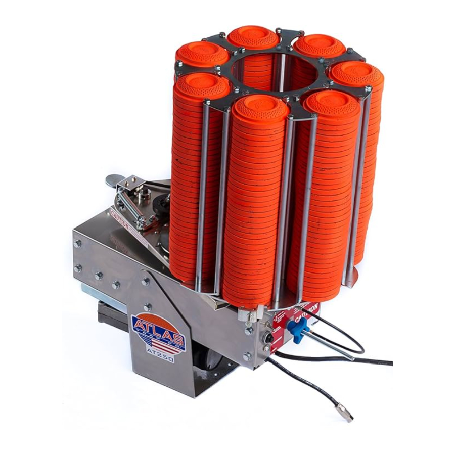
- On the rear of the trap you will find a caution decal. On this caution decal you will find a toggle switch, firing button, 30-amp circuit breaker and a plug-in for the release mechanism. Make sure the toggle is switched down. Even though toggle is in the down position motor will still operate if firing button is pressed. DO NOT PRESS FIRING BUTTON DURING SET UP!
- Plug in release cord at rear of trap.
- Adjust elevation by loosening 4 adjusting bolts (2 on each side of machine where the base attaches to the frame). Set elevation to desired angle and retighten the 4 adjusting bolts.
- Mount trap to sturdy base.
- Load 108mm targets into magazine.
- Before connecting to battery, read, understand all safety instructions noted in this guide.
- Stand at rear of trap and stay clear of throwing arm. Attach battery terminals to battery. Flip the toggle switch to the up position. Trap will cock at this time. Always remember, when trap is connected to battery, trap is cocked and ready to fire. When trap is disconnected from battery, it is still in the cocked position. See safety precautions and de-cocking procedures.
BATTERIES
- You must use a 12-volt deep cycle marine type battery.
- Keep battery fully charged, low battery voltage may cause excessive motor heat, slow cocking time, blowing of fuse and early motor failure, etc.
- Always inspect battery clips on trap, keep them clean.
- Charge battery when not in use with a trickle charger.
- Trap is polarity protected.
TARGET ROLLER ADJUSTMENT
- Before adjusting rollers make sure trap is de-cocked and disconnected from battery. Rollers are pre-adjusted for White Flyer targets. They should not need re-adjusted for other brands of targets. However, should you need to re-adjust for any reason, follow the steps below.
- Make sure that the bottom of the roller does not come in contact with the clay that is directly set on the aluminum magazine plate (the clay on the bottom of the stack). To adjust rollers you will need 2 – ¾" end wrenches. To adjust roller up, loosen top ¾" nut. Then, by hand, move bottom ¾" nut toward roller. Once you have the desired roller height, retighten top nut down to the bottom ¾" nut. To adjust roller down, loosen top ¾" nut until roller is in desired position. Hold this top nut so that it does not move and retighten bottom ¾" nut.
- If the roller is set too high, this will allow 2 targets to drop and result in breakage of target. If roller is too low, the first target will not drop and it will break once the trap cycles
- Target roller adjustment is critical. If the rollers are not adjusted properly, the trap will not operate properly.
RELOADING MAGAZINE
- When trap runs out of targets, turn toggle switch to the down position, unhook from battery and reload magazine.
- Excessive dry firing of trap puts a heavy load on trap components.
ATA/OSCILLATING BASE MOUNTING INSTRUCTIONS
(If you purchased an ATA/oscillating base you will need to follow these instructions)
- Remove 2-3/8" bolts from top plate of ATA/oscillating base. You will reuse these bolts to secure trap to ATA/oscillating base.
- Set trap on top of ATA/oscillating and secure in the middle 2 holes with supplied bolts.
- When Trap is mounted to oscillating base it is ready to be used. Make sure the trap and oscillating base are clear from any obstructions that could bind either the trap or the oscillator. Hook positive (red) battery clip to a Deep-cycle marine battery. There is not a negative battery clip (black). ATA base gets negative charge via trap.
WOBBLE BASE MOUNTING INSTRUCTIONS
(If you purchased a wobble base you will need to follow these instructions)
Your new Atlas wobble base will allow your Atlas Trap to throw targets in a number of different directions, both vertical and horizontal. If your Atlas Trap did not arrive mounted to the wobble base, there are a few steps you will need to take to mount the two items together. Inspect the packaging for damage in transit and remove the wobble base from its box.
- You will need to remove your trap from its cradle and remount into the wobble base cradle. To do this, remove the 4 bolts (and nut plates from inside the trap) directly above the Atlas logo decal on your trap (you will not reuse these with the wobble base). The trap will lift directly out of its cradle.
- Remove the top 2 pivot bolts, spacers and nuts that came with the wobble base. You will reuse these to mount the trap.
- Place trap inside the wobble cradle. You will reuse the 2 pivot bolts, spacers and nuts. Place the pivot bolt through the spacer then through the top pivot hole on the wobble base and the trap. From the inside of the trap, place the nut on the pivot bolt and tighten. You will not use the bottom hole above the logo decal or the nut plates.
- The vertical gear motor has a linkage and an "L" bracket that needs to be mounted to the trap. The bracket mounts to the bottom corner of the trap. You will need to remove the 5/16" bolt from the bottom of the trap and mount the bracket to this hole. The hole should be directly above the linkage and gear motor.
There are 2 toggle switches on the base, one if for the horizontal movement and the other for the vertical movement. You can run these switches independently for your desired presentation. The wobble base only has a positive (red) battery cable. The base receives its negative feed from the case of the trap.
WIRELESS REMOTE
1 – 12 Volt Transmitter
1 – 12 Volt Receiver LT-100
To connect the wireless remote to your Atlas Trap:
- Find a suitable location to mount the receiver.
- Plug in male adapter at rear of trap.
- Connect red clip to positive terminal on battery. Connect black clip to negative terminal on battery. You may connect to the same battery that powers the trap.
- The receiver is now in ready-mode.
To use transmitter:
- Once receiver is connected to trap, trap and receiver are connected to battery, transmitter is ready to use.
- When ready to fire, press button on transmitter until trap fires. Do not hold button down. This will cause the trap to continuously fire and break targets.
***Transmitter is NOT waterproof. Approximate range on transmitter is 100 yards line of sight.
CART ASSEMBLY
Tools required:
1 – 9/16" wrench
1 – 5/32" Allen wrench

- Remove cart from packaging.
- Remove axel from inside the long cart tongue.
- Remove both battery box bolts and remove the hitch tongue that is inside the long cart tongue.
- Turn this hitch tongue 180°. You want the small hole in hitch tongue extended outside of the long cart tongue.
- The holes in the long tongue, battery box and hitch tongue will all line-up. Reinstall the battery box bolts (the ones you removed first) through all 3 items.
- Place axel through axel housing and mount tires on axel. Use the 5/8" set collars to hold the tires on.
- Mount trap on axel housing and tongue with the 4-supplied bolts.
For carts that have an ATA/oscillating base: skip step 7 and proceed to step 8.
- Mount 12"x 2" strap to long cart tongue using supplied hardware. Align center hole of strap to center hole on long cart tongue (between battery box and axel housing).
- You are now ready to set trap and ATA/oscillating base onto the cart. Trap should mount directly down on the axel housing. For rear of trap, use 3 washers (supplied) between the strap and the ATA/oscillating base, on each side, to create proper spacing. Use ¼" bolts (supplied) in all 4 corners of base to secure.
- Trap should throw away from battery box.
SAFETY PRECAUTIONS
- Stand to rear of trap. Stay clear of throwing arm path, which is 360°. If toggle is in the up position, trap will immediately cock. If toggle is in the down position, trap can still fire if firing mechanism is pressed.
- Mount trap only to secure fixture. Throw targets only in a safe direction. Know target path as well as shooters zone of fire.
- All spectators, bystanders, operators and shooters stand behind trap, not to either side or front. Wear safety glasses. Never allow children near trap.
- Approach trap only from rear, not from front or either side.
- Never allow persons less than 18 years of age to operate or approach trap. Never allow persons to operate trap who have not read and understand information contained in this instruction manual.
- Never leave cocked trap or firing button unattended. Always un-cock trap after use and before moving.
- Targets may be thrown in rapid succession. However, continuous cycling may cause motor to overheat. Do not allow motor to overheat!
- Never adjust, tamper or transport trap while cocked or connected to battery. Remember if trap is disconnected from battery it is still cocked unless it is un-cocked by you.
- To partially un-cock trap, follow steps 1-4.
Step 1. Switch toggle to down position.
Step 2. Tap firing button.
Step 3. Remove both battery clips from battery immediately following firing of trap.
OR, simply remove 3/8" nut that is attached to spade bolt at rear of trap and manually rotate throwing arm counter-clockwise until throwing arm is straight out front of trap. - Never touch or push on throwing arm. Touching or pushing on throwing arm could cause trap to fire without warning. Also, pushing on throwing arm will cause crank shaft to crash into gearbox gear and will void warranty.
TROUBLE SHOOTING
PROBLEM: Trap will not cock or blowing fuses.
SOLUTION: Battery is dead or weak. Charge battery or replace. Check wire to make sure that it is not broken at clip. It is not good to operate trap on a weak battery.
PROBLEM: Trap will not feed targets. Trap breaks targets
SOLUTION: Make sure targets are not moist. Old targets draw moisture. See knife adjustment.
PROBLEM: Target has short throwing distance.
SOLUTION: Spring is too loose. Spring may have lost temper, if so, replace spring.
PROBLEM: Excessive target breakage.
SOLUTION: Allow throwing arm to completely stop before holding down on the firing button.
WARRANTY INFORMATION
TRAP: 5 year Limited Warranty against defects in material and workmanship.
CLUTCH: The Dura-Clutch™ - Lifetime Limited Warranty against defects in material and workmanship.
WARRANTY applies to original purchaser with original receipt.
Equipment, with factory inspection, that reveals to be defective in material or workmanship within the terms of this warranty shall be replaced or repaired at no charge. Equipment that reveals to be abused, misused, or damaged by exposure, water, or lightning will not be covered under warranty. But, will be repaired at a reasonable charge to customer. Gears in motor are not covered under warranty. However, gear motors that are denied warranty will be replaced at a 50% reduction of current published price. Mainsprings are not covered under warranty.
ATLAS TRAP CO, INC.
14264 SW 50TH
BENTON, KS 67017
TEL 316-778-2002
FAX 316-778-2001
WWW.ATLASTRAPS.COM

Documents / Resources
References
Download manual
Here you can download full pdf version of manual, it may contain additional safety instructions, warranty information, FCC rules, etc.
Advertisement
Thank you! Your question has been received!
Need Assistance?
Do you have a question about the AT 250 that isn't answered in the manual? Leave your question here.