Control4 C4-8AMP1-B - 4-Zone Amplifier Manual
- Installation and setup manual (3 pages) ,
- Specifications (2 pages) ,
- Installation and setup manual (2 pages)
Advertisement
- 1 Supported Models
- 2 What's in the Box
- 3 Additional Resources
- 4 Requirements and Specifications
- 5 Features and Benefits
- 6 About the 4-Zone Amplifier
- 7 Install the 4-Zone Amplifier
- 8 View Output Assignments
- 9 Manage Amplifier Output Zones
- 10 View Network Settings
- 11 Set Display Preferences
- 12 Options Available in Composer
- 13 Documents / Resources
Supported Models
This installation guide covers this amplifier model:
- C4-8AMP1-B: 4-Zone Amplifier
What's in the Box
The following hardware and software is required and included in your Control4 4Zone Amplifier box.
- Control4 4-Zone Amplifier
- IEC power cord
- This document
Additional Resources
The following resources are available:
- Your Control4-authorized reseller
- Control4 Web Site: http://www.control4.com/
Requirements and Specifications
- Ensure that your home network wiring is in place before starting your system setup. The 4-Zone Amplifier is controlled through 10/100 Ethernet networking.
- Device must not be installed in a cabinet that is smaller than 20" wide x 20" deep x 10" high.
Table 1. 4-Zone Amplifier
| C4-8AMP1-B | 4-Zone Amplifier |
| Communications: | Ethernet 10/100 networking |
| Connections: | 4 stereo inputs, two of which can be digital 4 sets of amplified speaker outputs |
| Dimensions: | 4" x 17" x 16" |
| Display: | LCD screen |
| Power requirements: | 100-240 VAC, 50-60 Hz |
| Shipping weight: | approximately 16 lbs |
Features and Benefits
- Receives up to four stereo inputs with full audio switching on inputs.
- Outputs four stereo class D amplified channels at 60 W per channel at 8 ohms or at 120 W per channel at 4 ohms (not all channels driven simultaneously).
- Adjustable gain, treble, and bass for each zone
- Master Volume Control for all outputs
- Device chassis is two standard rack spaces and rack mountable using three standard rack spaces configuring to EIA 19" rack standards. The optional Control4 Rack Mount Kit (C4-3URMK-B) provides 1/2 U spacing above and below the chassis. If the Control4 Rack Mount Kit is not used, allow ½ rack space above and below the chassis for ventilation.
- Communicates via Ethernet 10/100 networking.
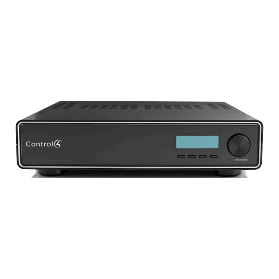
About the 4-Zone Amplifier
Front and Back Views

- Front Display—LCD for displaying or setting 4-Zone Amplifier settings, navigating system menus, viewing or modifying audio source routing and zone settings for gain, bass, and treble, or viewing zone activity.
- Select Dial—For scrolling through list items and options displayed on the LCD. Press to make selections.
- Buttons—For accessing menu options displayed on the LCD.
- Ethernet Port—RJ-45 for a 10/100 BaseT Ethernet connection
- Audio Inputs 1-4—Jacks for up to four audio sources. Inputs 1 and 3 can be set up for analog or digital sources. Inputs 2 and 4 are for analog sources only.
- Amplifier Outputs 1-4—5-way binding post pair for up to four stereo class D amplified zones
- Power Plug Port—For use with a standard IEC equipment power cord. Use the supplied power cord or ensure the power cord you are using is at least 18 AWG or larger.
Install the 4-Zone Amplifier
This device operates as part of the Control4 home system, which requires physical connections and logical connections to function as designed.

Connecting speaker wires or input cables while the 4-Zone Amplifier is powered, may cause shock and could damage the amplifier. Unplug the power cord before making connections.

Do not bridge outputs. The outputs on the C4-8AMP1-B cannot be bridged. Do not connect black terminals together or to ground. The black terminals are not at ground potential; connecting them together or to ground can damage the amplifier.
- Connect up to four audio source devices (such as a controller, tuners, or CD or tape players) to the audio input jacks.
Note: Inputs 1 and 3 can be set up for analog or digital sources. - Connect speakers to the audio output jacks. Tighten the binding posts to ensure a good electrical connection to the speaker wires (even if you are using banana plugs).
- Use a standard 10/100 Base T Ethernet cable to connect the Ethernet port on the amplifier to your network.
- Connect the power cord provided to the back of the amplifier and to the power outlet. Once the power cord is connected, the amplifier should power up.
Set Up Logical Connections
You must configure the 4-Zone Amplifier in the Composer project in order to control, navigate, and use the amplifier as designed.
Create logical connections in Composer. For instructions, refer to the Control4 Composer Pro User Guide.
Set Network Settings
The 4-Zone Amplifier, by default, uses DHCP to obtain a network IP address. If the local area network does not support DHCP, you can configure the switch to use a Static IP address instead:
- Press Config.
- Using the Select Dial, scroll down to Network and press the Select Dial to view the Network menu.
![]()
- Press the Select Dial to edit your setting. Rotate the dial to choose Static IP.
![]()
- Press OK (or press the Select Dial).
- Edit the IP, GW, and MK fields for the Static IP network: Use the Select Dial to select a line, then press the dial. (Scroll down to see GW and MK.)
![]()
Use the Select Dial scroll the number up or down and edit as needed, then press the Select Dial to move to the next field within the number.


View Output Assignments
Once you complete the physical connections and logical connections (in Composer), you can view or change your setup in the 4-Zone Amplifier front display.
When you first power up the 4-zone amplifier, a System Status screen similar to the following one appears momentarily.

The System Status screen is then replaced by the In to Out Assignments screen. The screen shows 4 output zones and any assigned input sources (such as Input 1 as shown in the following screen).

The menu buttons on the front panel provide access to the following screens:
- Audio: Displays audio settings and allows some control of inputs, outputs, and tone controls.
- Config: Displays current settings and allows for some configuration of the LCD and Network settings and reset to factory defaults.
Note: After leaving the Audio or Config menu and returning to the In to Out Assignments screen, you may need to wait for the screen to load before selecting another menu.
Manage Amplifier Output Zones
View or Change Output Settings
Change Source Settings
To view or change source settings:
- On the In to Out Assignments screen, press the Audio button and select Outputs.
The output settings of the default output screen (the last output screen accessed) are displayed.
![]()
- Input (number): If an input source is assigned, the Input source number is displayed
- Gain (setting): Supported range: 0 - 100 (-100 to 0 dB)(1 - 4) or can be changed to OFF for no connection.
Note: The gain setting cannot be larger than the volume limit. - Limit: Set a volume limit. Options are 0 - 100 or off.
- Exit: Returns to the In to Out Assignments screen.
- (Conditional) View a different output number: If the output screen that you want to view is not displayed, use the - or + button to select a different screen.
- (Optional) Change an output setting:
- Using the Select Dial, highlight the Input, Gain, or Limit field and then press the Select Dial to enter edit mode.
- Turn the Select Dial (or use the Up/Down buttons) to set a new number and then press the dial to save the setting.
- Input: Off, 1-4
- Limit: Off, 0-100

View Tone Settings
To view tone settings:
- From the Audio screen, press Tone Settings.
- View the following settings:
- Bass Gain: Supported range: -12 to +12 dB
- Treb Gain: Supported range: -12 to +12 dB
- Press the Select Dial to enter Edit mode.
- Rotate the dial to change the setting. Press the dial to save the new setting and exit the Edit mode. To exit without saving, choose Cancel.
View or Change Input Settings
- On the In to Out Assignments screen, press the Audio button and select Inputs.
- From the Output screen, press the Inputs button to display the assigned Input screen. From here you can change the Gain setting and view whether digital is enabled or disabled (inputs 1 and 3 only).
- Outputs: To toggle back to the Output screen
- Exit: To return to the In to Out Assignments
- (Optional) Change the Gain on an input source in order to balance unequal source levels by reducing the levels of any louder sources: Use the Select Dial to highlight, select, and change this setting. This sets the input attenuation. Supported range is -6 to 0 dB.
- Use the - or + button to switch to a different input zone.
- Press the Exit button to return to the In to Out Assignments screen.
View Network Settings
- On the In to Out Assignments screen, press the Config button and select Network.
- To edit these settings, see "Set Network Settings".
- Press the Back button to return to the In to Out Assignments screen.
Set Display Preferences
To set your viewing preferences for the front display:
- On the In to Out Assignments screen, press the Config button and select LCD.
![]()
- Use the buttons or the Select Dial to choose a setting to change: Once you press the Select button (or press the dial), you enter Edit mode.
- In Edit mode, use the buttons or Select Dial to change the highlighted setting. Press the OK button (or press the dial) to save the change and exit Edit mode.
- Brightness: Supported range: 0 to 100
- Contrast: Supported range: 0 to 100
- Backlight: Supported settings are
- Off (always off)
- 5 to 90 seconds (default is 60 seconds)
- On (always on)
- Press the Exit button to return to the In to Out Assignments screen.

Options Available in Composer
The following options are available in Composer:
- Volume curve: The volume curve default follows the Control4 speaker-point volume curve. The volume curve can be changed to match the V1 curve using Composer.
- 5-band parametric equalizer: A 5-band parametric equalizer is available in Composer for tighter output control.
- Inputs Locked: Locks all Inputs to their corresponding Outputs (1:1, 2:2, 3:3, 4:4).
- Power Save Enable: The Amp will go into a power saving stand by mode when not in use

Documents / Resources
References
Download manual
Here you can download full pdf version of manual, it may contain additional safety instructions, warranty information, FCC rules, etc.
Advertisement
Thank you! Your question has been received!


Need Assistance?
Do you have a question about the C4-8AMP1-B that isn't answered in the manual? Leave your question here.