Table of Contents
Advertisement
Quick Links
MITSUBISHI HEAVY INDUSTRIES THERMAL SYSTEMS, LTD.
2-3, Marunouchi 3-chome, Chiyoda-ku, Tokyo, 100-8332, Japan
http://www.mhi-mth.co.jp/en/
MITSUBISHI HEAVY INDUSTRIES - MAHAJAK AIR CONDITIONERS CO., LTD.
220 Lad Krabang Industrial Estate Free Zone 3, Soi Chalongkrung 31, Kwang Lamplatiew,
Khet Lad Krabang, Bangkok 10520, Thailand
Tel : +66-2-326-0401
Fax : +66-2-326-0419
http ://www.maco.co.th/
RMA012A105G_D_Cover.indd 1
RMA012A105G_D_Cover.indd 1
USER'S MANUAL
&
INSTALLATION MANUAL
AIR-CONDITIONER
SRK19CSS-S3
SRK25CSS-S3
Thank you for purchasing a MITSUBISHI HEAVY INDUSTRIES THERMAL SYSTEMS, LTD. Air-Conditioner.
To get the best long-lasting performance, read and follow this User's Manual carefully before using your air-conditioner.
After reading, please store the Manual in a safe place and refer to it for operational questions or in the event of any irregularities.
This air-conditioner is intended for domestic use.
* Characteristics of the Air-conditioner may vary on some models.
This Air-conditioner for use R410A only
ORIGINAL INSTRUCTIONS
USER'S MANUAL
INSTALLATION MANUAL
RMA012A105G D
202004
03/04/2020 09:10:22
03/04/2020 09:10:22
Advertisement
Chapters
Table of Contents

Related Manuals for Mitsubishi Heavy Industries SRK19CSS-S3


Summary of Contents for Mitsubishi Heavy Industries SRK19CSS-S3
- Page 1 SRK25CSS-S3 MITSUBISHI HEAVY INDUSTRIES THERMAL SYSTEMS, LTD. Thank you for purchasing a MITSUBISHI HEAVY INDUSTRIES THERMAL SYSTEMS, LTD. Air-Conditioner. 2-3, Marunouchi 3-chome, Chiyoda-ku, Tokyo, 100-8332, Japan To get the best long-lasting performance, read and follow this User’s Manual carefully before using your air-conditioner.
-
Page 2: Table Of Contents
USER’S MANUAL contents Safety precautions .........................2 Choice of operations and features ....................4 Name of each part and its function ....................5 Operation and indication section for remote control ..............8 AUTO mode operation procedure ....................9 Temperature adjustment during AUTO ..................9 About FAN SPEED ........................9 COOL/DRY/FAN mode operation procedure ................10 Air-conditioner operating conditions ..................10 Air fl... -
Page 3: Safety Precautions
Safety precautions Before starting to use the system, please read these “Safety precautions” carefully. When you have read this instruction manual, please keep it without missing. Symbols which appear frequently in the text have the following meaning: Observe instructions with Strictly prohibited Provide positive earthing great care... - Page 4 ❚ OPERATION PRECAUTIONS WARNING Do not expose yourself to the cooling air for a long period. This could affect your physical condition and cause health problems. Do not insert anything into the air inlet. This may cause injury, as the internal fan rotates at high speed. The appliance is not intended for use by persons (including children) with reduced physical, sensory or mental capabilities, or lack of experience and knowledge, unless they have been given supervision or instruction concerning use of the appliance by a person responsible for their...
-
Page 5: Choice Of Operations And Features
Choice of operations and features Choice of operations Page 10 Page 10 COOL Cooling by extracting heat from the room. Drying by extracting damp from the room. Functioning of microcomputer depends on setting and room tem- peratures. It dehumidifi es while keeping room temperature almost constant. -
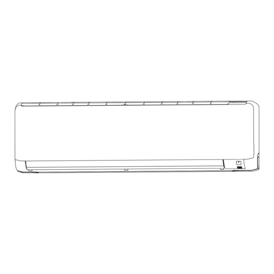
Page 6: Name Of Each Part And Its Function
Name of each part and its function INDOOR UNIT Air inlet panel Unit indication section and remote control signal receiver Wireless remote control Air filter Removes dust or dirt from the inlet air. Page 19 Air-cleaning filter Room temperature detector Unit operation switch Air outlet Air blows out of here. - Page 7 Unit indication section RUN light (green) • Illuminates during operation. • Blinks at the ‘CLEAN operation’. Unit ON/OFF button 3 sec. In emergencies, this button can be used for turning on/off the unit CLEAN operation when remote control is not available. Page 7 1 sec.
- Page 8 How to open the air inlet panel How to close the air inlet panel Push both sides evenly and press further lightly at the center. Place fingers at the recesses on both sides of the panel and pull up the panel to this side so that it will be opened by about 60 degrees.
-
Page 9: Operation And Indication Section For Remote Control
Operation and indication section for remote control Operation section FAN SPEED button OPERATION MODE select button Each time the button is pushed, the Each time the button pushed, the indicator is switched over in turn. indicator is switched over in turn. ON/OFF (luminous) button HI POWER/ECONO button Press for starting operation, press again... -
Page 10: Auto Mode Operation Procedure
AUTO mode operation procedure ■ Automatically selects the operation mode (COOL, DRY) depending on the room temperature when switched on. When the unit is not in AUTO mode: Press MODE button. Move the [ mark] to the (Auto) position. Aim the remote control at the air-conditioner. Press the ON/OFF button. -
Page 11: Cool/Dry/Fan Mode Operation Procedure
COOL/DRY/FAN mode operation procedure Aim the remote control at the air-conditioner. Press the MODE select button. Move the [ mark] to the desirable operation position. (Cool), (Fan), (Dry) Press the ON/OFF button. Press the TEMP button. Press button for the desired temperature. Standard 26°C~28°C 21°C~24°C... -
Page 12: Air Fl Ow Direction Adjustment Procedure
Air fl ow direction adjustment procedure Adjusting air fl ow direction ■ Up/down direction can be adjusted with the AIRFLOW (UP/DOWN) button on the remote control. Each time when you press this button the mode changes as follows: Change to AIRFLOW (UP/DOWN) mode. (Flap stopped) (Swing) ■... -
Page 13: Sleep Operation Procedure
SLEEP operation procedure ■ The unit stops automatically at the end of the set period of time. The room temperature is automatically controlled when the set time lapses, so that the room does not become too cold during cooling. Page 14 Press the SLEEP button. -
Page 14: On-Timer Operation Procedure
ON-TIMER operation procedure ■ Operation starts 5 to 60 minutes before the time that is set so that the room temperature reaches the optimum temperature at that time. Page 14 ON-TIMER operation can be set regardless of whether the air-conditioner is running or not. Example: In the case you wish to bring the temperature to nearly set temperature in at 8:00. -
Page 15: Program Timer Operation Procedure
PROGRAM TIMER operation procedure ■ The timer operations that consist of the combination of the timer being set at both on and off. Once this has been set and operations started, operations will commence and end at the same time every day as long as the ON/OFF button is not pressed. Example: When it is desired to stop at 22:30, and then start operation at 8:00, near the set temperature. -
Page 16: High Power/Economy Operation Procedure
HIGH POWER/ECONOMY operation procedure If the air-conditioner is not operating, aim the remote control at the air-conditioner. Press the ON/OFF button. Press the HI POWER/ECONO button. • When the operating mode is AUTO or COOL Each time the HI POWER/ECONO button is pressed, the indicator is switched in the order of: (HIGH POWER) (ECONOMY) -
Page 17: Concerning Clean Operation
Concerning CLEAN operation ■ CLEAN operation should be run after AUTO, COOL and DRY operation to remove the moisture from inside the indoor unit and control the growth of mold and bacteria. Press the CLEAN switch with the tip of a ballpoint pen. Each time the CLEAN switch is pressed, the indicator is switched in the order of: No indication... -
Page 18: Installation Location Setting
Installation location setting Take the air conditioning unit’s location into account and adjust the left/right airflow range to maximize air-conditioning. If the air conditioning unit is running, press the ON/OFF button to stop. The installation location setting cannot be made while the unit is running. Press the AIR FLOW (UP/DOWN) button and the AIRFLOW... -
Page 19: Remote Control Handling Procedure
Remote control handling procedure Replacing the batteries Using the remote control holder The following cases signify exhausted batteries. Replace old batteries with new ones. • Receiving beep is not emitted when a signal is transmitted. The remote control can be attached to a •... -
Page 20: Operating Hints
Operating hints ■ Please observe the following for the most economic and comfortable use of your unit. Set a suitable room temperature. Clean the fi lters frequently. Avoid direct sunlight and draught. suitable temperature Excessively low temperatures are not good Clogged fi... - Page 21 Cooling is affected by an air fi lter clogged up with dust etc., and the operation noise becomes louder. It may also use NOTE extra electricity. Please clean the air fi lter at appropriate intervals. At the end of the season At the beginning of the season Perform the fan operation for a half day.
-
Page 22: Has The Unit Been Installed Correctly
Has the unit been installed correctly? Suitable installation position • Is there any obstruction in front of the indoor unit, preventing proper ventilation and functioning? • Don’t install the unit in any of the following places: • Where there is a danger of leaking infl ammable gases. •... -
Page 23: Please Remember
Please remember! You cannot restart the unit immediately after you have Restarting has been blocked for 3 minutes after you have stopped or stopped it. after switching off the power during operation, to protect the unit. (RUN light is on) Please wait for three minutes. -
Page 24: When To Contact Your Distributor Without Delay
When to contact your distributor without delay ■ Turn off the power switch immediately and inform your dealer in any of the following situations: The fuse or switch blows continu- The cable becomes extremely hot. ously. The covering of the cable is cracked. CAUTION Fuse often blows. - Page 25 – 24 – RMA012A105G_J-L_RevC_EN.indb 24 RMA012A105G_J-L_RevC_EN.indb 24 12/6/2018 11:48:24 AM 12/6/2018 11:48:24 AM...
- Page 26 INSTALLATION MANUAL Contents Safety precautions ........................26 Selection of installation location ....................28 Installation of indoor unit ......................29 Installation of outdoor unit ......................32 Connection of refrigerant pipings ....................33 How to relocate or dispose of the unit ..................34 Installation of remote control switch ..................35 Earthing work ..........................35 Trial run and operation ........................35 Installations test check points .....................35...
-
Page 27: Safety Precautions
When install the unit, be sure to check whether the selection of installation place, power source WALL TYPE AIR CONDITIONER specifications, usage limitation (piping length, height differences between indoor and outdoor R410A REFRIGERANT USED units, power source voltage and etc.) and installation spaces. Safety precautions •... - Page 28 ❚ Safety precautions CAUTION • Carry out the electrical work for ground lead with care. Do not connect the ground lead to the gas line, water line, lightning conductor or telephone line’s ground lead. Incorrect grounding can cause unit faults such as electric shocks due to short-circuiting. •...
-
Page 29: Selection Of Installation Location
Standard accessories Necessary tools for the installation work (Installation kit) Q'ty Accessories for indoor unit Plus headed driver (Phillips screwdriver) Installation board Knife (Attached to the rear of the indoor unit) Wireless remote control Tape measure Remote contorol holder Hammer Tapping screws Spanner wrench (for installation board 4dia. -
Page 30: Installation Of Indoor Unit
Limitations for one way piping length and vertical height difference Total one way piping length ( ) Max. 25 m Vertical height difference (h) Max. 15 m Installation of indoor unit Installation of installation board Look for the inside wall structures (Intersediate support or pillar INSTALLATOIN SPACE (INDOOR UNIT) (FRONT VIEW) and firaly install the unit after level surface has been checked.) Indoor unit... - Page 31 Preparation of indoor unit The screw of the lid is tightened securely 1 Mounting of connecting wires a Open the air inlet panel. b Remove the lid. c Remove the wiring clamp. d Connect the connecting wire securely to the terminal block. Use cable for interconnection wiring to avoid loosening of the wires.
- Page 32 [Drain hose changing procedures] 1. Remove the drain hose. 2. Remove the drain cap. 3. Insert the drain cap. 4. Connect the drain hose. • Remove the screw and • Remove it with hand • Insert the drain cap which was removed at •...
-
Page 33: Installation Of Outdoor Unit
Removal and installation of the front panel 1 Removing Air inlet panel • Remove the air inlet panel. Latch Air filter • Remove the 8 screws fi xing to the front panel. • Remove the 5 latches in the upper section of the front panel and then remove the front panel from the unit. -
Page 34: Connection Of Refrigerant Pipings
Connection of refrigerant pipings Refrigerant pipe wall thickness and material Pipe diameter [mm] ø6.35 ø12.7 ø15.88 • Select refrigerant pipes of the table shown on the right wall thickness Minimum pipe wall thickness [mm] and material as specified for each pipe size. Pipe material* O-type pipe O-type pipe... -
Page 35: How To Relocate Or Dispose Of The Unit
Air purge 1 Tighten all flare nuts in the pipings both indoor and Compound pressure gauge outside wall so as not to cause leak. Pressure gauge Operation valve cap 2 Connect operation valve, charge hose, manifold valve Gauge manifold Operation valve and vacuum pump as is illustrated right. -
Page 36: Installation Of Remote Control Switch
Installation of remote control switch Mounting method of battery Fixing to pillar or wall • • Uncover the remote control switch, and mount the batter- Conventionally, operate the wireless remote control by ies [R03(AAA, Micro)×2 pieces] in the body regularly. holding in your hand. - Page 37 – 36 – RMA012A105G_J-L_RevC_EN.indb 36 RMA012A105G_J-L_RevC_EN.indb 36 12/6/2018 11:48:26 AM 12/6/2018 11:48:26 AM...