TRENDnet TFC-1000 Quick Installation Manual
Trendnet tfc-1000 media converter: installation guide
Hide thumbs
Also See for TFC-1000:
- Quick installation manual (19 pages) ,
- Specifications (2 pages) ,
- Quick installation manual (12 pages)
Table of Contents
Advertisement
Quick Links
Advertisement
Table of Contents

Related Manuals for TRENDnet TFC-1000


Summary of Contents for TRENDnet TFC-1000
- Page 1 Quick Installation Guide TFC-1000 TFC-210 Series TFC-2000 Series...
-
Page 2: Table Of Contents
Table of Contents Table of Contents English ... 1. Before You Start 2. Product Details ... Hardware Installation LLCF Function ... Technical Specifications ... Troubleshooting ... Version 02.13.2007... -
Page 3: English
1. Before You Start TFC-1000 Fiber Converter Chassis for TFC-210 and TFC-2000 Series Converters: TFC-210 or TFC-2000 Series Fiber Converter: Package Contents TFC-1000 Quick Installation Guide AC Power Cord Mounting Bracket and Screws Package Contents Fiber Converter Quick Installation Guide... -
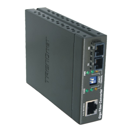
Page 4: Product Details
2. Product Detail 10/100Base-TX to 100Base-FX Fiber Converters Multi/ Model Name Single-Mode TFC-210MST Multi-Mode TFC-210MSC Single-Mode TFC-210S30 TFC-210S20D3 Single-Mode Single/ Bidirectional TFC-210S20D5 1000Base-T to 1000Base-SX/LX Fiber Converters Multi/ Model Name Single-Mode TFC-2000MSC Multi-Mode TFC-2000S20 Single-Mode TFC-2000S50 TFC-2000S10D3 Single-Mode Single/ Bidirectional TFC-2000S10D5 Fiber Power Budget... -
Page 5: Hardware Installation
3. Hardware Installation Installing Two Stand Alone Fiber Converters 1. Connect the fiber cable to the Fiber Converters. 2. Connect an RJ-45 Ethernet cable from the Ethernet port on the fiber converters to an Ethernet port on your switch (e.g TE100-S24R or TEG-S240TX). - Page 6 Installing a Fiber Converter to a Switch 1. Connect the fiber cable from the Fiber Converter to a Fiber Switch (e.g. TE100-S810Fi) 2. Connect an RJ-45 Ethernet cable from the Ethernet port on the Fiber Converters to an Ethernet port on your Switch (e.g.
- Page 7 Installing a Fiber Converter to a PC 1. Connect the fiber cable from the Fiber Converter to a PC with a Fiber Adapter (e.g. TE100-PCIFX+) 2. Connect an RJ-45 Ethernet cable from the Ethernet port on the Fiber Converters to an Ethernet port on your Switch (e.g.
- Page 8 Installing Fiber Converter in a Chassis 1. Using a screwdriver unscrew the Module Bay Cover from the desired bay on the Chassis and remove the cover. Save the screw and cover in case you need to cover up the module bay in the future.
- Page 9 Rack Mount The Chassis can be mounted in an EIA standard-size, 19-inch rack, which can be placed in a wiring closet with other equipment. 1. Attach the mounting brackets to the Chassis's front panel (one on each side), and secure them with the provided screws.
-
Page 10: Connecting The Power
Connecting the Power 1. Connect the supplied power cord to the back of the Chassis. 2. Connect the power cord into a power outlet. 3. Flip the switch to the ON position to power up the Chassis. DIP Switches Switch 1: ON: TX Full Duplex Mode TFC-210 Switch 2: ON: FX Half Duplex series... -
Page 11: Llcf Function
Below are examples on how to read the LLCF Function Table: Example 1: If LLCF is enabled on Fiber Converter 1 and disable on Media Converter 2, when Cable 1 link is down, Fiber Converter 1's Copper and Fiber LED and Fiber Converter 2's Fiber LED will shut off. - Page 12 Cable 4 Link Down Cable 1 Link Down Media Converter 1 Cable 2 Link Down LLCF Disable Media Cable 3 Link Down Converter 2 LLCF Disable Cable 4 Link Down Media Converter 2 Media Converter 1 Copper Fiber Copper Fiber...
-
Page 13: Technical Specifications
Specifications TFC-210 series: IEEE 802.3 10Base-T IEEE 802.3u 100Base-TX & 100Base-FX Standards: TFC-2000 series: 1000Base-T, 1000Base-SX/LX, IEEE 802.3ab/ 802.3z TFC-210 series: Power; 100Mbps, Full Duplex/ Collision, Link/Activity LED Indicators: TFC-2000 series: Power; 1000Mbps, Full Duplex/ Collision, Link/Activity TFC-210 series: 10Base-T – UTP/STP Cat. 3, 4, 5 100Base-TX –... - Page 14 Capacity: Material: Power: Power Consumption: Cooling: Dimensions: Weight: Temperature: Humidity: Certification: Fiber Chassis Ten bays for housing up to Ten media converters Metal AC 100~240V AC, 50/60Hz 90 Watts (Max) One Fan 440 mm × 266mm × 133 mm (W × D × H) Standard 19”...
-
Page 15: Troubleshooting
Third, make sure the power switch is flipped to the ON position. If you still encounter problems or have any questions please contact TRENDnet's Technical Support Department. - Page 16 - 5-Year Warranty If a product does not operate as warranted above during the applicable warranty period, TRENDnet shall, at its option and expense, repair the defective product or deliver to customer an equivalent product to replace the defective item. All products that are replaced will become the property of TRENDnet.
- Page 17 LIABILITY IN CONNECTION WITH THE SALE, INSTALLATION, MAINTENANCE OR USE OF TRENDNET’S PRODUCTS. TRENDNET SHALL NOT BE LIABLE UNDER THIS WARRANTY IF ITS TESTING AND EXAMINATION DISCLOSE THAT THE ALLEGED DEFECT IN THE PRODUCT DOES NOT EXIST OR WAS CAUSED BY CUSTOMER’S OR ANY THIRD PERSON’S MISUSE, NEGLECT, IMPROPER INSTALLATION OR...
- Page 18 Certifications This equipment has been tested and found to comply with FCC and CE Rules. Operation is subject to the following two conditions: (1) This device may not cause harmful interference. (2) This device must accept any interference received. Including interference that may cause undesired operation.
- Page 19 English/Espanol - 24/7 Francais/Deutsch - 11am-8pm, Monday - Friday MET Product Warranty Registration Please take a moment to register your product online. Go to TRENDnet’s website at http://www.trendnet.com 20675 Manhattan Place Torrance, CA 90501 Copyright ©2007. All Rights Reserved. TRENDnet.