Table of Contents
Advertisement
Advertisement
Table of Contents

Related Manuals for Asus ET2700INKS


Summary of Contents for Asus ET2700INKS
-
Page 1: User Manual
User Manual ET2700 Series... - Page 2 ASUSTeK COMPUTER, INC. (“ASUS”). Products and corporate names mentioned in this manual may or may not be registered trademarks or copyrights of their respective companies, and are used for identification purposes only.
-
Page 3: Table Of Contents
Wireless Operation Channel for Different Domains ... 7 France Restricted Wireless Frequency Bands ... 8 REACH ... 9 Global Environmental Regulation Compliance and Declaration ...10 ASUS Recycling/Takeback Services ...10 UL Safety Precaution ...10 ENERGY STAR complied product ...11 DTS Certified Audio System ...11 ET2700 Series CPU Configurations ...11... - Page 4 Using the keyboard ...23 Using the On Screen Display (OSD) Menu ...24 OSD function instruction ...24 Input signal selection ...25 Positioning your All-in-one PC ... 26 Placing on the desktop ...26 Mounting to the wall ...27 Setting up your All-in-one PC ... 30 Connecting the wired keyboard and mouse ...30 Connecting the wireless keyboard and mouse ...30 Powering on the system...31...
-
Page 5: Notices
Notices Federal Communications Commission Statement This device complies with Part 15 of the FCC Rules. Operation is subject to the following two conditions: • This device may not cause harmful interference, and • This device must accept any interference received including interference that may cause undesired operation. -
Page 6: Canadian Department Of Communications Statement
Canadian Department of Communications Statement This digital apparatus does not exceed the Class B limits for radio noise emissions from digital apparatus set out in the Radio Interference Regulations of the Canadian Department of Communications. This class B digital apparatus complies with Canadian ICES-003. IC Radiation Exposure Statement for Canada This equipment complies with IC radiation exposure limits set forth for an uncontrolled environment. -
Page 7: Ce Mark Warning
CE Mark Warning This is a Class B product, in a domestic environment, this product may cause radio interference, in which case the user may be required to take adequate measures. CE marking for devices without wireless LAN/Bluetooth The shipped version of this device complies with the requirements of the EEC directives 2004/108/EC “Electromagnetic compatibility”... -
Page 8: France Restricted Wireless Frequency Bands
France Restricted Wireless Frequency Bands Some areas of France have a restricted frequency band. The worst case maximum authorized power indoors are: • 10mW for the entire 2.4 GHz band (2400 MHz–2483.5 MHz) • 100mW for frequencies between 2446.5 MHz and 2483.5 MHz Channels 10 through 13 inclusive operate in the band 2446.6 MHz to 2483.5 MHz. -
Page 9: Reach
REACH Complying with the REACH (Registration, Evaluation, Authorization, and Restriction of Chemicals) regulatory framework, we publish the chemical substances in our products at ASUS REACH website at http://csr.asus.com/english/REACH.htm. NO DISASSEMBLY No Exposure to Liquids waterproof or oil-proof. -
Page 10: Global Environmental Regulation Compliance And Declaration
ASUS follows the green design concept to design and manufacture our products, and makes sure that each stage of the product life cycle of ASUS product is in line with global environmental regulations. In addition, ASUS disclose the relevant information based on regulation requirements. -
Page 11: Energy Star Complied Product
U.S. Department of Energy helping us all save money and protect the environment through energy efficient products and practices. All ASUS products with the ENERGY STAR logo comply with the ENERGY STAR standard, and the power management feature is enabled by default. The monitor and computer are automatically set to sleep after 15 and 30 minutes of user inactivity. -
Page 12: Safety Information
Safety information Your All-in-one PC ET2700 Series is designed and tested to meet the latest standards of safety for information technology equipment. However, to ensure your safety, it is important that you read the following safety instructions. Setting up your system •... -
Page 13: Sound Pressure Warning
NOTE: Additional information for special situations. All illustrations and screenshots in this manual are for reference only. Actual product specifications and software screen images may vary with territories. Visit the ASUS website at www.asus.com for the latest information. All-in-one PC ET2700 Series... -
Page 14: Welcome
Congratulations on your purchase of All-in-one PC ET2700 Series. The following illustrations display the package contents of your new product. If any of the following items is damaged or missing, contact your retailer. Package contents All-in-one PC ET2700 Series AC adapter Remote Control (optional) All-in-one PC ET2700 Series Welcome... -
Page 15: Getting To Know Your All-In-One Pc
Getting to know your All-in-one PC Front view Refer to the following diagram to identify the components on this side of the system. All-in-one PC ET2700 Series... - Page 16 Webcam LED Indicates that the built-in webcam is enabled. Webcam The built-in webcam with the built-in digital microphone allows you to start video chats online. Digital Microphone (Built-in) The built-in digital microphone can be used for video conferencing, voice narrations, audio recordings, and multimedia applications.
-
Page 17: Rear View
Rear view Refer to the following diagram to identify the components on this side of the system. Kensington® Lock port The Kensington® lock port allows the computer to be secured using Kensington® compatible security products. These security products usually include a metal cable and lock that prevent the computer to be removed from a fixed object. - Page 18 Cable Holder Gather all the cables with this cable holder. Power input The supplied power adapter converts AC power to DC power for use with this jack. Power supplied through this jack supplies power to the PC. To prevent damage to the PC, always use the supplied power adapter.
-
Page 19: Side Views
(low frequency) sounds in your multimedia applications. The subwoofer jack can ONLY be connected to All-in-one PC subwoofers or sound devices by ASUS. DO NOT connect other devices to this jack. Doing so may damage the device. All-in-one PC ET2700 Series... - Page 20 Optical Drive The built-in optical drive may support compact discs (CD), digital video discs (DVD), and/or Blu-ray discs (BD) and may have recordable (R) or re-writable (RW) capabilities. See the marketing specifications for details on each model. Optical Drive Electronic Eject The optical drive eject has an electronic eject button for opening the tray.
-
Page 21: Using The Touch Screen
Using the touch screen All-in-one PC brings digital life to your fingertips. With a few touches, you can make All-in-one PC work at your command. Your touch functions like a mouse device: • Touch = left-click on the mouse • Touch and hold = right-click on the mouse The touch-enabled screen is available on selected models. -
Page 22: Cleaning The Touch Screen
Click Change touch input settings. Click the Touch tab on the top and click the box before Show the touch pointer when I’m interacting with items on the screen. Click OK to finish the configuration. Cleaning the touch screen The touch screen requires periodic cleaning to achieve the best touch sensitivity. Keep the screen clean from foreign objects or excessive dust accumulation. -
Page 23: Using The Keyboard
Using the keyboard Your All-in-one PC comes with a wired or wireless keyboard that facilitates your control of the system. The following keyboard illustration is for reference only. Actual product specifications may vary with territories. Caps Lock Shift Ctrl Caps Lock Shift Ctrl Mute... -
Page 24: Using The On Screen Display (Osd) Menu
Using the On Screen Display (OSD) Menu The On Screen Display (OSD) menu appears if you: • press the MENU button in the front panel; or • connect the HDMI or VGA cable to the rear HDMI-input or Display-input port. OSD function instruction To display the OSD menu, press the MENU button on the front panel. -
Page 25: Input Signal Selection
System Setup • OSD Setup: • Adjusts the horizontal position (H-Position) / vertical position (V-Position) of the OSD menu. • Adjusts the OSD timeout from 10 to 120 seconds. • Enables or disables the DDC/CI (Display Data Channel/Command Interface) function. •... -
Page 26: Positioning Your All-In-One Pc
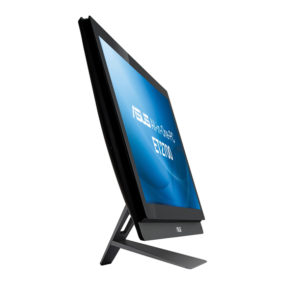
Positioning your All-in-one PC Placing on the desktop Place your All-in-one PC on a flat surface such as a table or desk by setting the stand on setting the stand on the platform. Tilt the display panel to an angle between 5 degrees forward to 20 degrees backwards from an upright position for visual comfort. -
Page 27: Mounting To The Wall
Mounting to the wall To mount your All-in-one PC to the wall, purchase an optional wall mount adapter and a wall mount kit (VESA200 with pad and bracket). Install the wall mount components according to the following instructions. To release the stand, place the All-in-one PC face-down first, resting the display panel on a flat even surface. - Page 28 Align the wall mount adapter to the holes at the back of the All-in-one PC and secure it with the four screws you removed in step 3 Secure the wall mount pad to the adapter with the eight screws (M3 x 8L) that came with the kit, noting the correct orientation.
- Page 29 By following the instructions in the installation manual that came with your wall mount kit (VESA200), fasten the wall mount bracket to the wall using the four screws (M4 x 10L) provided in the kit. Upright your All-in-one PC and hook it on to the wall by sliding the grooves of the wall mount pad into the bracket .
-
Page 30: Setting Up Your All-In-One Pc
Setting up your All-in-one PC Connecting the wired keyboard and mouse Connect the keyboard and the mouse connect the keyboard and mouse to the USB port on the left side of the panel if the keyboard cable is not long enough. . Connecting the wireless keyboard and mouse Install batteries to the wireless keyboard and mouse. -
Page 31: Powering On The System
Powering on the system Connect the supplied AC adapter to the DC IN jack on the rear panel ( voltage 100Vac–240Vac) and then press the Power switch on the right ( system. Powering off • To put the system into suspend mode, press the Power switch system back to the OS, press the Power switch again, click the mouse, touch the display or press any key on the keyboard. -
Page 32: Using The Device Share Function
Using the Device Share function Your All-in-one PC can be used as a standard desktop LCD monitor, and there are more to share. With the Device Share feature enabled, you can share the display panel, rear USB ports, webcam, and the touch screen of the All-in-one PC to any other Microsoft Windows® 7-based laptop / desktop PC. - Page 33 If your laptop / desktop PC has no HDMI support, prepare a male-to-male VGA cable and a male-to-male stereo audio cable. Connect one end of the VGA cable and audio cable to your laptop / desktop PC, and connect the other end of the VGA cable to the Display- input port on the rear side of the All-in-one PC, and the other end of the audio cable to the microphone jack on the side of the All-in-one PC.
-
Page 34: Configuring A Wireless Connection
Configuring a wireless connection Click the wireless network icon with an orange star Select the wireless access point you want to connect to from the list and click Connect to build the connection. If you cannot find the desired access point, click the Refresh icon right corner to refresh and search in the list again. -
Page 35: Configuring A Wired Connection
Configuring a wired connection Using a static IP Click the network icon with a yellow warning triangle in the Windows® Notification area and select Open Network and Sharing Center. Ensure that you have connected the LAN cable to the All-in-one PC. Click Change adapter settings in the left panel. - Page 36 Click Internet Protocol Version 4(TCP/ IPv4) and click Properties. Select Use the following IP address. Enter your IP address, Subnet mask, and Default gateway. If needed, enter the Preferred DNS server address. After entering all the related values, click OK to finish the configuration. All-in-one PC ET2700 Series...
-
Page 37: Using A Dynamic Ip (Pppoe)
Using a dynamic IP (PPPoE) Repeat steps 1–4 in the previous section. Select Obtain an IP address automatically and click OK. (Continue the following steps if using PPPoE) Return to the Network and Sharing Center and then click Set up a new connection or network. - Page 38 Select Broadband (PPPoE) and click Next. Enter User name, Password, and Connection name. Click Connect. Click Close to finish the configuration. All-in-one PC ET2700 Series...
- Page 39 Click the network icon in the notification area and click the connection you just created. Enter your user name and password. Click Connect to connect to the Internet. All-in-one PC ET2700 Series...
-
Page 40: Connecting To External Audio Devices
Connects to ASUS All-in-one PC subwoofer (optional) The subwoofer jack can ONLY be connected to All-in-one PC subwoofers or sound devices by ASUS. DO NOT connect other devices to this jack. Doing so may damage the device. Configuring audio output settings... - Page 41 Select a playback device and click Properties to configure the settings. Do the advanced configurations, such as adjusting the speaker level and output rate. Click OK to finish the configurations. All-in-one PC ET2700 Series...
-
Page 42: Recovering Your System
Recovering your system Using the hidden partition The recovery partition includes an image of the operating system, drivers, and utilities installed on your system at the factory. The recovery partition provides a comprehensive recovery solution that quickly restores your system’s software to its original working state, provided that your hard disk drive is in good working order. -
Page 43: Using The Usb Storage Device (Usb Restore)
Based on the different situations in the previous step, data on the selected USB storage device or on the selected partition will be cleared. Click Backup to start backup. You will lose all your data on the selected USB storage device or on the selected partition. Ensure to back up your important data beforehand. - Page 44 Manufacturer Address, City Country Authorized Representative in Europe ASUS COMPUTER GmbH Address, City Country All-in-one PC ET2700 Series ASUSTek COMPUTER INC. No. 150, LI-TE RD., PEITOU, TAIPEI 112, TAIWAN R.O.C TAIWAN HARKORT STR. 21-23, 40880 RATINGEN GERMANY...