
Related Manuals for Daikin ROTEX RHYHBH05AA


Summary of Contents for Daikin ROTEX RHYHBH05AA
- Page 1 Installation manual ROTEX HPU hybrid heat pump module RHYHBH05AA Installation manual RHYHBH08AA English ROTEX HPU hybrid heat pump module RHYHBX08AA...
- Page 2 3P353176-2A...
-
Page 3: Table Of Contents
Table of contents Table of contents About the documentation 1 About the documentation About this document About this document..............Target audience 2 About the box Authorised installers Indoor unit.................. 2.1.1 To unpack the indoor unit ........... Documentation set 2.1.2 To remove the accessories from the indoor unit..This document is part of a documentation set. -
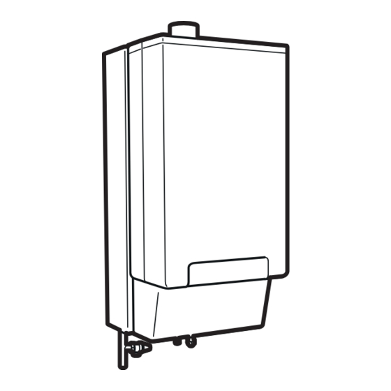
Page 4: To Remove The Accessories From The Indoor Unit
3 Preparation 2.1.2 To remove the accessories from the indoor unit The installation manual, operation manual, addendum book for optional equipment, general safety precautions, quick installation guide, and boiler communication cable are located in the upper part of the box. The connection pieces for the gas boiler are attached to the water piping. -
Page 5: Installation
4 Installation Item Description Wires Maximum running current Outdoor ambient temperature sensor Indoor ambient temperature sensor Heat pump convector 100 mA Field supplied components Shut-off valve 100 mA Electricity meter Domestic hot water pump Alarm output Changeover to external heat source control Space cool/heat operation control Power consumption... -
Page 6: Mounting The Indoor Unit
4 Installation Mounting the indoor unit 4.2.1 To install the indoor unit 1 Put the installation pattern (see box) on the wall and follow the steps as shown below. 2 Fix the wall bracket to the wall with 2 M8 bolts. Connecting the refrigerant piping See the outdoor unit installation manual for all guidelines, specifications and installation instructions. -
Page 7: Connecting The Water Piping
4 Installation 4.4.3 To insulate the water piping Connecting the water piping The piping in the complete water circuit must be insulated to prevent condensation during cooling operation and reduction of the heating 4.4.1 Connecting the water piping of the indoor and cooling capacity. -
Page 8: To Connect The Main Power Supply Of The Indoor Unit
4 Installation Routing Possible cables (depending on unit type and installed options) ▪ Interconnection cable between indoor unit and gas boiler (see boiler manual for connection instructions) ▪ Outdoor ambient temperature sensor (option) ▪ User interface ▪ Indoor ambient temperature sensor (option) ▪... -
Page 9: To Connect The User Interface
4 Installation 4.5.3 To connect the user interface 4.5.5 To connect the electrical meter 1 Connect the user interface cable to the indoor unit. INFORMATION In case of an electrical meter with transistor output, check the polarity. The positive polarity MUST be connected to X5M/7;... -
Page 10: To Connect The Gas Meter
4 Installation 4.5.6 To connect the gas meter 4.5.8 To connect the alarm output 1 Connect the alarm output cable to the appropriate terminals as INFORMATION shown in the illustration below. In case of a gas meter with transistor output, check the polarity. -
Page 11: To Connect The Power Consumption Digital Inputs
5 Configuration 4.5.10 To connect the power consumption digital NOTICE inputs The explanation about the configuration in this chapter gives you ONLY basic explanations. For more detailed 1 Connect the power consumption digital inputs cable to the explanation and background information, see the installer appropriate terminals as shown in the illustration below. - Page 12 5 Configuration 5 Select the required action: To access the most used commands ▪ Send data: the user interface you are operating contains the To access the installer settings correct data and the data on the other user interface will be overwritten.
-
Page 13: Basic Configuration
5 Configuration Code Description [A.2.1.9] [F-0D] Pump operation: ▪ 0 (Continuous): Continuous pump operation, regardless of thermo ON or OFF condition. ▪ 1 (Sample): When thermo condition occurs, the pump runs every 3 Set the system layout settings: Standard, Options, Capacities. 5 minutes and the water temperature For more details, see "5.1.2 Basic configuration"... - Page 14 5 Configuration Thermostats and external sensors Demand PCB Code Description Code Description [A.2.2.4] [C-05] External room thermostat for the main [A.2.2.7] [D-04] Demand PCB zone: Indicates if the optional demand PCB is ▪ 1 (Thermo ON/OFF): When the used installed. external room thermostat...
- Page 15 5 Configuration Code Description Code Description [A.3.1.1.3] [1-00] Weather-dependent curve (heating): [A.3.1.2.4] [0-04] Only for RHYHBX08. Weather- dependent curve (cooling): [1-01] [0-05] [1-02] [0-06] [1-02] [1-03] [0-07] [0-05] [1-03] [0-04] [1-00] [1-01] [0-07] [0-06] ▪ T : Target leaving water temperature (main) ▪...
- Page 16 5 Configuration Quick heat up function Code Description [C-0A] Indoor quick heat up function: ▪ 0: OFF. ▪ 1 (default): On. Only applicable in case of room thermostat control. The function will start up the gas boiler when the actual room temperature is 3°C lower than the desired room temperature.
-
Page 17: Menu Structure: Overview Installer Settings
5 Configuration 5.1.3 Menu structure: Overview installer settings System layout Options Compressor type Unit control method DHW tank type Solar kit Room thermostat Additional Temperature range Room temp. offset Space cooling On temp Temperature range Scheduled DHW Disinfection SP mode Conversion persons Operation day Equilibrium temp. - Page 18 5 Configuration UFH screed dryout Solar pump Installation manual RHYHBH05AAV3 + RHYHBH/X08AAV3 ROTEX HPU hybrid heat pump module 4P353065-1 – 2013.05...
-
Page 19: Commissioning
6 Commissioning To perform a test run Commissioning 1 Go to [A.7.1]: > Installer settings > Commissioning > Test run. 2 Select a test and press . Example: Heating. Checklist before test run 3 Select OK and press Do NOT operate the system before the following checks are OK: Result: The test run starts. -
Page 20: Hand-Over To The User
7 Hand-over to the user Hand-over to the user Once the test run is finished and the unit operates properly, please make sure the following is clear for the user: ▪ Fill in the installer setting table (in the operation manual) with the actual settings. -
Page 21: Technical Data
8 Technical data Technical data Wiring diagram 8.1.1 Wiring diagram – components: Indoor unit See the internal wiring diagram supplied with the unit (on the inside of the indoor unit switch box cover). The abbreviations used are listed below. 4D082241-1 page 1 RHYHBH05AAV3 + RHYHBH/X08AAV3 Installation manual ROTEX HPU hybrid heat pump module... - Page 22 8 Technical data 4D082241-1 page 2 Installation manual RHYHBH05AAV3 + RHYHBH/X08AAV3 ROTEX HPU hybrid heat pump module 4P353065-1 – 2013.05...
- Page 23 8 Technical data Main PCB (hydrobox) Notes to go through before starting the unit User interface PCB English Translation Solar pump station PCB Indoor/outdoor communication On/OFF thermostat Field wiring terminal for AC Heat pump convector Field wiring terminal for DC Digital I/O PCB Earth wiring Receiver PCB (Wireless On/OFF...
- Page 24 4P353065-1 2013.05...