
Related Manuals for True PERFORMANCE 1000


Summary of Contents for True PERFORMANCE 1000
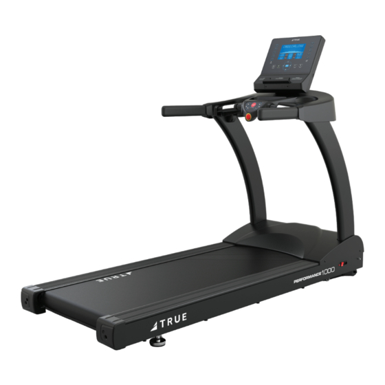
- Page 1 PERFORMANCE 1000/3000/8000 TREADMILL OWNER’S MANUAL MODEL TPS1000/TPS3000/TPS8000 MAN-TPS REV01...
- Page 3 !ماھ .اھمیلست يلعفلا جتنملا فلتخت دق .جذومنلا يھ ةضورعملا تاجتنملا عیمج .راعشإ نود رییغتلل ةلباق جماربلاو تازیملاو ،جتنملا تافصاوم ةرایز ىجری كلاملا لیلد نآلا ىتح لصی ام مظعملhttps://shop.truefi tness.com/customer-service/user-manuals/ ةرایز ىجری ،ةیفاضإ تاغل يف تادنتسمللhttps://shop.truefi tness.com/customer-service/user-manuals/ WICHTIG! Alle hier gezeigten Produkte sind Prototypen. Das tatsächliche Produkt ausgeliefert wird, kann variieren. Produkt- Spezifi...
- Page 4 Monday - Thursday 8:30am - 6:00pm (CST) Friday 8:30am - 5:00pm (CST) Contacting Our Sales Team Interested in owning more TRUE products? Please contact us with any product inquires so that we may direct you to the appropriate sales representative to help answer your questions. Address...
- Page 5 You may receive a shipment that looks intact and discover once the box has been opened that there are hidden damages. Please notify the carrier immediately. TRUE will not be able to fi le a claim if the carrier is not notifi ed in a timely manner.
-
Page 6: Table Of Contents
TABLE OF CONTENTS SAFETY INSTRUCTIONS IMPORTANT SAFETY INSTRUCTIONS—SAVE THESE INSTRUCTIONS................7 POWER REQUIREMENTS..............................9 GROUNDING INSTRUCTIONS..............................9 SPACE REQUIREMENTS..............................10 SPECIFICATIONS..................................10 WARNING DECALS................................11 COMPLIANCES...................................11 USE OF THE SAFETY KEY..............................12 ASSEMBLY INSTRUCTIONS PREASSEMBLY CHECKLIST...............................13 ASSEMBLY STEPS................................17 PRODUCT FEATURES TREADMILL OVERVIEW..............................30 CONSOLE OVERVIEW................................31 CARE AND MAINTENANCE INSPECTION..................................32 CLEANING THE EQUIPMENT.............................32 LEVELING THE TREADMILL.............................32... -
Page 7: Safety Instructions
Equipment should be immediately taken out of product. use if it fails to work properly or when a warning is • Never operate a TRUE product if it has a damaged presented electronically. power cord or electrical plug, or if it has been •... - Page 8 • Allow only one person at a time on the equipment carefully retrieve it. If the item cannot be reached, while it’s operating. contact TRUE product support. • Do not allow animals on or near the equipment while • Any changes or modifi cations to this equipment in operation.
-
Page 9: Power Requirements
POWER REQUIREMENTS Read and understand all instructions before plugging any TRUE power cord into an electrical outlet. DEDICATED LINE This product requires a dedicated line. A dedicated line assures that adequate power is available for safe operation over the life of your TRUE product. -
Page 10: Space Requirements
SPACE REQUIREMENTS TRUE recommends leaving a minimum of 24” (61cm) on each side of the equipment and a 79” (200cm) safety zone at the rear of the equipment. 24” (61cm) 24” 79” (61cm) (200cm) 24” (61cm) SPECIFICATIONS • DIMENSIONS (L X W X H) -
Page 11: Warning Decals
WARNING: Replace warning labels that may be worn, damaged, or missing. To replace any worn or missing decals contact TRUE product support (service@truefi tness.com // 800.883.8783). TRUE FITNESS TECHNOLOGY, INC O O L L O O G G Y Y Y Y... -
Page 12: Use Of The Safety Key
USE OF THE SAFETY KEY The safety key is a tethered device that attaches to the user and the treadmill. Removal of the safety key from the treadmill will stop belt motion to prevent injury if the user is unable to continue. 1. -
Page 13: Assembly Instructions
DO NOT use a box cutter. DO NOT slice into the packaging. VERIFY BOX CONTENTS IMPORTANT! Please verify box contents. If you have questions, or if there are any missing parts, contact product support (service@truefi tness.com // 800.883.8783). TOOLS NEEDED FOR INCLUDED... - Page 14 Box Contents Part Description TPS9100 ASSEMBLY, UPPER, TPS NOTE: Using a #2 Phillips screwdriver, remove and discard the three screws securing the bottom cover to upper tps. These three screws are used for shipping purposes only. All hardware needed to fully assemble this machine is included in the hardware pack. TPS* ASSEMBLY, BASE, TPS* *Base assembly parts for Performance Treadmill models are as follows:...
- Page 15 Box Contents Part Description TPS9160 ASSEMBLY, LEFT PEDESTAL WITH CABLES, TPS, BLACK TPS9109 COVER, REAR CONSOLE, TPS, BLACK RT0136BK COVER, WIRE, BLACK PS0036A POWER CORD, RIGHT ANGLE, PS 300CM XM0137 ASSEMBLY, POLAR CHEST STRAP, T34, XHA-T34 MAN-TPS MANUAL, TPS1000/3000/8000...
- Page 16 Box Contents Part Description TPS9170 HARDWARE PACK, TPS1000/TPS3000/TPS8000 RT0011 RT0137 TI0076 TCS0024 TPS8123 PS0103...
-
Page 17: Assembly Steps
ASSEMBLY STEPS STEP 1—REMOVE MOTOR AND PEDESTAL COVERS Tools Used in this Step Parts Used in this Step #2 Phillips Screwdriver Part Description PS0035 SCREW, M5 X P0.8 X 15 SCA5-15 RT0139BK COVER, LEFT, PEDESTAL COVER, BLACK RT0140BK COVER, RIGHT, PEDESTAL COVER, BLACK RT0020BK COVER, MOTOR, BLACK 1. - Page 18 STEP 2—ATTACH PEDESTAL ASSEMBLIES Tools Used in this Step Parts Used in this Step 5mm Allen Wrench Part Description PS0103 BOLT, M8 X 75MM, K-298A RT0011 LOCK WASHER, INTERNAL TOOTH - SPD8 TPS9150 PEDESTAL, RIGHT, TPS, BLACK 17mm Wrench TPS9160 ASSEMBLY, LEFT PEDESTAL WITH CABLES, TPS, BLACK 1.
- Page 19 STEP 3—ROUTE AND CONNECT LOWER CABLES—INSTALL OPTIONAL AUXILIARY POWER SUPPLY (IF NEEDED*) Tools Used in this Step Parts Used in this Step PART DESCRIPTION 00595500* FUYANG POWER SUPPLY 12V 6AMP 7/16” Wrench TC6085_005* ZIP TIE Wire Cutters* *NOTE: Certain touch screen and PVS consoles require the optional auxiliary power supply. Carefully make the following cable connections between the pedestals and the base: •...
- Page 20 STEP 3—ROUTE AND CONNECT LOWER CABLES—INSTALL OPTIONAL AUXILIARY POWER SUPPLY (IF NEEDED*) CONTINUED IF THE OPTIONAL POWER SUPPLY IS BEING USED, CONNECT THE AUXPS POWER CABLE FROM THE LEFT PEDESTAL TO THE DC CONNECTOR ON THE POWER SUPPLY IF THE OPTIONAL POWER SUPPLY IS BEING USED TUCK THE AUXPS DC CONNECTOR FROM THE LEFT PEDESTAL...
- Page 21 STEP 4—ATTACH THE UPPER ASSEMBLY Tools Used in this Step Parts Used in this Step 5mm Allen Wrench Part Description TPS9100 ASSEMBLY, UPPER, TPS TPS8123 SCREW, M8 X 90MM TPS9104 COVER, RIGHT, UPPER , TPS, BLACK TPS9105 COVER, LEFT, UPPER, TPS, BLACK 1.
- Page 22 STEP 5—ROUTE UPPER CABLES AND SECURE WITH CABLE TIE Route the IO cable and coaxial cable along the upper weldment tube, through the cable tie, and out through the opening to the console rack. IMPORTANT! Leave enough cable length so you can make the cable connections to the console and then tighten cable tie.
- Page 23 STEP 6—TIGHTEN PEDESTALS Tools Used in this Step Hardware Tightened in this Step/Parts Used in this Step 5mm Allen Wrench Part Description PS0103 BOLT, M8 X 75MM, K-298A TCS4035 BOLT, M10xP1.5x25 17mm Wrench 1. Fully tighten the two (2) bolts on the front of the left and right pedestals. 2.
- Page 24 STEP 7—ATTACH CONSOLE, CONNECT POWER CORD, AND CALIBRATE Parts Used in this Step Tools Used in this Step Part Description #2 Phillips Screwdriver PS0036A POWER CORD, RIGHT ANGLE, PS 300CM 1. Using a #2 Phillips screwdriver, secure the console to the console mast using the hardware preassembled to the console (00567800 // SCREW, M5-.8X12 COMBO PHILLIPS/COMMON TRUSS HEAD - ACG BLACK // QTY 4).
- Page 25 STEP 8—ATTACH REAR CONSOLE COVER, MOTOR COVER, AND CAP COVERS Parts Used in this Step Tools Used in this Step Part Description #2 Phillips Screwdriver TI0076 PHCS, M4XP0.7X12 TPS9109 COVER, REAR CONSOLE, TPS, BLACK PS0035 SCREW, M5 X P0.8 X 15 SCA5-15 RT0139BK COVER, LEFT, PEDESTAL COVER, BLACK RT0140BK...
- Page 26 STEP 9—ATTACH THE BOTTOM COVER TO THE UPPER ASSEMBLY Tools Used in this Step Parts Used in this Step #2 Phillips Screwdriver Part Description TPS9106 COVER, UPPER PLASTICS, BOTTOM, TPS, BLACK TCS0024 SCREW, SEMS, M4XP0.7X12, NYLOK, BLACK TPS9106 TCS0024...
- Page 27 STEP 10—ATTACH THE WIRE COVER TO THE UPPER ASSEMBLY Tools Used in this Step Parts Used in this Step #2 Phillips Screwdriver Part Description RT0136BK COVER, WIRE, BLACK RT0137 PHCS, M3X12 - SCI4-12, BK RT0137 RT0136BK...
- Page 28 STEP 11—ATTACH THE SAFETY KEY Tools Used in this Step #2 Phillips Screwdriver 1. Remove the safety key from the hardware kit. 2. Attach safety key magnet to front of the treadmill. 3. Use the screw on the upper assembly bottom cover to tether the safety key to the treadmill. IMPORTANT! •...
- Page 29 STEP 12—LEVEL THE TREADMILL 1. Verify the treadmill is resting on the fl oor and not on any packaging materials. 2. Use the wing nuts on the leveling feet to adjust the feet until the treadmill is level. 3. Once the treadmill is level, fully tighten both wing nuts. NOTE: You should be able to loosen and tighten the wing nuts by hand.
-
Page 30: Product Features Treadmill Overview
PRODUCT FEATURES TREADMILL OVERVIEW Console Assembly Contact Heart Contact Heart Rate Grip Rate Grip Safety Key Straddle Covers Soft System® Belt Power Cord Inlet ON/OFF Switch Circuit Belt Breaker Adjustment Bolts Adjustable Soft Select* Leveling Feet Console Assembly—The console allows the user to set Belt Adjustment Bolts—An adjustment system that up a workout program and control the treadmill during a allows the users to adjust the belt tracking and tension as... -
Page 31: Console Overview
CONSOLE OVERVIEW Console Display Tablet Warning Holder Label Headphone USB Port Jack Contact Heart Contact Heart Rate Grip Rate Grip Quick Touch Quick Touch Incline Keys Speed Keys Safety Key STOP Key Console Display—Used to monitor and/or control STOP Key—Stops/Pauses a workout. Press and hold this workouts and for feature navigation. -
Page 32: Care And Maintenance
It is important to perform the minor maintenance tasks described in this section. Failure to maintain the treadmill as described here could void the TRUE Warranty. To reduce the risk of electrical shock, always unplug the unit from its power source before cleaning or performing any maintenance tasks. -
Page 33: Running Belt Alignment
RUNNING BELT ALIGNMENT Proper belt alignment allows the belt to remain centered and ensures smooth operation. Realigning the belt takes a few simple adjustments. If you are unsure about this procedure, contact TRUE product support: • www.truefi tness.com • 800.883.8783 •... -
Page 34: Tensioning The Running Belt
If the drive belt is loose, it feels similar to the walking belt being loose. Tightening the drive belt should only be done by a trained service person, contact TRUE product support for assistance. -
Page 35: Lubricating The Running Belt
SCHEDULING QUARTERLY PREVENTATIVE MAINTENANCE WITH A SERVICE PROVIDER TRUE recommends scheduling quarterly preventative maintenance with a qualifi ed service provider. Please contact your dealer or visit www.truefi tness.com to contact a local TRUE authorized service provider. Quarterly Preventative Maintenance •... -
Page 36: Troubleshooting
This troubleshooting information is intended to assist in diagnostics only and is not all inclusive. Technical specifi cations, error codes, and programming are subject to change without notice. TRUE accepts no liability for any damage or loss suff ered by persons whom rely wholly or in part on any description or statement contained within this manual. Please visit www.truefi... - Page 37 / fails integrity Reconfi gure console Firmware and software Confi guration check versions are not Reinstall software/fi rmware compatible -- Contact TRUE product support Fault CN01: Internal Console Math error - software Console confi gured Power cycle machine -- Fault incorrectly Reconfi...
- Page 38 High belt tension support C. Low line voltage Check drive belt and D. Dirty or misaligned walking belt tension speed sensor C. Contact TRUE product support D. Contact TRUE product support Fault SP02: Belt Over Speed Tread motor rpm is higher...
-
Page 40: Warranty Information
® parts of the TRUE product (the “Product”) listed below, under normal use and service, shall be free of manufacturing defects in workmanship and materials only for the period of time beginning from the original date of purchase set forth below. - Page 41 This limited warranty applies to but may not be limited to the treadmill elevation motor, upper control board, deck, running belt and drive belt. TRUE shall not warrant the performance of the heart rate system on its products, as the heart rate system performance varies, based on user’s physiology, age, method of use, and other factors.
- Page 42 SAVE TIME AND REGISTER ONLINE! https://shop.truefi tness.com/customer-service/warranty-registration/ THE TRUE LIMITED WARRANTY IS SUBJECT TO AND WILL BE IN ACCORDANCE WITH THE CONDITIONS SET FORTH BELOW: This limited warranty is valid for the United States and 13. This limited warranty does not cover damage or equipment Canada only.
- Page 43 Warranty Registration PLEASE RETAIN THIS PORTION FOR YOUR RECORDS BASE SERIAL NUMBER: Thank you for purchasing a TRUE product! To validate CONSOLE SERIAL NUMBER: your product warranty, please register your product within 30 days of purchaser’s receipt of this product.
- Page 44 T R U E F I T N E S S . C O M I N T E G R I T Y M A T T E R S TRUE Fitness Technology, Inc | 865 Hoff Road, St. Louis, MO 63366 © 2023 TRUE. All Rights Reserved.