Table of Contents
Advertisement
Quick Links
O
PERATOR'S
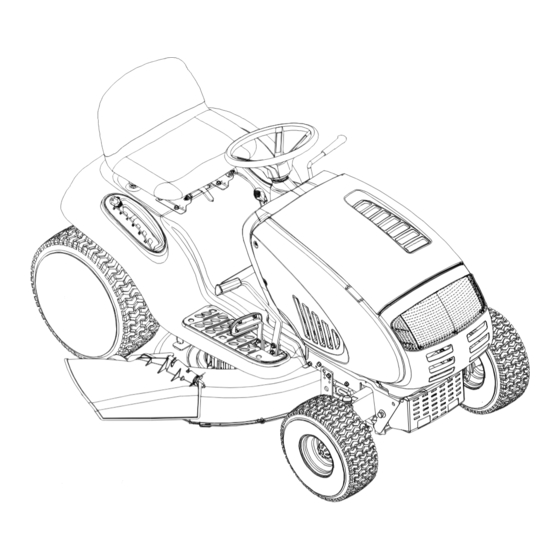
Model 619 Shown
IMPORTANT: READ SAFETY RULES AND INSTRUCTIONS CAREFULLY
Warning:
This unit is equipped with an internal combustion engine and should not be used on or near any unimproved forest-covered,
brush-covered or grass-covered land unless the engine's exhaust system is equipped with a spark arrester meeting applicable local or
state laws (if any). If a spark arrester is used, it should be maintained in effective working order by the operator. In the State of California
the above is required by law (Section 4442 of the California Public Resources Code). Other states may have similar laws. Federal laws
apply on federal lands. A spark arrester for the muffler is available through your nearest engine authorized service dealer or contact the
service department, P.O. Box 361131 Cleveland, Ohio 44136-0019.
MTD LLC, P.O. BOX 361131 CLEVELAND, OHIO 44136-0019
PRINTED IN U.S.A.
M
ANUAL
Hydrostatic Lawn Tractor
Models 617
618
619
FORM NO. 770-10317B.fm
(12/2001)
Advertisement
Table of Contents

Related Manuals for MTD 619


Summary of Contents for MTD 619
- Page 1 A spark arrester for the muffler is available through your nearest engine authorized service dealer or contact the service department, P.O. Box 361131 Cleveland, Ohio 44136-0019. MTD LLC, P.O. BOX 361131 CLEVELAND, OHIO 44136-0019 FORM NO. 770-10317B.fm (12/2001) PRINTED IN U.S.A.
-
Page 2: Table Of Contents
Off-Season Storage ..................23 Attachments & Accessories................23 Troubleshooting ....................24 Models 617, 618 & 619 Parts List ..............26 FINDING MODEL NUMBER This Operator’s Manual is an important part of your new lawn tractor. It will help you assemble, prepare and maintain the unit for best performance. -
Page 3: Important Safe Operation Practices
SECTION 1: IMPORTANT SAFE OPERATION PRACTICES WARNING: This symbol points out important safety instructions which, if not followed, could endanger the personal safety and/or property of yourself and others. Read and follow all instructions in this manual before attempting to operate this machine. Failure to comply with these instructions may result in personal injury. - Page 4 Contact an 3. Do not try to stabilize the machine by putting your authorized MTD service dealer for assistance. foot on the ground. 4. Do not use a grass catcher on steep slopes.
- Page 5 Wash your skin and change clothes immediately. a. Use only an approved gasoline container. by an authorized MTD Service dealer. b. Never fill containers inside a vehicle or on a 4. Check brake operation frequently as it is subjected truck or trailer bed with a plastic liner.
- Page 6 6. Replace the blade(s) with the original equipment 12. Grass catcher components and the discharge manufacturer’s (O.E.M.) blade(s) only, listed in this cover are subject to wear and damage which could manual. “Use of parts which do not meet the expose moving parts or allow objects to be thrown.
-
Page 7: Slope Gauge
SECTION 2: SLOPE GAUGE... -
Page 8: Tractor Set-Up
SECTION 3: TRACTOR SET-UP Attaching the Battery Cables Service the engine with gasoline and oil as instructed in the separate Briggs & Stratton Operator/Owner Manual (or Kohler engine’s Owner’s Manual) packed with your NOTE: The positive battery terminal is marked Pos. tractor. -
Page 9: Know Your Lawn Tractor
SECTION 4: KNOW YOUR LAWN TRACTOR NOTE: Steering Wheel not shown for clarity. † Style varies by model ‡ If so equipped PTO (Power Take-off) Lever‡ Cruise Control Button‡ PTO (Power Take-off) Knob‡ Ignition Switch Choke Control‡ Brake Pedal Parking Brake Button Drive Pedal Cup Holder‡... - Page 10 Throttle Control Lever Ignition Switch The throttle control lever is located on the right side of Never leave running WARNING: the tractor’s dash panel. This lever controls the speed machine unattended. Always disengage PTO, of the engine and, on some models, when pushed all move shift lever into neutral position, set the way forward, the choke control also.
- Page 11 Systems Indicator Monitor Electric PTO (Power Take-off) Knob Your tractor is equipped with either an hour meter or an ammeter as part of two available systems indicator To engage the power to the monitors. Locate the monitor on the left side of your cutting deck or other (separately dash panel and compare it to both shown in Figure 5.
-
Page 12: Operating Your Lawn Tractor
• DO NOT MOW WHEN CHILDREN OR OTHERS ARE AROUND. Contact an authorized MTD service dealer. The safety • NEVER CARRY CHILDREN, EVEN WITH BLADES OFF. • LOOK DOWN AND BEHIND BEFORE AND WHILE BACKING. - Page 13 NOTE: WARNING: The deck wheels are an anti-scalp feature of Do not leave the seat of the the deck and are not designed to support the weight of tractor without first placing the PTO knob (or the cutting deck. lever) in the disengaged (OFF) position, depressing the brake pedal and engaging the Refer to Leveling the Deck on page 15 of this manual for parking...
- Page 14 WARNING: • Locate the hydrostatic bypass rod in the rear of the Do not mow on inclines with a tractor. See Figure 7. slope in excess of 15 degrees (a rise of approximately 2-1/2 feet every 10 feet). The tractor could overturn and cause serious injury.
-
Page 15: Making Adjustments
• Keep the throttle lever in the FAST (rabbit) position • For best results it is recommended that the first two for the most efficient use of the cutting deck or other laps be cut with the discharge thrown towards the (separately available) attachments. - Page 16 • Determine the approximate distance necessary for • Measure the distance from the outside of the left proper adjustment and proceed, if necessary, to the blade tip to the ground and the distance from the next step. outside of the right blade tip to the ground. Both •...
-
Page 17: Maintaining Your Lawn Tractor
Quick-adjust Seat Hex Nut and Pivot Bar To adjust the position of the seat on models equipped Lock Washer with a seat adjustment lever, move the lever to the left and slide the seat forward or rearward. Make sure seat is locked into position before operating the tractor. - Page 18 Spark Plug(s) Check engine oil level before each use as instructed in the Briggs & Stratton Operator/Owner Manual (or The spark plug(s) should be cleaned and the gap reset Kohler engine’s Owner’s Manual) packed with your once a season. Spark plug replacement is unit.
-
Page 19: Service
SECTION 8: SERVICE Tires Blade Separation WARNING: Never exceed the maximum inflation pressure shown on the sidewall of the tire. The recommended operating tire pressure is 10 psi for the rear tires and 14 psi for the front tires. Refer to the Worn Blade Edge tire sidewall for exact tire manufacturer’s recommended or maximum psi. - Page 20 Battery • Place the PTO knob (or lever) in the disengaged (OFF) position and engage the parking brake. The battery is sealed and is maintenance-free. Acid • Lower the deck by moving the deck lift lever into the levels cannot be checked. bottom notch on the right fender.
- Page 21 The V-belts found on your tractor are • Grasp the rearmost portion of the PTO idler bracket IMPORTANT: specially designed to engage and disengage safely. A and pivot it toward the discharge chute to relieve substitute (non-OEM) V-belt can be dangerous by not tension on the PTO belt.
- Page 22 Lower the engine pulley far enough to be If you don’t, see an authorized MTD service dealer to able to remove the upper drive belt from around have the belt changed.
-
Page 23: Off-Season Storage
SECTION 10: ATTACHMENTS & ACCESSORIES The following attachments and accessories are compatible for Lawn Tractor Models 617, 618 & 619. See the retailer from which you purchased your tractor, an authorized MTD Service Dealer or phone (800) 800-7310 for information regarding price and availability. -
Page 24: Troubleshooting
SECTION 11: TROUBLESHOOTING Trouble Possible Cause(s) Corrective Action Engine fails to start PTO knob (or lever) engaged. Disengage PTO. Parking brake not engaged. Engage parking brake. Spark plug wire(s) disconnected. Connect wire(s) to spark plug. Throttle control lever not in correct Place throttle lever to FAST position. -
Page 26: Models 617, 618 & 619 Parts List
SECTION 12: MODELS 617, 618 & 619 PARTS LIST B&S OHV V-Twin B&S Opposed Twin (for throttle) (for starter cable) (for choke) (deflector must face forward) B&S OHV Single Kohler... - Page 27 Exhaust Gasket (B&S OHV Single) 746-1084 Throttle Cable (B&S OHV Single) 732-0966 Extension Spring, .275 x 1.25 (B&S OHV Single) 751B213146 Casing Clamp (B&S OHV Single) NOTE: Engine accessory parts are applicable to all 617, 618 & 619 model tractors except where otherwise noted.
- Page 28 Models 617 & 618...
- Page 29 Models 617 & 618 REF. PART REF. PART DESCRIPTION DESCRIPTION 683-0195 Bracket Assembly (8-style) 731-2247A Hood Plenum 710-0599 Self-tapping Screw, 1/4-20 x .5 (Models with B&S OHV V-Twin) 710-0751 Hex Cap Screw, 1/4-20 x .62 731-2248 Hood Plenum 710-0924 Phillips Pan Screw, 1/4-20 x .75 (Models with B&S Opposed Twin) 710-1017 Truss Phillips Screw, 1/4-20 x .625...
- Page 30 Model 619...
- Page 31 Model 619 REF. PART REF. PART DESCRIPTION DESCRIPTION 783-1346 Grill Support Bracket (9-style) 731-1857 Throttle Control Knob 710-0599 Self-tapping Screw, 1/4-20 x .5 731-2225C Dash Panel (Models w/ Electric PTO) 710-0528 Hex Cap Screw, 5/16-18 x 1.25 731-2122C Dash Panel (Models w/ Manual PTO) 710-0924 Phillips Pan Screw, 1/4-20 x .75...
- Page 32 Models 617, 618 & 619 Models w/ Quick-adjust Seat Models w/ Manually Adjusting Seat...
- Page 33 Models 617, 618 & 619 REF. PART REF. PART DESCRIPTION DESCRIPTION 747-1130B Deck Stabilizer Rod 783-1279 Fender, 4-Style† (Shown) 683-0197B Lift Shaft Assembly 783-0839B Fender, 7-Style‡ 711-0332 Clevis Pin, .5 x .78 783-1489 Seat Mounting Bracket 712-0206 Hex Nut, 1/2-13 710-1268 Screw, #10-16 x .375...
- Page 34 Models 617, 618 & 619...
- Page 35 Models 617, 618 & 619 REF. PART REF. PART DESCRIPTION DESCRIPTION 710-0604A Self-tapping Screw, 16-18 x .625 736-0162 Flat Washer, .64 x 1.0 x .12 783-0726A RH Pivot Support Bracket 736-0187 Flat Washer, .64 x 1.24 x .06† 783-0727 LH Pivot Support Bracket 736-0316 Flat Washer, .78 x 1.589 x .06‡...
- Page 36 Models 617, 618 & 619 Attach Spring Ref. 32...
- Page 37 Models 617, 618 & 619 REF. PART REF. PART DESCRIPTION DESCRIPTION 17840 Transaxle Mounting Bracket 756-0981A Flat Idler Pulley, 2.75 618-0319 Hydrostatic Transmission 756-1166 Input Pulley, 5.0 629-0949A Reverse Wire Harness Adapter & Ground 783-0810 Transmission Torque Bracket 736-0242 Bell Washer, .34 x .872...
- Page 38 Models 617, 618 & 619 (w/ Electric PTO) 46-inch 42-inch Deck Deck...
- Page 39 Models 617, 618 & 619 REF. PART REF. PART DESCRIPTION DESCRIPTION 683-0450 Engagement Plate Assembly 783-0653D Steering Support Bracket 683-0314 Frame Assembly 710-0520 Hex Cap Screw, 3/8-16 x 1.5 710-0831 Hex Cap Screw, 3/8-16 x 5.5 717-1708 Electric PTO Clutch 710-1238 Hex Head Washer Screw, 5/16-18 x .875...
- Page 40 Models 617, 618 & 619 (w/ Manual PTO) 46-inch 42-inch Deck Deck † † Refer to D on page 46. * Refer to B on page 44.
- Page 41 Models 617, 618 & 619 REF. PART REF. PART DESCRIPTION DESCRIPTION 723-0444 Battery Strap 647-0064 PTO Engage Lever Assembly 738-1020 Shoulder Screw, .625 x .5, 7/16-20 683-0450 PTO Engage Plate Assembly 736-0407 Bell Washer, .45 x 1.0 x .062 710-0276 Carriage Screw, 5/16-18 x 1.00...
- Page 42 Models 617, 618 & 619 † ‡ ‡ ‡ ‡ † ‡ ‡ ‡ ‡ ‡ † * Refer to B on page 40. † Found on models equipped with an electric PTO only. ‡ Found on models equipped with a manual PTO only.
- Page 43 Models 617, 618 & 619 REF. PART REF. PART DESCRIPTION DESCRIPTION 16606 Retainer Hook 736-0119 Lock Washer, 5/16 736-0158 Lock Washer, 5/8 618-0565 Spindle Assembly, 5.75 Dia. 756-0980 Pulley Only 736-0162 Flat Washer, .64 x 1.0 x .12 683-0198D 42-inch Deck Shell 736-0270 Bell Washer, .265 x .75 x .062...
- Page 44 Models 617, 618 & 619 ‡ ‡ † ‡ ‡ ‡ ‡ ‡ ‡ ‡ ‡ 46-inch Deck Brake Assembly † Refer to D on page 40. ‡ Found on models equipped with a manual PTO only. * A single-pulley spindle (618-0240A or 618-0430A)
- Page 45 Models 617, 618 & 619 REF. PART REF. PART DESCRIPTION DESCRIPTION 16606 Retainer Hook 736-0105 Bell Washer, .401 x .87 x .063 736-0119 Lock Washer, 5/16 17982 Spindle Reinforcement Plate 618-0240A Spindle Assembly, 5.0 Dia. 736-0270 Bell Washer, .265 x .75 x .062 618-0430A Spindle Assembly, 5.0 Dia.
- Page 46 NOTES...
- Page 47 NOTES...
- Page 48 MANUFACTURER’S LIMITED WARRANTY FOR: The limited warranty set forth below is given by MTD LLC with MTD LLC does not extend any warranty for products respect to new merchandise purchased and used in the sold or exported outside of the United States, its United States, its possessions and territories.