Table of Contents
Advertisement
Quick Links
INDOOR UNIT
SERVICE MANUAL
Model
NTXUKS06A112AA
Revision A:
• Specifications of NTXUKS06A112AA have
been corrected.
OBHT922 is void.
Outdoor unit service manual
NTXMMX•A•BA, NTXMPH•A•BA Series
(OBHT702)
CONTENTS
1. TECHNICAL CHANGES ··································· 2
2. PART NAMES AND FUNCTIONS ····················· 3
3. SPECIFICATION ················································ 4
4. OUTLINES AND DIMENSIONS ························ 6
5. WIRING DIAGRAM ············································ 7
6. REFRIGERANT SYSTEM DIAGRAM ··············· 8
7. SERVICE FUNCTIONS ····································· 9
8. MICROPROCESSOR CONTROL ··················· 12
9. TROUBLESHOOTING ····································· 21
10. DISASSEMBLY INSTRUCTIONS ···················· 35
PARTS CATALOG (OBBT922)
No. OBHT922
REVISED EDITION-A
Advertisement
Table of Contents

Related Manuals for Mitsubishi Electric NTXUKS06A112AA


Summary of Contents for Mitsubishi Electric NTXUKS06A112AA
-
Page 1: Table Of Contents
Revision A: • Specifications of NTXUKS06A112AA have been corrected. OBHT922 is void. INDOOR UNIT No. OBHT922 REVISED EDITION-A SERVICE MANUAL Model NTXUKS06A112AA Outdoor unit service manual NTXMMX•A•BA, NTXMPH•A•BA Series (OBHT702) CONTENTS 1. TECHNICAL CHANGES ··································· 2 2. PART NAMES AND FUNCTIONS ····················· 3 3. -
Page 2: Technical Changes
• When opening or closing the valve below freezing temperatures, refrigerant may spurt out from the gap between the valve stem and the valve body, resulting in injuries. Revision A: • Specifications of NTXUKS06A112AA have been corrected. TECHNICAL CHANGES NTXUKS06A112AA 1. -
Page 3: Part Names And Functions
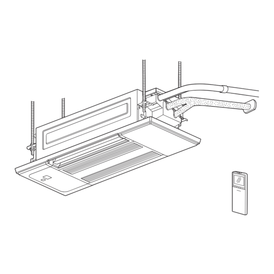
PART NAMES AND FUNCTIONS INDOOR UNIT NTXUKS06A112AA Horizontal vane Air inlet Vertical vane Air outlet Intake grille Air fi lter (Air purifying fi lter) Air cleaning fi lter (Anti-allergy Enzyme Filter, option) Spec name plate Safety strings Display section Operation indicator lamp... -
Page 4: Specification
SPECIFICATION 1. Multi connection NTXUKS06A112AA Indoor model Power supply V, phase, Hz 208/230, 1, 60 Max. fuse size (time delay)/ Disconnect switch COOL Dry (Wet) CFM 198 - 184 - 166 - 152 Airflow High - Med. - Low - SLow... - Page 5 1 ft./s., (CFM) (ft./s.) (ft.) when air is blown out horizontally from HEAT 14.6 17.6 the unit properly at the High speed posi- NTXUKS06A112AA 15.6 18.8 tion. COOL — — — The coverage should be used only as a...
-
Page 6: Outlines And Dimensions
OUTLINES AND DIMENSIONS NTXUKS06A112AA Unit: inch INDOOR UNIT (TLP-448W/ALP-448W) OBHT922A... -
Page 7: Wiring Diagram
WIRING DIAGRAM INDOOR UNIT NTXUKS06A112AA NOTES : 1.About the outdoor side electric wiring refer to the outdoor unit electric wiring diagram for servicing. 2.Use copper conductors only. (For field wiring) 3.Symbols below indicate. : Terminal : Connector block REMARQUES : 1.Pour le câblage électronique côté... -
Page 8: Refrigerant System Diagram
REFRIGERANT SYSTEM DIAGRAM INDOOR UNIT NTXUKS06A112AA Unit: inch(mm) Refrigerant pipe ø3/8(ø9.52) (with heat insulator) Indoor coil thermistor Indoor heat RT12 (main) exchanger Flared connection Indoor coil thermistor RT13 (sub) Room temperature thermistor RT11 Flared connection Refrigerant flow in cooling Refrigerant pipe ø1/4(ø6.35) -
Page 9: Service Functions
SERVICE FUNCTIONS NTXUKS06A112AA 7-1. TIMER SHORT MODE • For service, the following set time can be shortened by bridging the timer short mode point on the electronic control P.C. board. (Refer to 9-7.) • The set time for the ON/OFF timer can be reduced to 1 second for each minute. - Page 10 7-3. AUTO RESTART FUNCTION When the indoor unit is controlled with the remote controller, the operation mode, the set temperature, and the fan speed are memorized by the indoor electronic control P.C. board. “AUTO RESTART FUNCTION” automatically starts operation in the same mode just before the shutoff of the main power. Operation If the main power has been cut, the operation settings remain.
- Page 11 7-4. P.C. BOARD MODIFICATION FOR CHANGING AIRFLOW VOLUME Change Slide switch SW3 setting according to the height of ceiling. Slide switch SW3 Normal Increase airflow volume Ceiling height 8.0 ft. (2.4 m) or below above 8.0 ft. (2.4 m) and 9.0 ft. (2.7 m) or below NOTE: When the ceiling is above 9.0 ft.
-
Page 12: Microprocessor Control
MICROPROCESSOR CONTROL NTXUKS06A112AA WIRELESS REMOTE CONTROLLER Operate the remote control- ler in the area where signal is Signal transmitting section received, and beep is heard. Distance of signal: About 20 ft. (6 m) Beep(s) is (are) heard from the indoor unit when the 90°... - Page 13 8-1. COOL ( ) OPERATION (1) Press OFF/ON (stop/operate) button. OPERATION INDICATOR lamp of the indoor unit turns on with a beep tone. (2) Select COOL mode with Operation select button. (3) Press Temperature buttons TEMP button to select the desired temperature. The setting range is 61 - 88°F (16 - 31°C).
- Page 14 NOTE 2 FOR MULTI SYSTEM AIR CONDITIONER OUTDOOR UNIT: MXZ series Multi system air conditioner can connect 2 or more indoor units with one outdoor unit. • When you try to operate 2 or more indoor units with one outdoor unit simultaneously, one for the cooling and the others for heating, the operation mode of the indoor unit that operates first is selected.
- Page 15 (6) SWING ( ) mode By selecting SWING mode with VANE CONTROL button, the horizontal vanes swing vertically. When COOL, DRY or FAN mode is selected, only the upper vane swings. (7) Cold air prevention in HEAT operation The horizontal vane position is set to Upward. (8) ECONO COOL ( ) operation (ECONOmical operation) When ECONO COOL button is pressed in COOL mode, set temperature is automatically set 4°F(2°C) higher by microprocessor.
- Page 16 8-8. TIMER OPERATION 1. How to set the time (1) Check that the current time is set correctly. NOTE: Timer operation will not work without setting the current time. Initially “0:00” blinks at the current time display of TIME MONITOR, so set the current time correctly with CLOCK SET button. How to set the current time (a) Press the CLOCK set button.
- Page 17 8-9. WEEKLY TIMER OPERATION • A maximum of 4 ON or OFF timers can be set for individual days of the week. • A maximum of 28 ON or OFF timers can be set for a week. E.g. : Runs at 75°F (24°C) from waking up to leaving home, and runs at 81°F (27°C) from getting home to going to bed on weekdays.
- Page 18 (4) Press button to complete and transmit the weekly timer setting. which was blink- ing goes out, and the current time will be displayed. NOTE: • Press button to transmit the setting information of weekly timer to the indoor unit. Point the remote controller toward the indoor unit for 3 seconds.
- Page 19 8-11. SLEEP ( ) OPERATION 1. How to set SLEEP operation (1) Press OFF/ON (stop/operate) button. (2) Select COOL, DRY, HEAT or FAN mode. (3) Press SLEEP ( ) button. (4) PRESS Temperature buttons [ (Increase) and (Decrease) ] to set the temperature of SLEEP operation.
- Page 20 8-12. EMERGENCY/TEST OPERATION In the case of test run operation or emergency operation, use the emergency operation switch on the right side of the indoor unit. Emergency operation is available when the remote controller is missing or has failed, or the batteries in the remote controller are running down.
-
Page 21: Troubleshooting
TROUBLESHOOTING NTXUKS06A112AA 9-1. CAUTIONS ON TROUBLESHOOTING 1. Before troubleshooting, check the following: 1) Check the power supply voltage. 2) Check the indoor/outdoor connecting wire for miswiring. 2. Take care of the following during servicing 1) Before servicing the air conditioner, be sure to turn off the unit first with the remote controller, and then after confirming the horizontal vane is closed, turn off the breaker and/or disconnect the power plug. - Page 22 9-2. FAILURE MODE RECALL FUNCTION Outline of the function This air conditioner can memorize the abnormal condition which has occurred once. Even though LED indication listed on the troubleshooting check table (9-4.) disappears, the memorized failure details can be recalled. 1.
- Page 23 2. Flow chart of the detailed outdoor unit failure mode recall function Operational procedure The outdoor unit might be abnormal. Check if outdoor unit is abnormal according to the following procedures. Make sure that the remote controller is set to the failure mode recall function.
- Page 24 3. Table of indoor unit failure mode recall function NOTE: Blinking patterns of this mode differs from the ones of Troubleshooting check table (9-4.). Left lamp of Right lamp of Abnormal point OPERATION OPERATION Condition Remedy (Failure mode) INDICATOR lamp INDICATOR lamp Not lit Not lit...
- Page 25 9-3. INSTRUCTION OF TROUBLESHOOTING Start Indoor unit Indoor unit Indoor unit operates. OPERATION INDICATOR operates. does not receive Outdoor unit does not lamp on the indoor unit is Outdoor unit the signal from operate normally. blinking on and off. does not remote controller.
- Page 26 9-4. TROUBLESHOOTING CHECK TABLE OPERATION INDICATOR · Blinking of OPERATION INDICATOR lamp (left-hand side lamp) indicates abnormalities. Blinking Not lit NOTE: Before taking measures, make sure that the symptom reappears for accurate troubleshooting. Self check table Abnormal Operation indicator lamp Symptom Condition Remedy...
- Page 27 NOTE: When the indoor unit has started operation and the above failures are detected (the first detection after the power ON), the indoor electronic control P.C. board turns OFF the indoor fan motor with OPERATION INDICATOR lamp blinking. 9-5. TROUBLESHOOTING CRITERION OF MAIN PARTS NTXUKS06A112AA Part name Check method and criteria...
- Page 28 9-6. TROUBLESHOOTING FLOW When the left lamp of OPERATION INDICATOR lamp blinks 3 times and the right lamp of OPERATION INDICATOR lamp is not lighted. Indoor fan does not operate. Check of indoor fan motor The indoor fan motor error has occurred, and the indoor fan does not operate. Turn OFF the power supply.
- Page 29 Indoor unit operates by pressing the emergency operation switch, but does not operate with the remote controller. Check of remote controller, receiver P.C. board and indoor electronic control P.C. board * Check if the remote controller is exclusive for this air conditioner. Press OFF/ON (stop/operate) but- ton on the remote controller.
- Page 30 The unit cannot be operated with the remote controller. Also, OPERATION INDICATOR lamp does not light up by pressing the emergency operation switch. Check of indoor electronic control P.C. board and indoor fan motor Turn OFF the power supply. Remove indoor fan motor connector CN211 and vane Turn OFF the power supply.
- Page 31 When the left lamp of OPERATION INDICATOR lamp blinks ON and OFF in every 0.5-second. Outdoor unit does not operate. How to check miswiring and serial signal error Turn OFF the power supply. Is there rated voltage of Check the power 208/230 V AC in the power supply.
- Page 32 When the left lamp of OPERATION INDICATOR lamp blinks 9-time. Indoor unit and outdoor unit do not operate. Check of drain sensor and drain pump The drain sensor error Are the relay connectors of the Replace the Connect the has occurred. drain sensor (near the drain drain sensor.
- Page 33 Electromagnetic noise enters into TV sets or radios Is the unit grounded? Ground the unit. Is the distance between the antennas Extend the distance between the antennas and and the indoor unit within 9.91 ft. (3m), the indoor unit, and/or the antennas and the or is the distance between the antennas outdoor unit.
- Page 34 Factory setting 9-7. TEST POINT DIAGRAM AND VOLTAGE (Do not change the setting.) NTXUKS06A112AA SW101 Indoor electronic control P.C. board NR11 CN1N1 CN202 Varistor Connector to drain pump Serial signal R111 F11 FUSE T3.15AH250V CN201 Power supply input 208/230 V AC...
-
Page 35: Disassembly Instructions
Pull the terminal while pull out the terminal slowly. pushing the locking lever. Locking lever Connector NTXUKS06A112AA : Indicates the visible parts in the photos/figures. : Indicates the invisible parts in the photos/figures. NOTE: Turn OFF the power supply before disassembly. OPERATING PROCEDURE... - Page 36 OPERATING PROCEDURE PHOTOS/FIGURES 2. Removing the grille Figure 5 (1) Remove the intake grille. (2) Remove the fixing screws for side panels (2 screws) on Shaft the left and right sides (Figure 5). (3) Open the side panels on the left and right sides. Slide Remove the safety strings from the grille and remove inward.
- Page 37 OPERATING PROCEDURE PHOTOS/FIGURES (7) Install the screw cap. Figure 9 (8) After attaching the safety strings for the left and right side panels to the grille, install the side panels (Figure NOTE: Make sure that the tabs of the side panels securely fit Attach to the into place (Figure 9).
- Page 38 OPERATING PROCEDURE PHOTOS/FIGURES 3. Removing the indoor electric control P.C. board, Photo 2 Fixing screws the receiver P.C. board and the display P.C. of the lamp cover Drain pan board Fixing screw of the electrical box (1) Remove the intake grille. (2) Remove the side panel (L).
- Page 39 OPERATING PROCEDURE PHOTOS/FIGURES 6. Removing the drain pump and drain sensor Photo 5 (1) Remove the grille. Connector of the Connector of (2) Remove the drain pan. drain sensor the drain pump (3) Disconnect the connector of the drain pump (Photo 5). (4) Disconnect the connector of the drain sensor (Photo 5).
- Page 40 MITSUBISHI ELECTRIC TRANE HVAC US LLC HEAD OFFICE: 1340 SATELLITE BOULEVARD, SUWANEE, GA 30024, USA © Copyright 2022 MITSUBISHI ELECTRIC CORPORATION Issued: Oct. 2023. No. OBHT922 REVISED EDITION-A Published in May 2022. No. OBHT922 Specifications are subject to change without notice.