
Summary of Contents for PAC PAC-350WM
- Page 1 HIGH-EFFICIENCY, HEAT-RECOVERY VENTILATION UNITS TEL: +44(0)161 926 8346 WEB: www.pacventilation.com COMPANY: PAC Ventilation Ltd ADDRESS: Market Court, 20-24 Church Street, Altrincham, WA14 4DW...
- Page 2 PAC-350WM Installation, operation & maintenance instructions DO NOT THROW AWAY...
- Page 3 IMPORTANT SAFETY INFORMATION – PLEASE READ THESE INSTRUCTIONS CAREFULLY PRIOR TO COMMENCING INSTALLATION Responsibility for the correct and safe installation rests with the installer. Read through the full manual prior to installation. Make sure there is sufficient space to install the unit for effective operation and to ensure access for maintenance and servicing.
- Page 4 Introduction The PAC-350WM is a wall mounted heat recovery ventilation unit designed for use within small commercial environments. It provides fresh air for building occupants (as determined by building regulations) in addition to having the boost functionality to provide a purge ventilation cycle when required.
- Page 5 Control panel layout...
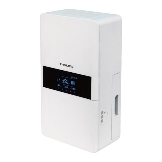
- Page 6 Unit diagram Supply air discharge LCD touch screen control panel Supply air filter housing (primary and secondary air filters) CO2, humidity, PM2.5 & temperature sensors Extract air intake Supply air blank panel for changing the filter handing Supply air discharge filter Extract air filter Heat exchange unit Unit dimensions...
- Page 7 Dimensions Duct sizes Height – mm Supply air – mm Depth – mm Exhaust air – mm Width – mm Weight – kg...
-
Page 8: Installation
Installation Use the supplied template to mark and make the holes in the external wall for the ducts from the rear of the unit. Use the template to make the 4 no holes for the fixing screws for the unit. Ensure the screws and fixings have the strength to support the weight of the unit and check that the wall is strong enough to hang the unit. - Page 9 Unit setting out Minimum clearance for installing the unit are to be as per the diagram above Changing the filter access The filter access can swap sides if maintenance access is a problem with the filter housing in its default factory location. Remove the supply air filter by sliding out the filter housing on the side of the unit.
- Page 10 Installation of duct wall termination kit: Supply air duct: 150 width with external louvre Extract air duct: 125 width with external louvre Measure the width of the wall through the hole formed for either duct: Cut the plastic ducts (supply & extract) to size (length x) with a hacksaw. Fix the external louvres to the plastic ducts with silicon.
- Page 11 Control Instructions 1.ON and OFF switch Press the on/off switch key to start or turn off the device. Press the on/off button again to activate the touch screen LCD. 2.Mode Switch The default mode when the unit is turned on is manual. In manual mode, the supply air volume and return air volume can be set by the user.
- Page 12 3 Air volume adjustment The air volume can only be operator adjusted in manual mode. In manual mode, a short press on the 'up' button and the supply air volume will flash. Press the up or down key to increase the air volume (up to 300m3/hr) in increments of 10m3/hr to the required level.
- Page 13 03 Press the up / down switch to turn the weekend programme on or off. If on is selected scroll through the six programme times to turn the unit on or off and set the time for each mode accordingly. 04 Press up and down between 1 to 7 to set the work day (Monday being 1);...
-
Page 14: Maintenance
Maintenance PRIOR TO ANY MAINTENANCE WORK, THE UNIT MUST BE ISOLATED AT SOURCE The filters will need cleaning on a regular basis. It is recommended (dependent on usage and the environment) to clean the supply air filters every 3 months. Slide out the supply air filter housing and remove both filters. - Page 15 It is recommended (dependent on usage and the environment) to clean the heat exchange unit every 6months. Remove the magnetic top front panel and remove the 6 no screws as below to access the heat exchanger – remove the screws holding the heat exchanger in place. Picture of removing magnetic top panel Pull the heat exchanger out of the housing - clean the exchanger by brushing or...
- Page 16 Wiring diagrams...
- Page 17 E1 – communication between the display and power board is abnormal – ring PAC for a service engineer or replacement if the unit is within warranty E4 – the sensor board is faulty – ring PAC for a service engineer or replacement if the unit is within warranty...
- Page 18 TECHNICAL SPECIFICATIONS AIRFLOW ELECTRICAL Supply air volume – m3/hr Supply fan – A Extract air volume – m3/hr Extract fan – A Total run current – A SUPPLY FAN Voltage 220V / 50Hz Connection 3 pin plug Fan type DC Plug Fan motor DC Internal HEAT EXCHANGER...
- Page 19 +44(0)161 926 8346 www.pacventilation.com PAC Ventilation Ltd, Market Court, 20-24 Church Street, Altrincham, WA14 4DW...