Table of Contents
Advertisement
Quick Links
Advertisement
Table of Contents

Related Manuals for ABB SCU200


Summary of Contents for ABB SCU200
- Page 1 INSITE ENERGY MANAGEMENT SYSTEM SCU200 User manual...
-
Page 3: Table Of Contents
SCU200 INSITE ENERGY MANAGEMENT SYSTEM Table of Contents 1.General Information....................6 1.1.Use and Storage of the manual ................6 1.1.1.Storing ..........................6 1.1.2.Copyright ..........................6 1.1.3.Liability disclaimer ......................6 1.1.4.Brand ............................6 1.1.5.Meaning of symbols ......................6 1.2.Cleaning........................7 1.3.Installation to mains ....................7 1.4.Disconnection from mains or connections to mains ........7 1.5.Safety warnings .......................7... - Page 4 SCU200 INSITE ENERGY MANAGEMENT SYSTEM 4.Installation and wiring ..................28 4.1.Control unit ......................28 4.2.Power supply module ................... 31 4.3.Energy meter module...................32 4.4.Assembly of connectors, current sensors, I/O modules and smart accessories......................33 4.4.1.Assembly of current sensors ..................34 4.4.2.I/O Modules ........................36 4.4.3.Final connection ......................37...
- Page 5 SCU200 INSITE ENERGY MANAGEMENT SYSTEM 7.SCU200 communication interfaces ..............78 7.1.Modbus TCP/RTU readings..................78 7.1.1.CMS current sensor readings ..................79 7.1.2.Energy meter module readings ..................82 7.1.3.I/O modules readings ....................82 7.1.4.ABB meters readings ..................... 82 7.1.5.Modbus TCP/RTU readings ................... 83 7.2.Wireless M-Bus ...................... 84...
-
Page 6: General Information
The information contained in this document is subject to change without notice and cannot be considered as an obligation by ABB Ltd. ABB Ltd. is not liable for any errors that may appear in this document. ABB Ltd. is not liable under any circumstances for any direct, indirect, special, incidental or consequential damage of any kind that may arise from using this document. -
Page 7: Cleaning
SCU200 INSITE ENERGY MANAGEMENT SYSTEM 1.2.Cleaning Use a dry cloth. 1.3.Installation to mains Installation of device to mains shall include a switch or circuit breaker for the connection to mains. The switch or circuit breaker must be suitably located and easily reachable and must be marked as the disconnecting device for the device. -
Page 8: Cyber Security Disclaimer
ABB S.p.A. and its affiliates are not liable for damages and/ or losses related to such security breaches, unauthorized access, interference, intrusion, leakage and/or theft of data or information. -
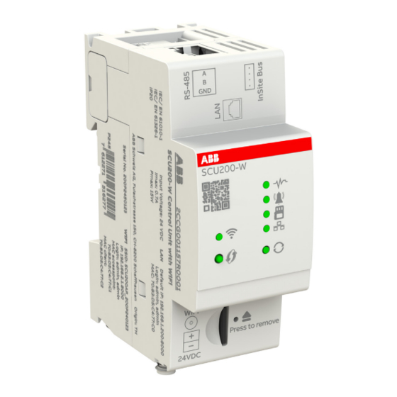
Page 9: System Overview
The system consists of a Control Unit (SCU200) and different modules easily connected through a mechanical coupling to the control unit: energy meter module (INS-E3), power supply module (INS-PS-1), Wireless M-Bus module (INS-WM), USB module (INS-USB) and smart auxiliary and signal module (INS-S/H). - Page 10 SCU200 INSITE ENERGY MANAGEMENT SYSTEM • LED status Display Function Device is off Green on Device is on Green flashing slowly Firmware is ready, Webserver is loading Orange flashing slowly Firmware updates ongoing Orange on Booting Red on Booting error Red flashing System error (e.g., lack of communication)
-
Page 11: Current Sensors
SCU200 INSITE ENERGY MANAGEMENT SYSTEM 2.2.Current sensors CMS - Bus CMS - Bus interface interface Opening for the electrical conductor Push button Push button • Current sensors LED Status Display Function Sensor is online and in measurement mode. There is a feature in the configuration to switch off the LED of all the sensors after a specified time. -
Page 12: Sensors Overview
SCU200 INSITE ENERGY MANAGEMENT SYSTEM 2.2.1.Sensors overview InSite energy management system, SMISSLINE S800 DIN rail Cable tie Mounting for all MCBs, for MCBs (S200, for fuse for all S800 universally universally method RCDs, SMISSLINE) holders devices with usable usable RCBOs... -
Page 13: I/O Modules
SCU200 INSITE ENERGY MANAGEMENT SYSTEM 2.3.I/O modules The range of I/O modules is composed of: • Input Module with 4 inputs • Output Module with 4 outputs • Input and Output Module with 2 inputs and 2 outputs InSite-bus Interface... -
Page 14: Power Supply Modules
SCU200 INSITE ENERGY MANAGEMENT SYSTEM 2.4.Power supply modules LATERAL VIEW FRONT VIEW Modular bus Modular bus connector (output) connector (input) Status LED TOP VIEW AC power input N L1 • LED Display Function Device is off Green on Device is on... -
Page 15: Energy Meter Module
SCU200 INSITE ENERGY MANAGEMENT SYSTEM 2.5.Energy meter module FRONT VIEW TOP VIEW BOTTOM VIEW Modular bus Voltage CTS current transformers for connector (output) measurement CT1 (L1), CT2 (L2), CT3 (L3) L1, L2, L3, N Status LED kWh pulses LED LATERAL VIEWS... -
Page 16: Communication Modules
SCU200 INSITE ENERGY MANAGEMENT SYSTEM 2.6.Communication modules 2.6.1.Wireless M-Bus module FRONT VIEW Modular bus connector (output) Status LED Connection LED Modular bus connector (input) LATERAL VIEWS Modular bus connector (output) SMA connector (external antenna) • LED status Display Function Device is off... -
Page 17: Usb Module
(P1 port) • LED status Display Function Device is off Green on Device is ON • LED USB Display Function Green on USB bus is ready for operation Red on USB ports error (e.g. port overcurrent, lack of connection with SCU200) -
Page 18: Smart Accessories
SCU200 INSITE ENERGY MANAGEMENT SYSTEM 2.7.Smart accessories 2.7.1.Smart signal/auxiliary contact FRONT VIEW Assignment button Connection LED Status LED TOP VIEW Modular BUS connector • LED status Display Function Blue on Assignment ok No power supply Slow blinking Normal mode, no Modbus assigned... -
Page 19: Insite Accessories
SCU200 INSITE ENERGY MANAGEMENT SYSTEM 2.8.InSite accessories • InSite Flat Cable The INS105 flat cable is a 4-pin cable for connecting multiple sensors and I/O modules to one control unit. Please take into account that possible cable length of the InSite flat cable depends on the number and shape of sensors, and on the number of I/O modules connected. -
Page 20: Technical Characteristics / Specifications
SCU200 INSITE ENERGY MANAGEMENT SYSTEM 3.Technical characteristics / specifications 3.1.Technical data - control unit 35,8 Technical feature Unit Description WIFI Supply voltage [VDC] 24 +/- 10% Current Max 0.7 Connection InSite modular bus 2.5 ... 15 (depending on the CPU load,... -
Page 21: Overall Dimensions And Technical Data I/O Modules
SCU200 INSITE ENERGY MANAGEMENT SYSTEM 3.2.Overall dimensions and technical data I/O modules 35,8 Input module Output module Input and Output DM11 DM00 module DM10 2 Input + 2 Number of digital channels 4 Input 4 Output Output active input: active input:... -
Page 22: Compatible Devices
3.2.1.Compatible devices Devices compatible with I/O Modules include Molded Case Circuit Breakers (MCCBs), accessories of DIN- Rail protection devices, overvoltage Protection devices and meters pulse output. • ABB ranges compatible with I/O Modules are: Molded Case Circuit Breaker Tmax XT... -
Page 23: Overall Dimensions And Technical Data - Insite Modules
SCU200 INSITE ENERGY MANAGEMENT SYSTEM 3.3.Overall dimensions and technical data - InSite modules 3.3.1.Power supply module 17,5 Technical feature Unit Description 100...240 VAC +/-10% Supply voltage 110...350 VDC (tolerance included) Connection Solid conductor 0.14 ... 1.5 AWG solid conductor [AWG]... -
Page 24: Energy Meter Module
SCU200 INSITE ENERGY MANAGEMENT SYSTEM 3.3.2.Energy meter module 17,5 Technical feature Unit Description Supply voltage [VDC] Supplied by the InSite modular bus Connection InSite modular bus Power consumption Network type Three phase + N Voltage input connection Screwless terminal block... -
Page 25: Wireless M-Bus Module
SCU200 INSITE ENERGY MANAGEMENT SYSTEM 3.3.3.Wireless M-Bus module 17,5 Technical feature Unit Description Supply voltage [VDC] Supplied by the InSite modular bus Connection InSite modular bus Power consumption Communication protocol Wireless M-Bus RF mode C1 and T1 Frequency band [MHz] 868.95... -
Page 26: Usb Module
SCU200 INSITE ENERGY MANAGEMENT SYSTEM 3.3.4.USB module 17,5 Technical feature Unit Description Supply voltage [VDC] Supplied by the InSite modular bus Connection InSite modular bus Power consumption 0.4 (standby) Communication protocol USB 1.1 (max speed 12Mbps) 100mA @5V (USB P1 port) -
Page 27: Smart Auxiliary And Signal Contact
SCU200 INSITE ENERGY MANAGEMENT SYSTEM 3.3.5.Smart auxiliary and signal contact Technical feature Unit Description SSD Supply voltage [VDC] Supplied by the InSite modular bus Connection InSite modular bus Power loss Mounting Position Right S2CHR (x2) Pluggable accessories S2C-S/HR (x2) Miniature Circuit Breaker... -
Page 28: Installation And Wiring
SCU200 INSITE ENERGY MANAGEMENT SYSTEM 4.Installation and wiring • Warranty Safe operation is ensured if assembly work has been carried out according to these user instructions. Furthermore, the instructions in the manual must be observed. • Authorized Personnel Assembly, connection, and removal work should only be carried out by authorized and qualified personnel. - Page 29 AWG 28-16 8...9 mm max. 1 mm AWG 28-17 10 mm To supply the SCU200 with 24 VDC, first connect the cables to the adapter and then plug this is in the connection port to 24 VDC of the SCU200.
- Page 30 InSite expansion module. Put attention to the correct interlocking between modules. Attention: In case one or more expansion modules have to be added to SCU200 / SCU200-W plug them all first before assemblying on DIN-Rail bar.
-
Page 31: Power Supply Module
SCU200 INSITE ENERGY MANAGEMENT SYSTEM 4.2.Power supply module • Wiring After mounting the modules on DIN RAIL, proceed with the connection of the cables. Supply voltage must not exceed 240 VAC and 350 VDC. max. 1.5 mm AWG 28-16 8 ... 9 mm •... -
Page 32: Energy Meter Module
SCU200 INSITE ENERGY MANAGEMENT SYSTEM 4.3.Energy meter module • Wiring Connect the number of phases desired to the voltage measurement inputs. It is desirable to use L1 & N for one phase network and L1, L2, L3 & N for three phase with neutral network. -
Page 33: Assembly Of Connectors, Current Sensors, I/O Modules And Smart Accessories
3. Insert the connector into the connector housing at the marked position. 4. Press together using parallel pliers. Repeat the process at all other marks. Attention: In case one or more expansion modules have to be added to SCU200 / SCU200-W plug them all first before assemblying on DIN-Rail bar. -
Page 34: Assembly Of Current Sensors
• Mounting of InSite energy management system and SMISSLINE Sensors Sensors fit to all ABB installation devices with twin terminals. Flat cable should not exert force on the sensor, otherwise measuring errors may occur. - Page 35 SCU200 INSITE ENERGY MANAGEMENT SYSTEM • Mounting Sensors on DIN-Rails Sensors can be mounted on all 35-mm DIN-Rails (DIN50022). The cable should not exert force on the sensor, otherwise measuring errors may occur. 1. Snap in the bracket on the DIN-rail.
-
Page 36: I/O Modules
SCU200 INSITE ENERGY MANAGEMENT SYSTEM 4.4.2.I/O Modules • Assembly on 35mm DIN-Rail To assemble of the control unit, perform steps 1 and 2. The device can be mounted horizontally or vertically. To disconnect, perform steps 3, 4 and 5. • Wiring Connection of input and output channels to accessories and external devices is represented in the figure below. -
Page 37: Final Connection
SCU200 INSITE ENERGY MANAGEMENT SYSTEM For output channels external power supply with overcurrent protection (by fuse or internal functionality) is required. - 24VDC is maximum value of DC, can also be lower. - 230VAC is maximum value of AC, can also be lower. -
Page 38: Access To Control Unit And Configuration Wizard
Defining the port number is important because without a port number access is not possible. Attention: In case of DHCP, the system administrator can read the IP address assigned to the SCU200 device by DHCP on the router.. -
Page 39: Direct Lan Connection
192.168.1.200:8000 / Subnet Mask: 255.255.255.0 The control unit is set up using a web interface. To connect a PC or laptop to the SCU200 without DHCP, you need to configure the LAN interface with a static IP address. Using the example of Windows, the following shows the configuration steps. -
Page 40: Wifi
To connect to such a network in an easy way, you need to turn on the Wi-Fi interface on the SCU200 and click the WPS button. Then the Wi-Fi LED will start blinking green and a time window will open for 2 minutes, during which we must press the WPS button on the access point. -
Page 41: Control Unit Login
SCU200 INSITE ENERGY MANAGEMENT SYSTEM 5.2.Control unit login The web user interface is designed for use on browser-based devices. The recommended web browser is Google Chrome, other supported web browsers are Safari, Firefox, Opera, Internet Explorer. Start screen (login) Insert the IP address of the device in the browser address bar. -
Page 42: Wizard
SCU200 INSITE ENERGY MANAGEMENT SYSTEM 5.3.Wizard During Wizard configuration it is possible to do basic configuration of SCU and assign connected devices. To enter the wizard, it is required to login to WebUI. 1. Credentials - The first mandatory step is to set new credentials. The new password must contain a minimum of 8 characters, at least one uppercase letter and one number. -
Page 43: Webui
SCU200 INSITE ENERGY MANAGEMENT SYSTEM 6.WebUI 6.1.Structure 1. Homepage A. Asset overview B. Contracts 2. Energy monitoring C. Historical values a. Import D. Import/export b. Export a. I/O modules A. Control 3. Load management b. MOD & AR B. Automations a. -
Page 44: Homepage
SCU200 INSITE ENERGY MANAGEMENT SYSTEM 6.2.Homepage In the Homepage section it is possible to create and customize different dashboards in order to have an immediate and easily visible summary of the desired set of measurement data. This data can be displayed in various forms depending on the selected widget, it can be in the form of a table or a graphical chart. -
Page 45: Energy Monitoring
SCU200 INSITE ENERGY MANAGEMENT SYSTEM 6.3.Energy monitoring 6.3.1.Asset overview In the Asset overview section, it is possible to customize a single dashboard in order to have an immediate and easily visible summary of the desired set of measurement data. This data can be displayed in various forms depending on the selected widget, it can be in the form of a table or a graphical chart. -
Page 46: Contracts
SCU200 INSITE ENERGY MANAGEMENT SYSTEM 6.3.2.Contracts This page allows you to create or remove Contracts and Tariffs. By clicking on “Add new contract”, it is possible to create a new contract. One contract can be assigned to single tag related to: energy, water or... -
Page 47: Historical Values
SCU200 INSITE ENERGY MANAGEMENT SYSTEM 6.3.3.Historical values Here it is possible to visualize the “Historical values” of different measurements according to the category or group selected. Data type resolution depends on the device and it binds the maximum time interval that can be shown. -
Page 48: Load Management
SCU200 INSITE ENERGY MANAGEMENT SYSTEM 6.4.Load management 6.4.1.Control Here it is possible to change the status (open/close) of each single output port of the active I/O modules. A confirmation message is shown before completing the action. -
Page 49: Automations
SCU200 INSITE ENERGY MANAGEMENT SYSTEM 6.4.2.Automations This page allows to set automatic actions on selected devices if a specific configured event occurs. It is possible to add up to two conditions per single automation. Available logical operators for multiple conditions are “AND”, “OR”. - Page 50 SCU200 INSITE ENERGY MANAGEMENT SYSTEM Conditions Logical Select logical operator (only for multiple conditions) Device type Select the type of the device Select the device already defined in “My plant - Devices” according to Device the Device type selected “Cross-up”, “Cross-down”, “Communication failure” and “Communication restore”.
-
Page 51: My Plant
SCU200 INSITE ENERGY MANAGEMENT SYSTEM 6.5.My plant 6.5.1.Site plan view 6.5.2.Groups This page allows you to create or remove groups of devices. By clicking on “Add new group”, it is possible to create a new group by selecting the type of devices. - Page 52 SCU200 INSITE ENERGY MANAGEMENT SYSTEM • Current sensors Create a new sensor Modbus ID and then assign it to the physical sensor by Add and assign new current sensor clicking the pushbutton of the sensor (Note: Wait for confirmation before assigning the next sensor).
- Page 53 SCU200 INSITE ENERGY MANAGEMENT SYSTEM • I/O modules Create a new I/O module Modbus ID and then assign it to the physical module by clicking the pushbutton Add and assign new I/O module of the I/O module (Note: Wait for confirmation before assigning the next I/O module).
- Page 54 SCU200 INSITE ENERGY MANAGEMENT SYSTEM I/O Modules Definitions Modbus ID I/O module identification number I/O module It is automatically recognized when the module is added and assigned. type I/O module It is possible to define the module name name Port...
- Page 55 SCU200 INSITE ENERGY MANAGEMENT SYSTEM • INS-S/H Create a new INS-S/H Modbus ID and then assign it to the physical module Add and assign new INS-S/H by clicking the pushbutton of the INS-S/H (Note: Wait for confirmation before assigning the next INS-S/H).
- Page 56 SCU200 INSITE ENERGY MANAGEMENT SYSTEM • Modbus RTU devices In this section it is possible to add Modbus RTU devices connected to the SCU200. It is possible to download device descriptor with registers that was configured or upload previously prepared/configured descriptor.
- Page 57 SCU200 INSITE ENERGY MANAGEMENT SYSTEM Modbus RTU Definitions Address Assign register address (between 0 and 65535). Category Select the predefined category of the register or add new. Select the predefined register or add new. For predefined registers Value some fields are already filled and can't be changed.
- Page 58 SCU200 INSITE ENERGY MANAGEMENT SYSTEM • Modbus TCP devices In this section it is possible to add Modbus TCP devices connected to the SCU200. It is possible to download device descriptor with registers that was configured or upload previously prepared/configured descriptor.
- Page 59 SCU200 INSITE ENERGY MANAGEMENT SYSTEM Modbus TCP devices Definitions Address Assign register address (between 0 and 65535). Category Select the predefined category of the register or add new. Select the predefined register or add new. For predefined registers Value some fields are already filled and can't be changed.
- Page 60 SCU200 INSITE ENERGY MANAGEMENT SYSTEM • Wireless M-Bus Wireless M-Bus modules that are connected to SCU200 are automatically autoassigned during system startup. It is possible to clear Modbus IDs of devices that are already assigned, then confirmation of device reboot needed is displayed.
-
Page 61: Diagnostic
SCU200 INSITE ENERGY MANAGEMENT SYSTEM 6.6.Diagnostic 6.6.1.Events log Here it is possible to show all the events that occurred in the paginated table. Rows can be sorted and/or filtered by clicking headers and selecting desired value from drop-down lists. Events must previously be set in the “Diagnostic -> Configuration” page. -
Page 62: Configuration
SCU200 INSITE ENERGY MANAGEMENT SYSTEM 6.6.3.Configuration This page allows you to set events. When a new device is added the events “Communication failure” and “Communication restore” are automatically configured in order to monitor the connection status for that device. If an event occurs, it is shown in the “Diagnostic – Events log” section. An event can occur... -
Page 63: System Setup
NTP server. Check the internal time of the device to guarantee correct operation of the SCU200. If it is incorrect, it must be set manually. Please keep attention: incorrect date and time settings may cause device malfunction. - Page 64 SCU200 INSITE ENERGY MANAGEMENT SYSTEM • System In this section it is possible to carry out a system reset (to restart the device with the current settings), to restore the default settings, to carry out a safe shutdown and mount/unmount card.
-
Page 65: Communication
SCU200 INSITE ENERGY MANAGEMENT SYSTEM • UI aspect ithems In this section it is possible to change the appearance of the WebUI - you can set a light or dark theme 6.7.2.Communication • IP The following information have to be set to correctly have access to the user interface via IP:... - Page 66 SCU200 INSITE ENERGY MANAGEMENT SYSTEM • WIFI Here you can manage Access Point and WiFi Settings. It is possible to Enable/Disable Access point and WPS for access point. With Enabled WiFi it is possible to select WiFi network, then provide password if it is needed. Also, configuration of WiFi IP address is possible and change of antenna selection (internal/external).
- Page 67 POST /api/v1/data The endpoint allows you to get online and historical data from SCU200. Variables must be provided in a JSON body of a POST request. Variables can be read from device descriptors or metadata endpoint. Object ids can be read from metadata endpoint.
- Page 68 SCU200 INSITE ENERGY MANAGEMENT SYSTEM //”type”: online or historical “type”: “online”, “values”: { // object_id: [variables] “415”: [“currentTrms”, “currentAc”, “currentDc”], “389”: [“voltageL1”] //”begin_timestamp”: only for historical “begin_timestamp”: 1663231649, //”end_timestamp”: only for historical “end_timestamp”: 1663318059, //”resolution”: only for historical, possible values ‘30s’, ‘15min’, ‘1h’, ‘1d’, ‘1m’, maximum date range is 1000 samples per period (or 12 for 1m)
- Page 69 SCU200 INSITE ENERGY MANAGEMENT SYSTEM Historical values e.g. “data”: [ “values”: { “415”: [“currentTrms”, “currentAc”, “currentDc”], “389”: [“voltageL1”] “type”: “historical”, “begin_timestamp”: 1669770000, “end_timestamp”: 1669794623, “resolution”: “1h” Response: “id”: “scu200hs”, “ip”: “192.168.1.200”, “data”: [ “timestamp”: 1669791600, “values”: { “389”: { “voltageL1”: “-”...
- Page 70 SCU200 INSITE ENERGY MANAGEMENT SYSTEM “415”: { “currentTrms”: 0.11546389013528824, “currentAc”: 0.07456666976213455, “currentDc”: 0.08336666971445084 “timestamp”: 1669784400, “values”: { “389”: { “voltageL1”: 246.45889282226562 “415”: { “currentTrms”: 0.11598055809736252, “currentAc”: 0.07455277442932129, “currentDc”: 0.08405833691358566 “timestamp”: 1669780800, “values”: { “389”: { “voltageL1”: 247.96444702148438 “415”: { “currentTrms”: 0.11795832961797714, “currentAc”: 0.07485000044107437,...
- Page 71 SCU200 INSITE ENERGY MANAGEMENT SYSTEM “timestamp”: 1669773600, “values”: { “389”: { “voltageL1”: 249.10472106933594 “415”: { “currentTrms”: 0.11900000274181366, “currentAc”: 0.07471388578414917, “currentDc”: 0.0877000018954277 “timestamp”: 1669770000, “values”: { “389”: { “voltageL1”: 249.11721801757812 “415”: { “currentTrms”: 0.11949722468852997, “currentAc”: 0.07449444383382797, “currentDc”: 0.08879444748163223 GET: /api/v1/certificate get current ssl certificate in response body...
- Page 72 SCU200 INSITE ENERGY MANAGEMENT SYSTEM Email Email settings are needed in order to carry out email data export Make sure communication on SMTP port 587 or 465 (SSL) is allowed in your network. • FTP You can fill the fields with server details (credentials) in order to allow automatic data export. FTP settings are needed in order to carry out FTP data export.
-
Page 73: Users
SCU200 INSITE ENERGY MANAGEMENT SYSTEM • MODBUS Here you can make changes to the Modbus TCP settings. It is possible to disable or enable Modbus TCP. By default, Port 502 is set by default, if needed, port number can be changed. -
Page 74: Ssl Certificate
SCU200 INSITE ENERGY MANAGEMENT SYSTEM 6.7.4.SSL certificate In this section it is possible to upload or generate a .pem file containing a private key and a public certificate in order to provide a secure connection via the web browser. • Upload Upload It is possible to browse, upload or download the currently in place certificate. - Page 75 SCU200 INSITE ENERGY MANAGEMENT SYSTEM • Generate IP address Indicates your currently configured IP address on the device Subnet mask Indicates your currently configured subnet mask on the device Gateway Indicates your currently configured gateway on the device If checked, you can generate a certificate for the whole subnet. The Select whole subnet minimal subnet mask is 255.255.252.0...
-
Page 76: Firmware Update
It is highly recommended to update the firmware to the latest version for security and functionality reasons. Please check the ABB website for current SW revision and download the latest version of the firmware. After browsing the downloaded file, please use the “Update file” button to submit the new firmware to the device. - Page 77 SCU200 INSITE ENERGY MANAGEMENT SYSTEM...
-
Page 78: Scu200 Communication Interfaces
Example: 1234h → first 12h then 34h. • Physical Interface RS-485 To communicate with the SCU200 from an upper system, all devices (masters & slaves) must have the same data rate and data format. These settings are defined over the Web UI, as described in the dedicated chapter. -
Page 79: Cms Current Sensor Readings
SCU200 INSITE ENERGY MANAGEMENT SYSTEM • Error Codes Modbus protocol defines a common way of error reporting. Every request (read or write) sent in unicast mode is expected to return a value in packet of the same structure. In case of a message delivery error (not a CRC problem but a message execution problem), the generated response contains a function code with MSB (80h) set and a single byte representing the error code, called “exception code”. - Page 80 SCU200 INSITE ENERGY MANAGEMENT SYSTEM • Values with special meanings: Calculated branch power and energy values Special values (hex) Special values (dec) Meaning FFFF 7FF0 4'294'934'512 Data pending, acquisition in progress FFFF 7FF1 … 4'294'934'513 … Reserved FFFF 7FFB 4'294'934'523...
- Page 81 SCU200 INSITE ENERGY MANAGEMENT SYSTEM • Polarity of sensors (for DC currents) These registers contain the configured nominal current value and the DC polarity information of each sensor with following bit format: 000P RRRR RRRR RRRR • R Reserved for future use •...
-
Page 82: Energy Meter Module Readings
SCU200 allows connecting up to 16 RTU devices including meters with RS-485 interface. Supported meter types are ABB M4M/M1M, M2M, DMTME, IM300, EV meters and EQ meters. Each meter can be assigned to Modbus ID from 33 to 48 and is available under My plant->Devices->Modbus RTU devices. -
Page 83: Modbus Tcp/Rtu Readings
Port 502 is used by default SCU200 acts as Modbus RTU router and has neither static registers map nor its own modbus ID. In order to query a device, user should use connection parameters, IDs, functions and addresses exactly as it would be used in case of querying a device directly. -
Page 84: Wireless M-Bus
7.2.Wireless M-Bus 7.2.1.Wireless M-bus devices readings SCU200 allows to connect up to 16 INS-WM modules ( in case of no INS-E3 modules are connected. ). They can be addressed using Modbus ID from range 49-63. Each module can be configured to listen on Wireless MBus mode C1 or T1. They are fixed to operate on 868.95MHz radio frequency. - Page 85 SCU200 INSITE ENERGY MANAGEMENT SYSTEM • Meter address [0x25] Unique meter ID from which frame was available in M-Bus data registers. It is automatically updated after read from M-Bus data registers, with next meter ID if at least one is available in device queue.
- Page 86 SCU200 INSITE ENERGY MANAGEMENT SYSTEM • Wireless M-Bus encryption Typically most of the meters sent their frames encrypted due to security reasons. INS-WM module allows to store up to 64 individual keys for decryption data. For management of security keys module use Modbus custom function requests: 0x70 –...
- Page 87 SCU200 INSITE ENERGY MANAGEMENT SYSTEM 0x75 – Check meter Function performs checking meter of key pointed by MFIELD and MID and compare this key with KEY0- 15 provided in modbus request. If key exist and is same as provided in request, response is sent back to master with function code 0x75.
- Page 88 Viale dell’Industria, 18 20009 Vittuone (MI) Italy new.abb.com/low-voltage © Copyright 2023 ABB. All rights reserved. Due to possible changes in design and materials, the features and sizes contained in this catalog re to be considered as binding only after confirmation by ABB.