Table of Contents
Advertisement
Quick Links
For Indoor Commercial Applications Only:
Single Tankless H-Series Demand Duo™
This product is NOT intended for residential applications.
CHS13080HiN . ...........80 Gallon, 130,000 BTU
CHS13080HiP . ...........80 Gallon, 130,000 BTU
CHS16080HiN . ...........80 Gallon, 160,000 BTU
CHS16080HiP . ...........80 Gallon, 160,000 BTU
CHS19980HiN . ...........80 Gallon, 199,000 BTU
CHS19980HiP . ...........80 Gallon, 199,000 BTU
CHS160100HiN . .........100 Gallon, 160,000 BTU
CHS160100HiP . .........100 Gallon, 160,000 BTU
CHS199100HiN ...........100 Gallon, 199,000 BTU
CHS199100HiP ...........100 Gallon, 199,000 BTU
Demand Duo™ H-Series Installation and Operation Manual
Advertisement
Table of Contents

Related Manuals for Rinnai Demand Duo CHS199100HiN


Summary of Contents for Rinnai Demand Duo CHS199100HiN
- Page 1 For Indoor Commercial Applications Only: Single Tankless H-Series Demand Duo™ This product is NOT intended for residential applications. CHS13080HiN ....80 Gallon, 130,000 BTU CHS13080HiP ....80 Gallon, 130,000 BTU CHS16080HiN ....80 Gallon, 160,000 BTU CHS16080HiP ....80 Gallon, 160,000 BTU CHS19980HiN .
- Page 2 If the information in these instructions is not followed exactly, a WARNING WARNING fire or explosion may result causing property damage, personal injury, or death. • Do not store or use gasoline or other flammable vapors and liquids in the vicinity of this or any other appliance.
-
Page 3: Table Of Contents
1. Welcome ........................4 2. Safety ..........................5 2.1 Safety Symbols ....................... 5 2.2 Safety Precautions ....................5 3. About ..........................7 3.1 Components ......................7 3.2 Specifications ......................8 3.3 Dimensions ......................10 4. Installation ........................12 4.1 Installation Guidelines ..................... 12 4.2 What You Will Need .................... - Page 4 Thank you for purchasing Rinnai’s Demand Duo™ H-Series Commercial Hybrid Water Heating System. This manual provides information on the installation, operation, and • You must read the entire manual to maintenance of Rinnai’s Demand Duo™ H-Series properly operate the water heater and to Commercial Hybrid Water Heating System.
-
Page 5: Safety Symbols
• Combustible construction refers to adjacent walls and ceiling and should not be confused with combustible or flammable products and Topics in this section materials. Combustible and/or flammable products and materials should never be stored • Safety Symbols in the vicinity of this or any gas appliance. •... - Page 6 • Failure to properly vent this appliance can result in death, personal injury and/or property damage. • Rinnai recommends that every home have a carbon monoxide (CO) alarm inside or directly outside each bedroom or sleeping area. Check batteries monthly and replace them annually.
-
Page 7: Components
Topics in this section • Components • Specifications • Dimensions Figure 1: Components Electric Conduit Pump Dirt Leg Gas Swivel Gas Flex Line Flare Nut Adapter Front Cover (Supplied but not installed) DuoSmart™ Digital Controller Demand Duo™ H-Series Installation and Operation Manual... - Page 8 The maximum gas supply pressure must not exceed the value specified by the manufacturer. Temperature limit of 185°F can be achieved using optional MCC-91 controller. Rinnai products are continually being updated and improved; therefore, specifications are subject to change without prior not ice. Demand Duo™ H-Series Installation and Operation Manual...
- Page 9 Table 2: Recovery Capacity / Input U.S. Gallon / HR Liters / HR at Temperature Rise Indicated Input Product °F 30°F 40°F 50°F 60°F 70°F 80°F 90°F 100°F 110°F 120°F 130°F 140°F Tank Number Type Capacity BTU/HR °C 17°C 22°C 28°C 33°C 39°C...
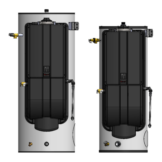
- Page 10 LEFT RIGHT Models Measurements below are CHS199100Hi shown in inches (mm). CHS160100Hi 34.77 (883) Figure 2: Dimensions Ø 28.30 (718) RIGHT FRONT LEFT 4.20 (107) 1-1/2 in. 3.40 (86) MNPT Cold Drain Demand Duo™ H-Series Installation and Operation Manual...
- Page 11 Models Measurements below are shown in inches CHS19980Hi (mm). CHS16080Hi CHS13080Hi Figure 3: Dimensions 31.86 (809) Ø 24.25 (616) RIGHT FRONT LEFT 4.19 (106)1-1/2 in. MNPT Cold 3.54 (90) Drain Demand Duo™ H-Series Installation and Operation Manual...
-
Page 12: Installation
• Should overheating occur or the gas supply training in installation of tankless water fail to shut off, turn off the manual gas control heaters. Training for Rinnai Tankless Water valve to the appliance. Heaters is accessible online at www.trainingevents.rinnai.us. -
Page 13: Venting
Pipe wrenches (x2) • Phillips Head screwdriver This section provides information on the • importance of water quality to the Rinnai Adjustable pliers Tankless Water Heater. The information is • Wire cutters intended to serve as general guidelines only and •... - Page 14 Therefore, it is recommended to install as a direct Enclosure vent (use outside air for combustion). In applications utilizing room air where there are high levels of particulates, Rinnai offers a room air screen. Strap B The water heater, venting, and vent termination (s) should not be installed in any areas where the air may contain these corrosive compounds.
- Page 15 Figure 5: Clearances IMPORTANT 0 in. Minimum 0 in. Minimum Product installed in the state of California must be braced, anchored, or otherwise secured to avoid motion or falling during an 0 in. Minimum earthquake. Contact the California Office of the State Architect located at 1102 Q Street, Suite 5100, Sacramento, CA 95811 for instructions.
- Page 16 Use this checklist to ensure you have selected the correct location for the water heater. The water heater is not exposed to □ corrosive compounds in the air. The water heater location complies with □ the required clearances. The planned combustion air and exhaust □...
-
Page 17: Venting Requirements
If it becomes necessary to access an • Engineered vent systems must be firmly enclosed vent system for service or repairs, Rinnai is not responsible for any pressed together so that the gaskets form an air tight seal. costs or difficulties in accessing the vent system. - Page 18 Check to determine whether local codes 1. Install the water heater. supersede the following clearances: 2. Determine the termination method — • horizontal or vertical, concentric, or twin Avoid termination locations near a dryer pipes, etc. vent. • 3. Determine proper location for wall or roof Avoid termination locations near penetration for each termination.
- Page 19 Three types of venting options are available: Direct Vent (Concentric Pipe and Twin Pipe) Concentric Pipe Twin Pipe Combustion air and exhaust vent directly through Combustion air and exhaust vent directly a single concentric connection. Hot exhaust exits through separate penetrations. through the interior tube, while combustion air enters through the outer layer.
- Page 20 Direct Vent (Concentric Pipe and Twin Pipe) Figure 13: Direct Vent Termination Clearances (For Concentric and Twin Pipe) TERMINATION AIR SUPPLY INLET VENT TERMINAL Clearance in Ref. A also AREA WHERE TERMINAL applies to anticipated IS NOT PERMITTTED snow line SNOW Canadian Installations U.S.
- Page 21 Direct Vent (Concentric Pipe) Figure 16 60 in. (1.52 m) Concentric Pipe Overview Note: 24 in. (0.61 m) Combustion air and exhaust vent directly through to wall or parapet a single concentric connection. Hot exhaust exits through the interior tube, while combustion air enters through the outer layer.
- Page 22 Direct Vent (Concentric Pipe) IMPORTANT Install the venting termination according to the diagrams and instructions in this manual. Concentric Pipe Installation Instructions Slope the venting 1/4 in. per foot toward the appliance according to the vent 1. Remove and discard screw from concentric manufacturer’s installation instructions.
- Page 23 Direct Vent (Twin Pipe) Figure 22 Twin Pipe Overview Combustion Combustion air and exhaust vent directly through Exhaust separate penetrations. Twin Pipe Termination Clearances Figure 23 Intake 12 in. (0.30 m) minimum Indicates area in which intake 12 in. (0.30 m) minimum cannot be located.
- Page 24 Direct Vent 3. Install the combustion air vent pipe. (Twin Pipe) Ensure it is properly seated. Secure the combustion air vent pipe to the combustion air vent connection with the Twin Pipe Installation Instructions supplied screw. Figure 26 The water heater is equipped with a 2 in. (51 mm) pipe connection.
- Page 25 Direct Vent (Twin Pipe) Twin Pipe Example Vent Applications Slope horizontal exhaust 1/4 in. per foot towards the water heater. DO NOT slope combustion air pipe towards the water heater. This configuration requires the use This configuration requires the use of a Concentric Vent Termination of a Concentric Vent Termination 2 in.
- Page 26 Non-Direct Vent (Room Air) Figure 28: Room Air Termination Clearances TERMINATION AIR SUPPLY INLET VENT TERMINAL Clearance in Ref. A also AREA WHERE TERMINAL applies to anticipated IS NOT PERMITTTED snow line SNOW Canadian Installations U.S. Installations (CSA B149.1) (ANSI Z223.1 /NFPA 54) Other than direct vent Other than direct vent Description...
- Page 27 Non-Direct Vent (Room Air) NOTE • Installation of Non-Direct Vent (Room Air) must use listed category IV venting. • All terminations (horizontal and/or vertical) must terminate 12 in. above grade or anticipated snow level. Exhaust Termination Clearances for Internal (Indoor) Room Air Applications Figure 29 12 in.
- Page 28 Non-Direct Vent Confined Space (Room Air) A confined space is defined in the National Fuel Gas Code, ANSI Z223.1/NFPA 54 as "a space whose volume is less than 50 cubic feet per Combustion Air 1000 Btu/hr (4.8 m3 per kW per hour) of the ag- gregate input rating of all appliances installed in that space."...
- Page 29 Non-Direct Vent (Room Air) IMPORTANT Combustion air provided to the appliance should not be taken from any area of the Combustion Air (Continued) structure that may produce a negative pressure (i.e. exhaust fans, powered Louvers and Grills ventilation fans). When sizing the permanent opening considera- tion must be taken for the design of the louvers or grills to maintain the required free area re- quired for all gas utilizing equipment in the...
- Page 30 Non-Direct Vent (Room Air) Figure 31 Exhaust Vent termination per ANSI Z223.1/NFPA 54. For clearances not specified in ANSI Z223.1/NFPA 54, clearances are in accordance with local installation codes and the requirements of the gas supplier. Demand Duo™ H-Series Installation and Operation Manual...
- Page 31 Non-Direct Vent 4. Place the vent screen or room air screen (Room Air) inside elbow and secure with the supplied screw. Use the room air screen for environments where room air is dusty. Non-Direct Vent (Room Air) Installation Instructions NOTE •...
- Page 32 Non-Direct Vent (Room Air) Non-Direct Vent (Room Air) Example Vent Applications 2 in. or 3 in. 2 in. or 3 in. Schedule 40 Schedule 40 PVC/CPVC PVC/CPVC Snorkel Standard Termination Upside Down "U" Vertical Configuration Termination Configuration 2 in. or 3 in. 2 in.
- Page 33 • The common vent system must only be Water Heaters to share the same vent system. installed by a trained and qualified Rinnai water heaters can only be common vented professional. with Schedule 40 PVC/CPVC or with the Rinnai certified common vent system.
- Page 34 Maximum vent length starts at the end of the header system. • Use 10 ft (3 m) as equivalent vent length for 90° elbows. Common Vent Maximum Equivalent Vent Length Rinnai Common Vent System or Schedule 40 PVC/CPVC HEADER DIAMETER 3 in. 4 in. 6 in. Water Heater...
- Page 35 Various 3 in., 4 in. and 6 in. Schedule 40 PVC/CPVC Terminations Product Diagram Description 90° Elbow 45° Elbow Rinnai Common Vent Terminations (Ubbink C-Vent) Manufacturer Phone Web Site Ubbink 800-621-9419 www.rinnai.us Product Part Number Description 790096 CVent Roof Termination 6 in.
- Page 36 • Refer to vent manufacturer’s installation in- structions for proper joint assembly proce- dures and products. • PVC/CPVC common venting should include a condensate drain and trap between the head- er and vent length. Condensate trap must include a loop that can hold 6 in. (15 cm) of PVC solvents (primer WARNING and glue) can be...
-
Page 37: Pressure Relief Valve Requirements
• The relief valve is installed near the tankless Topics in this section hot water outlet. • Pressure Relief Valve Requirements INFORMATION • Temperature - PRV Requirements If a relief valve discharges periodically, this may • Connect the Water Heater to the Water be due to thermal expansion in a closed water Supply supply system. - Page 38 Refer to Rinnai Tankless Water Heater • The HOT water outlet is a 1-1/2 in. MNPT Installation and Operation Manual for condensate fitting located at the top of the tank.
- Page 39 • A condensate neutralizer kit (Part Number: 804000074) is available from Rinnai. The kit allows condensate to flow through neutralizing media that raises the pH of the condensate to a level that will help prevent corrosion of the Condensate Drain drain and public sewer system.
- Page 40 Figure 41 A Hot Water Outlet Hot Water B Hot Water Outlet Valve Supply C Cold and Hot Unions D Temperature-Pressure Relief Valve E Operation Unit / Temperature Control Cold Water Supply F Temperature-Pressure Relief Valve Discharge Pipe (do not cap, plug, or reduce) G Pressure Relief Valve Discharge Pipe (do not cap, plug, or re- H Condensate Discharge Pipe...
- Page 41 Figure 43 Building Hot Water Supply Line Tank T&P Tankless Gas Supply Condensate Drain Line Pipe T&P to Open Drain Building Circulation Cold Water Supply Pump Building Hot Water Return Line (Optional) Commercial Hybrid Single Unit Circulation Note: Installation must conform to applicable code and all requirements listed in the installation manual. Balancing valves, equivalent piping, pressure gauges, and temperature gauges are to be used as necessary to ensure proper flow between units.
- Page 42 Demand Duo™ H-Series Installation and Operation Manual...
-
Page 43: Connect The Gas Supply
Topics in this section • Connect the Gas Supply • Connect Electricity • Pump Controller To connect the gas supply, follow the instructions below: 1. Install a manual gas control valve in the gas WARNING supply line to the water heater. A union can be used on the connection above the shut off •... - Page 44 5. Before placing the appliance in operation, all joints including the heater must be checked for gas tightness by means of soap, gas leak detector solution, or an equivalent nonflammable solution, as applicable. (Since Figure 47 some leak test solutions, including soap and water, may cause corrosion or stress cracking, the piping shall be rinsed with water after testing, unless it has been determined that the...
- Page 45 4. Thread the flare side of the 36 in. Gas Flex into the flare side of the Gas Flare Adapter (Figure 50). Figure 48 Figure 50 3/4 NPT Side Flare Side Flare Side 36 in. Gas Flex 1. Remove Gas Flare Adapter from the end of the Gas Flex Hose Assembly.
- Page 46 WARNING • Do not use an extension cord or adapter plug with this appliance. • The water heater must be electrically grounded in accordance with local codes and ordinances or, in the absence of local codes, in accordance with the National Electrical Code, ANSI/NFPA No. 70. •...
- Page 47 4. Install conduit into the knockout opening and pull the green, white and black wires into the box. 1. Locate the electric conduit on the side of 5. Strip the green, white, and black field sup- the water heater (Figure 53). plied wires 1/2 in.
- Page 48 The system controller maintains communication between the tank and tankless via the tankless communication cable to effectively control the tank temperature based on the selected temperature on the tankless unit. The system controller will energize (120V) the pump when the tank temperature drops. When the tank temperature returns to the selected set temperature, the system controller will de-energize the pump and remain in standby until the tank temperature drops again.
- Page 49 Installation Code, CSA B149.1. □ □ Clean the inlet water filter by closing the Leave this manual and the Rinnai cold and hot water inlet isolation (shut-off) Tankless Water Heater manual taped to valves. Put a bucket under the filter at the...
-
Page 50: Replacement Parts
Storage Tank Topics in this section Drain a pail of water through the drain valve at • Replacement Parts least once a year. This will remove excess sedi- • Service/Maintenance Log ment from the bottom of the tank. This sediment, if allowed to accumulate, will reduce the efficien- cy and the life of the tank. - Page 51 Demand Duo™ H-Series Installation and Operation Manual...
- Page 52 Demand Duo™ H-Series Installation and Operation Manual...
- Page 53 Date Service / Maintenance Completed Demand Duo™ H-Series Installation and Operation Manual...
- Page 54 Rinnai’s sole discretion. The warranty claim for product parts and labor may be denied if a component or product returned to Rinnai is found to be free of defects in material or workmanship; damaged by improper installation, use or operation; or damaged during return shipping.
- Page 55 Limitation on Warranties No one is authorized to make any other warranties on behalf of Rinnai America Corporation. Except as expressly provided herein, there are no other warranties, expressed or implied, including, but not limited to...
- Page 56 09/2020 100000684(01)