Sony TA-SB500WR2 Service Manual
Surround amplifier
Hide thumbs
Also See for TA-SB500WR2:
- Service manual (30 pages) ,
- Specifications (4 pages) ,
- Supplementary manual (1 page)
Table of Contents
Advertisement
SERVICE MANUAL
Ver. 1.0 2007.03
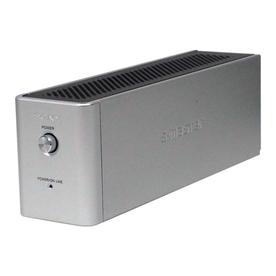
TA-SB500WR2 is the surround amplifier
section in DAV-HDX267W/HDX501W.
AUDIO POWER SPECIFICATIONS
POWER OUTPUT AND TOTAL HARMONIC
DISTORTION:
Amplifier section
Surround mode (reference) RMS output power
* Depending on the sound field setting and the source,
there may be no sound output.
Sony Corporation
9-887-591-01
Home Audio Division
2007C05-1
Published by Sony Techno Create Corporation
© 2007.03
TA-SB500WR2
SPECIFICATIONS
With 3 ohms loads, both
channels driven, from
120 Hz - 20,000 Hz; rated
60 watts per channel
minimum RMS power,
with no more than 0.7 %
total harmonic distortion
from 250 milli watts to
rated output.
SL/SR* : 100 W
(per channel at 3 ohms, 1
kHz, 10 % THD)
Power requirements:
120 V AC, 60 Hz
Power consumption
On: 40 W
Dimensions (approx.)
65
89
(2
/
3
5
5
8
(w/h/d)
65
89
(2
5
/
3
5
8
(w/h/d) incl. speaker cord
cover
Mass (approx.)
1.3 kg (2 lb 14 oz)
1.4 kg (3 lb 2 oz) incl.
speaker cord cover
Design and specifications are subject to change
without notice.
SURROUND AMPLIFIER
US Model
253 mm
/
10 inches)
8
345 mm
/
13
5
/
inches)
8
8
Advertisement
Table of Contents

Related Manuals for Sony TA-SB500WR2


Summary of Contents for Sony TA-SB500WR2
-
Page 1: Service Manual
SERVICE MANUAL Ver. 1.0 2007.03 TA-SB500WR2 is the surround amplifier section in DAV-HDX267W/HDX501W. AUDIO POWER SPECIFICATIONS POWER OUTPUT AND TOTAL HARMONIC DISTORTION: With 3 ohms loads, both channels driven, from 120 Hz - 20,000 Hz; rated 60 watts per channel minimum RMS power, with no more than 0.7 %... -
Page 2: Table Of Contents
COMPONENTS IDENTIFIED BY MARK 0 OR DOTTED LINE WITH MARK 0 ON THE SCHEMATIC DIAGRAMS AND IN THE PARTS LIST ARE CRITICAL TO SAFE OPERATION. REPLACE THESE COMPONENTS WITH SONY PARTS WHOSE PART NUMBERS APPEAR AS SHOWN IN THIS MANUAL OR IN SUPPLEMENTS PUBLISHED BY SONY. -
Page 3: General
POWER SPEAKER SURROUND L POWER ON-LINE SURROUND R A POWER (ON/OFF) B POWER/ON LINE indicator C DIR-R1 jack D SURROUND L SPEAKER jack E SURROUND R SPEAKER jack SECTION 1 GENERAL DIR-R1 TA-SB500WR2 This section is extracted from instruction manual. -
Page 4: Disassembly
TA-SB500WR2 This set can be disassembled in the order shown below. 2-1. DISASSEMBLY FLOW 2-2. WIRE COVER (Page 4) 2-3. TOP PANEL (Page 5) 2-4. SIDE PANEL, FRONT PANEL BLOCK (Page 5) 2-5. DIAT POWER BOARD (Page 6) 2-6. DIAT AMP BOARD (Page 6) Note: Follow the disassembly procedure in the numerical order given. -
Page 5: Top Panel
TA-SB500WR2 2-3. TOP PANEL 1 screw 4 top panel (BVTP3 3 eight claws 2-4. SIDE PANEL, FRONT PANEL BLOCK 3 side panel 1 six screws (2.6 7 connector (CN902) 5 two claws 8 front panel block 7 connector (CN901) 7 connector 4 two screws (2.6... -
Page 6: Diat Power Board
TA-SB500WR2 2-5. DIAT POWER BOARD 7 power shield 8 radiation sheet (DMB) 8 radiation sheet 2 two claws 4 two connectors (CN904) 9 fuse (F901) 5 four screws (2.6 × 6) 0 DIAT POWER board 6 A sheet power 1 two screws (2.6 ×... -
Page 7: Diagrams
X101 LEVEL /XSCEN 12.288MHz SHIFT OSCI SCMODE X102 8MHz D400 POWER/ON-LINE LED DRIVE Q104, 112 LED DRIVE Q103, 111 TA-SB500WR2 IC301 STREAM PROCESSOR 31 DATA OUTL1 30 BCK OUTL2 29 LRCK OUTR1 36 XFSIIN OUTR2 27 INIT IC114 XFSOIN IC107 SURROUND AMP CONTROLLER 49.152MHz... - Page 8 TA-SB500WR2 Note for Printed Wiring Boards and Schematic Diagrams Note on Printed Wiring Boards: Note on Schematic Diagram: X : parts extracted from the component side. All capacitors are in F unless otherwise noted. (p: pF) Y : parts extracted from the conductor side.
-
Page 9: Printed Wiring Board - Diat Amp Section (1/2)
3-2. PRINTED WIRING BOARD – DIAT AMP Section (1/2) – DIAT AMP BOARD (COMPONENT SIDE) Q107 R155 C166 FB109 TA-SB500WR2 : Uses unleaded solder. R950 IC904 C938 C937 R952 C954 C234 C222 C221 R183 R198 IC112 R196 C244 C207 C211... -
Page 10: Printed Wiring Boards - Diat Amp Section (2/2)
TA-SB500WR2 3-3. PRINTED WIRING BOARDS – DIAT AMP Section (2/2) – DIAT AMP BOARD (CONDUCTOR SIDE) CNP303 ET302 (CHASSIS) R278 C150 R139 R142 R126 R254 R254 R254 C115 C115 C115 R105 R105 R105 C151 C151 C151 R410 D301 C157 R143... -
Page 11: Schematic Diagram - Diat Amp Section (1/4)
FB101 L102 10uH C101 C104 C103 C108 C107 C102 C109 L103 FB102 10uH R103 TA-SB500WR2 See page 8 for Waveforms. See page 17 for IC Block Diagrams. C137 IC104 IC B/D +2.5V REGULATOR C138 IC104 TK11225CMCL-G R117 COUT VOUT C142... -
Page 12: Schematic Diagram - Diat Amp Section (2/4)
TA-SB500WR2 3-5. SCHEMATIC DIAGRAM – DIAT AMP Section (2/4) – DIAT LED BOARD D400 CNP400 SPR-54MVW POWER/ON-LINE GREEN GREEN VCC2 SCMODE XSCEN DIAT_SCLK DIAT AMP DIAT_SWDT BOARD (1/4) DTVALID(I) (Page 11) CSOD DIAT_SRDT INIT MOD 0_1 SCK2 RESET TA-SB500WR2 See page 8 for Waveforms. -
Page 13: Schematic Diagram - Diat Amp Section (3/4)
DAOUT/ROUT IC109 LEVEL SHIFT IC109 SN74LVC08APWR DIAT AMP BOARD (1/4) (Page 11) BCK/RCLK R168 LRCK/RCS VCC2 TA-SB500WR2 See page 8 for Waveforms. See page 17 for IC Block Diagrams. C220 C202 C219 1000p R201 IC B/D R194 XOVSS XFSOIN C206... -
Page 14: Schematic Diagram - Diat Amp Section (4/4)
TA-SB500WR2 3-7. SCHEMATIC DIAGRAM – DIAT AMP Section (4/4) – See page 17 for IC Block Diagrams. DIAT AMP BOARD (4/4) Q108 Q109 2SA1235TP-1EF 2SA1235TP-1EF Q108,109 OVER LOAD DETECT C166 R155 100k Q107 2SC3052EF-T1-LEF PROTECT DETECT C170 C177 0.033 IC B/D 11.2... -
Page 15: Printed Wiring Boards - Power Supply Section
R936 C942 CL011 C933 DIAT AMP JW13 BOARD CL012 CL008 CN301 CL009 CL006 (Page 10) CL010 CL007 R960 L903 TA-SB500WR2 : Uses unleaded solder. JW003 CL005 T901 C919 POWER D902 R906 C907 TH901 C908 R916 A002 D901 R915 IC901 CL001... -
Page 16: Schematic Diagram - Power Supply Section
TA-SB500WR2 3-9. SCHEMATIC DIAGRAM – POWER SUPPLY Section – DIAT SWITCH BOARD S901 CN901 CN902 POWER LIVE LIVE (AC IN) NUTRAL NUTRAL NUTRAL (CHASSIS) TA-SB500WR2 See page 17 for IC Block Diagrams. DIAT POWER BOARD F901 C904 D911 125V 10EDB60-TA2B5... -
Page 17: Ic Block Diagrams
20 21 22 23 24 58 57 56 53 52 51 50 49 CLOCK OUTPUT ERROR GENERATOR INTERFACE CORRECTOR CONTROLLER CLOCK SELECTOR 25 26 27 29 30 TA-SB500WR2 TEST4 TEST3 TEST2 TEST1 TEST0 OSCO VDDE OSCI SCMODE SCLK XSCEN SWDT SRDT CSOD... - Page 18 TA-SB500WR2 IC104 TK11225CMCL-G CONTROL CIRCUIT CONSTANT OVER HEAT & CURRENT OVER CURRENT SOURCE PROTECT BANDGAP REFERENCE IC110, 112 CXD9774M DVDD DREG DREG GND 1 PWM BP 2 RECEIVER TIMING GND 3 CONTROL DGND & PROTECTION RESET 4 DREG RTN 5...
- Page 19 VOUT CLOCK GENERATOR (SECONDARY) FILTER & LINER GAIN LOW CUT INTERPOLATOR CONTROL FILTER INIT/ SERIAL MUTE CONTROLLER TA-SB500WR2 CLOCK GENERATOR 36 XFSIIN (PRIMARY) 35 DVDD 34 TEST 33 BFVSS 32 BFVDD DATA SAMPLING RATE S g P CONVERTER LRCK 28 MCKSEL...
- Page 20 TA-SB500WR2 IC904 NJM2374AE (TE2) CS 1 LOGIC ES 2 CT 3 – – GND 4 VREF COMPARATOR ERROR AMP – DIAT POWER Board – IC901 STR-W6735N REGULATOR DELAY NC 2 S/GND 3 VCC 4 SS/OLP 5 FB 6 – –...
- Page 21 Serial interface enable signal output to the RF demodulator DIAT_SCLK Serial interface data clock signal output to the RF demodulator DIAT_SWDT Serial interface data write signal output to the RF demodulator DIAT_SRDT Serial interface data read signal input from the RF demodulator TA-SB500WR2 Description...
- Page 22 TA-SB500WR2 Pin No. Pin Name 54, 55 Not used Power supply terminal (+3.3V) MAIN_OFF Power off control signal output to the power control "H": power off V_CONT Voltage control PWM signal output terminal Not used DAMP_LATCH Latch control signal output to the stream processor...
-
Page 23: Exploded Views
2-149-272-11 HOLD, WIRE (A) 7-685-133-19 SCREW +P 2.6X6 TYPE2 NON-SLIT 7-682-548-09 SCREW +B 3X8 7-685-647-79 SCREW +BVTP 3X10 TYPE2 IT-3 TA-SB500WR2 The components identified by mark 0 or dotted line with mark 0 are critical for safety. Replace only with part number specified. -
Page 24: Diat Amp/Diat Power Boards Section
TA-SB500WR2 4-2. DIAT AMP/DIAT POWER BOARDS SECTION not supplied not supplied not supplied not supplied not supplied Ref. No. Part No. Description A-1227-906-A DIAT AMP BOARD, COMPLETE A-1221-192-A DIAT POWER BOARD, COMPLETE 3-703-244-00 BUSHING (2104), CORD 0 54 1-830-190-11 CORD, POWER... -
Page 25: Electrical Parts List
1-107-898-21 ELECT C200 1-164-346-11 CERAMIC CHIP C201 1-164-346-11 CERAMIC CHIP TA-SB500WR2 DIAT AMP The components identified by mark 0 or dotted line with mark 0 are critical for safety. Replace only with part number specified. When indicating parts by reference number, please include the board. - Page 26 TA-SB500WR2 DIAT AMP Ref. No. Part No. Description C202 1-126-947-11 ELECT 47uF C203 1-115-185-11 CERAMIC CHIP 0.033uF C204 1-164-156-11 CERAMIC CHIP 0.1uF C205 1-164-156-11 CERAMIC CHIP 0.1uF C206 1-164-156-11 CERAMIC CHIP 0.1uF C207 1-125-898-11 CERAMIC CHIP 0.22uF C208 1-125-898-11 CERAMIC CHIP 0.22uF...
- Page 27 R276 1-216-841-11 METAL CHIP 1/10W R278 1-216-841-11 METAL CHIP 1/10W 1/10W R283 1-216-841-11 METAL CHIP 1/10W R300 1-216-833-11 METAL CHIP R410 1-216-841-11 METAL CHIP TA-SB500WR2 DIAT AMP Description Remark 1/10W 1/10W 1/10W 100K 1/10W 100K 1/10W 100K 1/10W 100K 1/10W...
- Page 28 6-707-799-01 IC NJM1431AU (TE2) 0 L901 1-424-930-11 COIL, LINE FILTER L903 1-456-509-11 INDUCTOR 275V 0 PC901 6-600-438-01 IC TLP421F (D4-GR) 0 PC902 250V 8-749-018-06 IC TLP421F (D4-SONY) 250V 0 PC903 8-749-018-06 IC TLP421F (D4-SONY) 275V 630V 0 Q901 1.2KV 8-729-142-51 TRANSISTOR 0 Q902...
- Page 29 0 54 1-830-190-11 CORD, POWER 0 F901 1-533-453-12 FUSE, GLASS TUBE (DIA. 5) (5A/125V) Remark Ref. No. Part No. 1/4W 1/4W 1/4W 1/10W 0.5% 1/10W 1/10W 1/10W 0.5% 1/10W 1/10W 1/10W 1/10W 1/10W 1/10W TA-SB500WR2 DIAT POWER DIAT SWITCH Description Remark...
-
Page 30: Revision History
TA-SB500WR2 REVISION HISTORY Clicking the version allows you to jump to the revised page. Also, clicking the version at the upper right on the revised page allows you to jump to the next revised page. Ver. Date Description of Revision...