Table of Contents
Advertisement
Quick Links
Advertisement
Table of Contents

Related Manuals for Synology NAS HD6500


Summary of Contents for Synology NAS HD6500
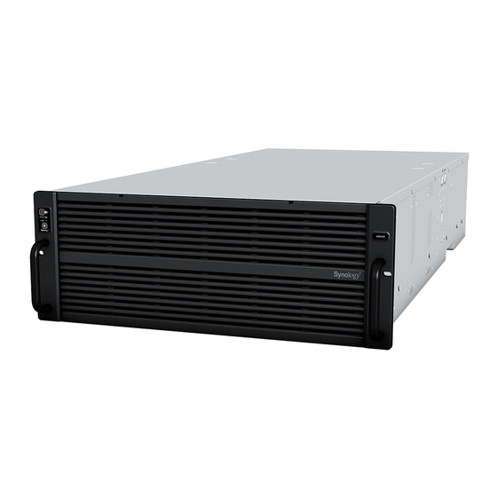
- Page 1 Synology NAS HD6500 Hardware Installation Guide...
-
Page 2: Table Of Contents
Install and Remove Rail Kits Expansion Unit Deployment and Topology Start up Your Synology NAS Chapter 3: System Maintenance Replace System Fan Replace Power Supply Unit (PSU) Chapter 4: Install DSM on Synology NAS Install DSM with Web Assistant Learn More Synology_HIG_HD6500_20210519... -
Page 3: Chapter 1: Before You Start
Chapter Before You Start Thank you for purchasing this Synology product! Before setting up your new Synology NAS, please check the package contents to verify that you have received the items below. Also, make sure to read the safety instructions carefully to avoid harming yourself or damaging your Synology NAS. -
Page 4: Synology Hd6500 At A Glance
Description 1. Press to power on your Synology NAS. POWER Button and 2. To power off your Synology NAS, press and hold until you hear Indicator a beep sound and the Power LED starts blinking. Displays the status of the system. For more information, see STATUS Indicator "System Modes and LED Indicators". - Page 5 SAS OUT Port Connect to Synology Expansion Unit here. (primary) SAS OUT Port Connect to Synology Expansion Unit here. (secondary) For more information about Synology Expansion Unit supported by your Synology NAS, please visit www.synology.com. 5 Chapter 1: Before You Start...
-
Page 6: System Modes And Led Indicators
System Modes and LED Indicators System Modes and Definitions There are 7 system modes in Synology NAS. The System modes and their definitions are as below: System mode Definition Synology NAS is powering on and performing hardware initialization, such as Powering on hardware reset or BIOS initialization. - Page 7 • Enter hibernation then wake up from hibernation: DSM is ready for use > Hibernation > DSM is ready for use • Shutdown Synology NAS: DSM is ready for use > Shutting down > Powered off • Power failure with UPS attached: DSM is ready for use >...
-
Page 8: Other Led Indicators
100 Mbps connected/No network Note: 1 Please try to restart your Synology NAS or re-insert the drives, then run the HDD/SSD manufacturer's diagnostic tool to check the health status of the drives. If you can sign in to DSM, please run the built-in S.M.A.R.T. -
Page 9: Hardware Specification
• Operating Temperature: 32 to 95˚F (0 to 35˚C) • Storage Temperature: -5 to 140˚F (-20 to 60˚C) • Relative Humidity: 5% to 95% RH Note: www.synology.com Model specifications are subject to change without notice. Please refer to for the latest information. 9 Chapter 1: Before You Start... -
Page 10: Spare Parts
PSU 1600W-RP Module_1 1600W RKS-03 Sliding rails solutions Optional Accessories With Synology accessories, you can customize your Synology NAS to fit different business environments without worrying about compatibility and stability. Visit www.synology.com/compatibility for more information. 10 Chapter 1: Before You Start... -
Page 11: Safety Instructions
Safety Instructions Keep away from direct sunlight and away from chemicals. Ensure a stable environment with no abrupt changes in temperature or humidity. Place the unit right side up at all times. Keep the unit away from liquids. Before cleaning, unplug the power cord. Do not use chemical or aerosol cleaners. Wipe with damp paper towels. -
Page 12: Chapter 2: Hardware Setup
• Rail mounting kit (please see the Optional Accessories section to find out the suitable rail kit for cabinet installation) Warning: We suggest mounting your Synology NAS on a cabinet before installing any drives since the heavy weight will increase the installation difficulty. Install Storage Drives Please follow the steps below for drive installation: 1 Open the front top cover. - Page 13 2 Pull the drive tray out by its handle as shown below. 3 Install 3.5" drives: Place the drive in the drive tray. 4 Insert the loaded drive tray into the empty drive bay. Note: Make sure that the drive tray is completely inserted. Otherwise, the drive might not function properly. 5 Push the handle inward to secure the drive tray.
-
Page 14: Install System Drives
7 Drives are numbered as shown below. Install System Drives Please follow the steps below for drive installation: 1 Unlock the drive tray. 14 Chapter 2: Hardware Setup... - Page 15 2 Open the drive tray. 1 Find the small button located on the drive tray handle. Press the button down, and the drive tray handle will pop out. 2 Pull the drive tray handle out as illustrated below. 3 Install 2.5" drives: Place the drive in the drive tray. Tighten screws into the four spots indicated below to secure the drive in place.
- Page 16 5 Lock the drive tray. 16 Chapter 2: Hardware Setup...
-
Page 17: Install Memory Modules
Install Memory Modules Optional Synology memory modules are designed to expand the memory of your Synology NAS. Follow the steps below to install, check, or remove a memory module on your Synology NAS. The following table shows the memory configuration for best practice:... - Page 18 To install the memory module 1 Shut down your HD6500. Disconnect all cables connected to your HD6500 to prevent any possible damage. 2 Open the rear top cover. 1 Remove the screw on the back of you HD6500. 2 Press the small buttons located on both sides of HD6500. 3 Slide open the rear cover, then lift it up and put it aside.
- Page 19 Control Panel > Info Center and check Total Physical Memory. If your Synology NAS does not recognize the memory or does not start up successfully, please make sure that the memory module is installed correctly. 19 Chapter 2: Hardware Setup...
- Page 20 To remove the memory module 1 Follow step 1 and 2 of the "To install the memory module" section to shut down your HD6500, disconnect the cables, and then remove the rear top cover as described above. 2 Cut the cable tie before removing the memory module. (The pre-installed memory module is cable-tied to prevent it from loosening during delivery.) Note: Avoid touching any components on the motherboard when cutting the cable tie.
-
Page 21: Install A Pcle Add-In Card
HD6500 provides four PCIe slot for optional add-in card expansion, allowing network interface card to be installed. To install network interface card 1 Follow step 1 and 2 of the "To install the memory module" section to shut down your Synology NAS, disconnect the cables and remove the top cover. - Page 22 4 Replace the rear top cover by following step 5 of the "To install the memory module" section. 5 Reconnect the cables that removed, then press the power button to turn on your Synology NAS. 22 Chapter 2: Hardware Setup...
-
Page 23: Install And Remove Rail Kits
Install and Remove Rail Kits Here we use RKS-03 as an example to illustrate how to install or remove the rail kits. For more information about the rail kit installation, please refer to the Quick Installation Guide that comes with the rail kit. To install the rail kit 1 Install the rail kit to the rack: 1 Attach the rear end of the rail kit assembly to the rack. - Page 24 2 Slide the front latch outward and insert the brackets into the rack holes. 3 Secure the rail screws and install cage nuts as illustrated. 24 Chapter 2: Hardware Setup...
- Page 25 2 Pull and hold the rear latch on the inner rail, as illustrated, and continue to pull out the inner rail from the assembly. 3 Attach the rail kit to the Synology NAS: 1 Align the fixing holes of the inner rail to the side of the chassis and slide backward to attach the inner rail.
- Page 26 4 With the help of another person, carefully align the inner rails to the outer rail assembly, and push the chassis towards the rack. 5 Pull the front latch of the inner rail as illustrated to unlock the inner rail, and continue pushing the chassis towards the rack.
- Page 27 6 Push the chassis into the end of rack and use the 4U screws to secure the chassis to the rack. To remove the rail kit 1 To remove the chassis from the rack, loosen and remove the screws from the rack. 27 Chapter 2: Hardware Setup...
- Page 28 2 Pull out the chassis from the rack. 3 Remove the chassis from the rack: 1 Slide outwards the rear latch of the inner rail to unlock the inner rail from the outer rail assembly. 2 With the help of another person, carefully remove the chassis from the rack. (You may remove all drives first to reduce the weight of the chassis.) 28 Chapter 2: Hardware Setup...
- Page 29 4 Remove the rail kit from the Synology NAS: 1 Loosen and remove the rail screws. 2 Pull out the middle latch as illustrated. 3 Slide forward to remove the inner rail. 5 Hold the rear latch on the inner rail, as illustrated, and continue to push back the inner rail to the assembly.
- Page 30 6 Loosen and remove the rail screws. 7 Pull out the brackets as illustrated, and slide the front latch backwards. 30 Chapter 2: Hardware Setup...
- Page 31 8 Remove the rail kit from the rack. 31 Chapter 2: Hardware Setup...
-
Page 32: Expansion Unit Deployment And Topology
HD6500 supports RX6022sas (60-bay) expansion units, providing seamless storage expansion when needed. HD6500 also supports multipath I/O for better stability and performance. This section will guide you through how to connect the expansion units to your Synology NAS. Please follow our instructions below strictly to avoid system error. - Page 33 2 For 1 HD6500 and 2 RX6022sas: HD6500 RX6022sas-1 RX6022sas-2 33 Chapter 2: Hardware Setup...
- Page 34 3 For 1 HD6500 and 3 RX6022sas: HD6500 RX6022sas-1 RX6022sas-2 RX6022sas-3 34 Chapter 2: Hardware Setup...
- Page 35 4 For 1 HD6500 and 4 RX6022sas: HD6500 RX6022sas-1 RX6022sas-2 RX6022sas-3 RX6022sas-4 35 Chapter 2: Hardware Setup...
- Page 36 • After you plug the expansion cable back in, please wait a few seconds for Synology NAS to recover data path and work properly. The time required is 60 sec for 1 connected expansion unit, 120 sec for 2 connected expansion unit, 180 sec for 3 connected expansion unit, or 240 sec for 4 connected expansion unit.
- Page 37 3 Press the power button on the front panel to power on your HD6500. The expansion unit ID of RX6022sas connected to HD6500 will be displayed in sequence on the back panel. HD6500 RX6022sas-1 RX6022sas-2 37 Chapter 2: Hardware Setup...
-
Page 38: Start Up Your Synology Nas
Connect at least one LAN cable to one of the LAN ports and the other end to your switch, router, or hub. 2 Press the power button to turn on your HD6500. Congratulations! Your Synology NAS is now online and detectable from a network computer. 38 Chapter 2: Hardware Setup... -
Page 39: Chapter 3: System Maintenance
Chapter System Maintenance Replace System Fan If a system fan malfunctions, please see the instructions below to open HD6500 and replace the malfunctioning fan. 1 Open the rear top cover. 1 Remove the screw on the back of you HD6500. 2 Press the small buttons located on both sides of HD6500. - Page 40 2 Fans are numbered as shown below: 3 Find the malfunctioning fan. Lift up the fan to remove it. 4 Prepare a new fan and slide it into HD6500. Make sure that the fan is aligned properly. 40 Chapter 3: System Maintenance...
-
Page 41: Replace Power Supply Unit (Psu)
Replace Power Supply Unit (PSU) If a PSU or its fan malfunctions, please follow the steps below to replace the malfunctioning PSU. 1 Unplug the power cord from the PSU that is to be replaced. Note: By pressing the Beep Off button, you can silence the long beep when it sounds. 2 Remove the malfunctioning PSU: 1 On the rear panel, push the lever of the PSU inward as shown. -
Page 42: Chapter 4: Install Dsm On Synology Nas
3 Enter either of the following into the address bar of your browser: find.synology.com synologynas:5000 4 Web Assistant will be launched in your web browser. It will search for and find the Synology NAS within the local network. The status of your HD6500 should be Installed. - Page 43 Section 5. License Limitations. The license set forth in Sections 1, 2 and 3 applies only to the extent that you have ordered and paid for the Product and states the entirety of your rights with respect to the Software. Synology reserves all rights not expressly granted to you in this EULA.
- Page 44 Arbitration Law and related enforcement rules of the country in which Synology Inc. was organized. In such cases, the arbitration will be limited solely to the dispute between you and Synology. The arbitration, or any portion of it, will not be consolidated with any other arbitration and will not be conducted on a class-wide or class action basis.
- Page 45 Section 3. Limited Warranty and Remedies 3.1 Limited Warranty. Subject to Section 3.2, Synology warrants to the Customer that each Product (a) will be free of material defects in workmanship and (b) under normal use will perform substantially in accordance with Synology's published specifications for the Product during the Warranty Period.
- Page 46 Section 4. Limitations of Liability 4.1 Force Majeure. Synology will not be liable for, or be considered to be in breach of or default under this Warranty on account of, any delay or failure to perform as required by this Warranty as a result of any cause or condition beyond its reasonable control (including, without limitation, any act or failure to act by Customer).
- Page 47 Arbitration Association, except as otherwise provided below. The arbitration will be conducted before a single arbitrator, and will be limited solely to the dispute between Customer and Synology. The arbitration, or any portion of it, will not be consolidated with any other arbitration and will not be conducted on a class-wide or class action basis. The arbitration shall be held in King County, Washington, U.S.A.
- Page 48 5.9 Entire Agreement. This Warranty constitutes the entire agreement, and supersedes any and all prior agreements, between Synology and Customer related to the subject matter hereof. No amendment, modification or waiver of any of the provisions of this Warranty will be valid unless set forth in a written instrument signed by the party to be bound thereby.
- Page 49 FCC Declaration of Conformity This device complies with Part 15 of the FCC Rules. Operation is subject to the following two conditions: (1) this device may not cause harmful interference, and (2) this device must accept any interference received, including interference that may cause undesired operation.
- Page 50 この装置は、クラス A 機器です。この装置を住宅環境で使用すると電波妨 害を引き起こすことがあります。この場合には使用者が適切な対策を講ずる よう要求されることがあります。 VCCI 一 A...