Table of Contents
Advertisement
Quick Links
Advertisement
Table of Contents

Related Manuals for Quickie Sunrise Q300M


Summary of Contents for Quickie Sunrise Q300M
- Page 1 000690713 Instructions for Use Q300M...
- Page 2 IF YOU ARE VISUALLY IMPAIRED, THIS DOCUMENT CAN BE VIEWED IN PDF FORMAT AT WWW.SUNRISEMEDICAL.CO.UK. Wheelchair Components We at SUNRISE MEDICAL have been awarded the ISO-9001 certificate, which affirms the quality of our products at every stage, from R & D to production.
- Page 3 When considering provision, please also note the body User Information size, weight including the distribution of body weight, the user’s physical and psychological constitution, the age Intended use power wheel wheelchairs: of the user, their living conditions, environment and the intended use.
-
Page 4: Table Of Contents
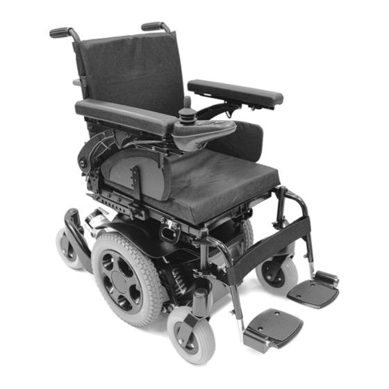
1.0 Your Wheelchair 8.0 Troubleshooting using the VR2 Hand Control 46 2.0 How to use this manual 9.0 Controller Mounts 2.1 Introduction 9.1 General warnings: 2.2 Guarantee 9.2 Attendant control: 3.0 Label Explantation / Word definitions 9.3 Parallel swing-away control: 9.4 Centre bar mount control (R-net) 3.1 Definitions of words used in this manual 9.5 Tray mount control (R-net) - Page 5 Q300M Armrest Cushion Legrest Controller Footplate Drive wheel Front castor Backrest Side Guard Rear castors Batteries Q300M Rev.1.0...
-
Page 6: Your Wheelchair
1.0 Your Wheelchair 2.0 How to use this manual 2.1 Introduction We at Sunrise Medical want you to get the best out of Please keep a note of your local service agent’s address your wheelchair . This Owner’s Manual will familiarise and telephone number in the space below. -
Page 7: Label Explantation / Word Definitions
3. For parts, which have been repaired or exchanged 3.0 Label Explantation / Word definitions within the scope of this warranty, we provide a warranty in accordance with these warranty conditions for the remaining warranty period for the product in 3.1 Definitions of words used in this manual accordance with point 1. -
Page 8: Label Explanations
3.2 Label explanations Lever position for the RIGHT-HAND freewheel mechanism. Lever position for the LEFT-HAND freewheel mechanism. IN DRIVE IN FREEWHEEL IN DRIVE IN FREEWHEEL Attached to Joystick WARNING – Do Not Touch - HOT WARNING – Do not drive your wheelchair on a slope with the backrest reclined and/or the seat lifted 140 Kg WARNING –... - Page 9 Labels and their descriptions Battery Label – Warning Instructions and Circuit Diagram Back Rest Recline Seat Lift The power Tilt and power Lift/Tilt modules are factory fitted for optimum stability and for conformance to strict standard Seat Tilt in Space requirements.
-
Page 10: General Safety Warning And User Tips
4.4 Routine service 4.0 General safety warning and user tips The recommended service interval is one year. (See 4.1 General warnings service history table, section 14, Fig.14.1). 4.5 Brake release WARNING! DANGER! • Always ensure that your wheelchair is switched off before attempting to transfer in or out. -
Page 11: Emc - Radio Transmitting Devices
4.6 EMC - Radio transmitting devices. 4.9 Batteries Your wheelchair is supplied as standard from Sunrise Medical with maintenance-free batteries. These only WARNING! require regular charging. Before charging, please read sections 10 and 12 in this manual. When operating two-way radio, walkie-talkies, C.B., amateur radio, public mobile radio and other powerful WARNING! transmitting devices the wheelchair should be brought to a... -
Page 12: Weight Limit
4.11 Weight limit 4.14 Wheelchair range The range of your wheelchair can be affected by many DANGER! factors such as user weight, terrain, ambient temperature, use of powered op tions and battery condition. • The user plus items carried should never exceed a total weight of 140 Kg. -
Page 13: Adverse Conditions
4.16 Adverse conditions 4.18 Transfer to and from the wheelchair Please be aware that when driving your wheelchair in WARNING! adverse conditions, e.g. on wet grass, mud, ice, snow or other slippery surfaces, you may experience a reduction • Sunrise Medical recommend that you consult your in the grip and traction of your wheelchair . -
Page 14: Use On A Slope
4.21 Use on a slope 4.21.1 Gradients: ascents Your wheelchair has been designed and tested to allow its use on slopes or gradients of up to 8° (14%). However, you WARNING! have the option of adjusting your seating position with a tilt or recline back rest or a combination of these options, •... -
Page 15: Creep Mode
4.23 Creep mode Furthermore different body proportions of a wheelchair user affect stability for example: WARNING! • Lower limb wasting or amputation, Obesity • Increased upper torso mass, Upper torso height Please ensure your backrest recline angle relative to floor level, which is a combination of the back recline itself and WARNING! the tilt angle, does not exceed 12°... -
Page 16: Rear View Mirror
4.26 Rear view mirror 4.29.1 Seat stay A seat stay is provided on your powered wheelchair to provide access for service and maintenance. (see section WARNING! 10 for additional information) To avoid injury to people around you please be aware that the mirror protrudes outside the space envelope of WARNING! the wheelchair and could cause injury to someone when... -
Page 17: Lap Belt (Standard Seat)
4.31 Lap belt (Standard Seat) WARNINGS! The lap belt kit. (Fig. 4.14). • Please show the utmost consideration for the other Fastening the lap strap: traffic on the road. Remember that the last thing a car Insert the 3 prong male buckle into the female buckle until or lorry driver expects to see is a wheelchair backing a click is heard (Fig. - Page 18 Fig. 4.16 DANGER • Always make sure that the lap strap is correctly secured and adjusted prior to use. • Too loose a strap could cause the user to slip down and cause serious injury. • Check lap strap and securing components at regular intervals for any signs of fray or damage.
-
Page 19: Vr2 Controller (Fig. 4.21)
4.32 VR2 Controller (Fig. 4.21) 5.0 Preparing your wheelchair for use 5.1 Handling the wheelchair Battery Level Indicator NOTE: To dismantle the wheelchair for transport or On/Off Button storage no tools are required. List of components when dismantled (components Speed Horn below are related to the maximum detachable parts and Indicator... -
Page 20: Re-Assembling
Fig. 5.6 Fig. 5.7 WARNINGS! • Make sure, when the wheelchair is stored or left in the car or anywhere else, the controller is switched off and the freewheel mechanisms are engaged, (in Drive). • If there is a need to lift the drive unit, use the rear castor arm and the drive wheel. -
Page 21: Drive Wheel Suspension Q300M
Please ensure the controller is switched off before you 5.5 Drive wheel suspension Q300M engage the release levers – Failure to do so will increase The Q300M has an effective and adjustable drive wheel the force needed to push the wheelchair. suspension system as a standard feature. -
Page 22: Control Joystick Unit Position
5.6 Control joystick unit position Fig.5.15 WARNING! • Make sure that the control system is mounted securely and that the joystick position is correct. • The hand or limb you use to operate the joystick should be supported, for example by the arm pad. •... -
Page 23: Armrests
5.8 Armrests 5.8.1 Armrests Flip Up, Standard Armrest. The armrests on both sides of the wheelchair can be flipped up to allow side transfer, (Fig. 5.18). • For side transfer flip the armrest all the way up until it goes into its mechanical stop. This frees your space for Fig. - Page 24 5.8.3. Standard and Recline Armrest Coarse Fig. 5.24 Adjustment. To achieve more than 25 mm Height Adjustment: 1. Use a 6.0 mm Allen key, (hexagon wrench), to loosen the rotation bolts on both armrests (B), (Fig.5.23). 2. Remove both armrest assemblies, (Fig.5.24). 3.
- Page 25 POSITION B POSITION A POSITION C STANDARD CONFIGURATION CHART BACKREST ANGLE ARMREST HEIGHT SETTING RING POSITION (Degrees) (mm) 305 - 254 252 - 229 305 - 254 252 - 229 305 - 267 279 - 229 305 - 229 305 - 229 248 - 229 305 - 254 260 - 229...
- Page 26 5.8.4 Standard Arm pad Position Adjustment To Adjust the Arm Pad Depth: 1. Using a 5.0 mm Allen Key, (Hexagon Wrench), loosen the two arm pad adjustment screws (A). 2. Slide the arm pad forward or backward as required. 3. Retighten both adjustment screws (A). Use 10 N/m or 88.5 in/lb of torque, (Fig.5.30, 5.31).
-
Page 27: Leg Rests
5.8.5 Arm Rest Replacement 5.9 Leg Rests Please refer to your appropriate armrest type. WARNING! To Remove The Standard Armrest: • Be aware of your environment to make sure you do not injure your legs when Leg Rests are extended. •... - Page 28 5.9.3 Leg rest removal Fig. 5.33 Fig. 5.34 To swing away the leg rest: • Depress the retaining catch and swing the leg rest out, (Fig.5.39). • Lift the leg rest up and off if removal is required, (Fig.5.40). To refit: •...
- Page 29 5.9.4 Standard Seat Hanger depth adjustment • Remove both sets of 5mm hanger depth adjustment bolts, (Fig.5.45). • Slide both hanger receivers to the desired location, (Fig.5.46, inset B). • Replace both sets of depth adjustment bolts, (Fig.5.47). • Use 20 N/m or 177 in/lb of torque. Fig.
- Page 30 5.9.5 Foot plates Fig.5.49 The foot plates may be flipped up to aid entry and exit from the wheelchair. WARNING! Do not use the foot plates to stand on as the full weight of your body may cause the wheelchair to tip forwards. This could result in injury and could damage the foot rests.
- Page 31 5.9.8 Powered elevating leg rest, (ELR, Fig.5.51) or Fig.5.51 Fig.5.52 articulating leg rest, (ALR, Fig.5.52). NOTE: Both left and right leg rests can also be operated simultaneously. To operate a powered ELR, or ALR leg rest: VR2 Control: The actuator buttons can operate any factory approved actuator.
-
Page 32: Seating
6.0 Seating 6.6 Standard Seat width adjustment 1. Remove the 5mm width adjustment bolts (A) and the 6.1 Firm seat board 4mm towel bar adjustment bolt (B), (Fig.6.5) . The firm seat board is designed to allow pressure relief 2. Move the left side seat rail, armrest and backrest cushions such as Jay to be used, (Fig.6.1). -
Page 33: Standard Seat Height Adjustment
6.7 Standard Seat height adjustment 6.8 Standard Seat Depth Adjustment 1. Remove the 5mm depth adjustment bolts from both WARNING! sides of the seat, (Fig.6.8). • Sunrise Medical strongly recommend that you contact your Sunrise Medical dealer to carry out this task. -
Page 34: Backrest Angle Adjustment
6.9 Backrest Angle Adjustment Fig. 6.12 1. Remove the 5mm backrest bracket index bolts (A) on both sides of the backrest. Loosen the 5mm backrest bracket pivot bolts (B) on both sides of the backrest. NOTE: The index bolt (A) may be in a different starting position than shown below in Fig.6.11. -
Page 35: Back Height Adjustment
6.10 Back Height Adjustment 4. Remove the 4mm towel bar bolts and the towel bar, (Fig.6.17). 1. Begin by removing the upholstery cover, (Fig.6.14). Fig. 6.17 Fig. 6.14 2. Loosen the upholstery straps. It is not necessary to remove NOTE: This step is not necessary in every case. If the the upholstery, (Fig.6.15). - Page 36 7. Replace the backpost adjustment screws. Use 10 N/m or 10. Retighten the upholstery straps, (Fig.6.23). 88.5 in/lb of torque, (Fig.6.20). Fig. 6.23 Fig. 6.20 11. Reattach the upholstery cover, (Fig.6.24). 8. If removed in Number 4, replace the towel bar and the towel bar bolts.
-
Page 37: Manual Adjustable Backrest (Standard Seat)
6.11 Manual adjustable backrest (Standard seat) 6.12 Manual setting of the seat angle. For depth adjustment see section 6.8. To set the seat angle, release the bolt fixing the “Banana” To recline the backrest angle: bracket between the seat interface module and the seat •... -
Page 38: Jay Backrests
6.13 JAY backrests Fig. 6.27 The standard backrest assembly will allow the fitting of a JAY backrest, which is available as an optional extra. 6.14 Headrest To fit the Standard headrest, fit the location bracket to the push handles, using the screws and nuts supplied, ensuring that they are fully tightened. -
Page 39: Powered Seating
6.15 Powered Seating To operate the Backrest Actuators: • Push the mode button to select actuator mode Powered adjustable backrest. • Operate the joystick left or right to select the actuator Powered seat Lift. required (actuator 1 or actuator 2). Selection is Powered Seat Tilt indicated via the lighting of the orange LED adjacent to the desired actuator number. - Page 40 6.15.2 Powered seat lift 6.15.3 Powered seat tilt The seat can lift up to 300 mm by operating it through The seat can be tilted by operating your control system. your control system. VR2 Control: To operate the powered tilt please follow the instructions WARNING! listed in section 6.11.2, but select the actuator button associated with the Tilt function.
-
Page 41: Control System
7.0 Control System 7.1 VR2 control system information 7.0 R-net control system information On/off button: The on/off button applies power to the control system electronics, which in turn supply power to the wheelchairs An alternative control system called R-net is available as motors. - Page 42 The horn button: Operating the control joystick: The horn will sound while this button is depressed. When engaging the main On/Off button, allow a few seconds prior to moving the joystick. This allows the Speed / Profile decrease button: system to self check. If you move the joystick too soon, This button decreases the maximum speed setting or, the battery level indicator display will not illuminate until if the control system is programmed for drive profile...
-
Page 43: Vr2-L, (Lights)
Lights and indicators: Charging and programming socket: The Q300M can be equipped with lights and indicators. Where lights are not factory fitted, they may be fitted WARNING! as an optional extra by an approved Sunrise Medical authorised dealer. This socket should only be used for programming and charging the wheelchair . -
Page 44: Vr2 Dual Control Unit
Actuator button and LEDs: Wheelchairs with one actuator: Depending on whether your wheelchair is fitted with one Depressing the actuator button once will enter actuator or two actuators the operation of this button will differ. adjustment mode. This will be indicated by the illumination of both actuator LED’s. - Page 45 Fig.7.1 JOYSTICK CONTROL PANEL CHARGER & PROGRAMMING SOCKET BATTERY GAUGE HAZARDS BUTTON ON-OFF BUTTON LIGHTS BUTTON HORN MAX. SPEED/ BUTTON PROFILE INDICATION ACTUATOR BUTTON SPEED/ PROFILE INCREASE BUTTON SPEED/PROFILE DECREASE BUTTON INDICATOR BUTTONS VR2 CONTROL PANEL LAYOUT VR2-L CONTROL PANEL LAYOUT JOYSTICK SPEED INDICATOR MAX.
-
Page 46: Troubleshooting Using The Vr2 Hand Control
8.0 Troubleshooting using the VR2 Hand Control Self help guide: (Fig.8.1, overleaf). If a system trip occurs you can find out what has happened by counting the number of bars on the battery WARNING! gauge that are flashing. Go to the number on the list which matches the number of Always consult your Sunrise Medical authorised dealer flashing bars and follow the instructions. - Page 47 Self Help Guide, (Fig.8.1). Fig.8.1 Fault code Possible cause The batteries need charging, or there is a bad connection to the battery. Check the connections to the battery. If the connections are good, try charging the batteries The left hand motor has a bad connection. Check the connections to the left hand motor. The left hand motor has a short circuit to a battery connection.
-
Page 48: Controller Mounts
9.0 Controller Mounts 9.3 Parallel swing-away control: 9.1 General warnings: WARNINGS! • Before adjusting the swing-away arm, switch off the WARNINGS! controller to avoid accidental displacement of the joystick which would cause unwanted movement of • Do not replace the joystick knob with any your wheelchair . -
Page 49: Centre Bar Mount Control (R-Net)
9.4 Centre bar mount control (R-net) 9.7 Forus control (R-net) WARNINGS! WARNING! • Ensure that you set the speed of the forus control to a • Make sure that the controller is fixed securely to the speed that you can comfortably follow. centre bar. -
Page 50: Emergency Stop Button
The forus push handle mechanism is centred with 9.9 Powered swing away arm (R-net) springs which will always bring it back to its centre position when the attendant’s hands are taken off the This option (Fig 10.4) is used to mount all chin controls or handles. -
Page 51: Speciality Controls
10.0 Speciality Controls Switching modes A variety of mode switches are available. These can be 10.1 Proximity head array divided into three types: internal, hardware mounted and external. WARNINGS • Internal: mode in left pad or right pad • The sensors used in this product will operate if moisture •... -
Page 52: Sip And Puff Control And Buddy Buttons
10.4 Sip and puff control and buddy buttons 10.6 Proportional chin control (Fig.10.7) The proportional chin control must be used in WARNINGS conjunction with the Omni Plus module. This is to give visual feedback for the selection of drive profiles and •... -
Page 53: Batteries And Charging
11.0 Batteries and charging Fig.11.1 WARNING! • Please read the owner’s manual supplied with the charger carefully. • Do not expose any part of the battery to direct heat (i.e. naked flame, gas fire). • When charging always place your charger on a hard surface in a room with good ventilation. -
Page 54: Safety Cut-Outs
11.2 Safety cut-outs 11.5 Battery care In the event of a short circuit there are several safety Below is set out a battery care plan for maintenance free systems built into your wheelchair to safeguard your batteries. This has been agreed between Sunrise electrical circuits. -
Page 55: General Charger Information
11.7 General charger information Fig.11.6 The external charger has been designed to charge two 12V sealed maintenance free batteries connected in series (= 24 V). 11.8 Charger safety features The chargers have features which prevent hazards or accidents occurring as a result of connecting batteries the wrong way round, overheating caused by fault conditions or attempting to charge wrong voltage batteries. -
Page 56: The Range Of Your Vehicle
11.11 The range of your vehicle 11.12 Common battery statements Most manufacturers of mobility products state the range Over the years, battery technology has moved forward of their vehicles either in the sales literature or within the but, unfortunately, some of the advice given on battery Owner’s Manual. -
Page 57: Battery Warranty
WARNINGS! 11.13 Battery warranty Battery warranties are subject to periods set by the • An extension cord should not be used unless manufacturers. However, most of these warranties are absolutely necessary. subject to a wear and tear clause, and if you genuinely •... -
Page 58: Transportation
12.0 Transportation WARNINGS! A wheelchair secured in a vehicle will not provide the • Alterations or substitutions must not be made to equivalent level of safety and security of a vehicle seating the wheelchairsecurement points or to structural system. Sunrise Medical recommends that the user and frame or components without consulting the transfers to the vehicle seating and uses the vehicle- manufacturer. -
Page 59: Occupant Restraint Instructions
Fig.12.3 WARNINGS! When the user being transported is a child, less than 22Kg mass and the vehicle involved has less than eight (8) seated passengers it is recommended that they be transferred to an UNCE Regulation 44 compliant child restraint system (CRS). This type of restraint system provides a more effective occupant restraint system than the conventional 3 point occupant restraint system and some CRS systems... -
Page 60: Crash Testing On The Q300M, All Models
12.3 Crash testing on the Q300M, all models. Fig.12.7 A representative Q300M wheelchair has been tested in accordance with the dynamic performance requirements specified in ISO 7176-19:2008: “Wheeled Mobility Devices for use in Motor Vehicles” using an Unwins four-point strap restraint system that conform to ISO 10542 or equivalent and was used in accordance with the WTORS manufacturer’s instructions. -
Page 61: Securing The Wheelchair Into The Vehicle
12.5 Securing the wheelchair into the vehicle 12.6 Hoisting the wheelchair: (Fig. 12.9 - 12.10 on previous page) (Fig.12.11) The Q300M can be hoisted, unoccupied, by means of four suitably rated lifting straps. WARNING! Connect the straps to the wheelchair using the four tie- down brackets. -
Page 62: Other Transport Requirements
We recommend you check with the following points with 12.9 Storage Spec removal of parts before travelling: the train operator: • There is suitable boarding access available to allow CAUTION! you to access the railway carriage. • There is suitable access to the intended “wheelchair ” Before you travel, please contact the appropriate carrier. -
Page 63: Maintenance And Cleaning
13.0 Maintenance and Cleaning 13.3 Drive wheel tyre repair CAUTION! WARNING! It is important that you follow the following cleaning and Wheel removal and tyre changing is a safety critical task. maintenance schedule in order to keep your wheelchair in If you do not feel confident in carrying out the following instructions, please contact your Sunrise Medical tip top condition. - Page 64 Fig.13.1 Fig.13.2 Fig.13.3 Fig.13.4 Fig.13.6 Fig.13.5 Fig.13.7 Fig.13.8 Q300M Rev.1.0...
-
Page 65: Removing The Castor Wheel
13.4 Removing the castor wheel Fig.13.9 WARNING! Castor wheel removal is a safety critical task. If you do not feel confident in carrying out the following instructions, please contact your Sunrise Medical Approved Dealer. • Use two 13mm spanners to undo axle bolt (fig 13.12) •... -
Page 66: Inspection Of The Upholstery/Seating
13.6 Inspection of the upholstery/seating Cleaning instructions for Comfort seating: Tears, dents, wearing or slackening of upholstery • Clean regularly to prevent build up or soiling. particularly near to metal could result in poor posture or • Clean with a damp soapy cloth and rinse well with lower levels of comfort and pressure relief. -
Page 67: Cleaning Controls
13.8 Cleaning controls CAUTION! Clean the control system and the joystick with a cloth dampened with diluted detergent. We recommend the use of Sunrise Medical authorised spare parts only. CAUTION! NOTE: Be advised that all lighting circuits are Be careful when cleaning the joystick. electronically protect ed. - Page 68 Q300M Fig.13.15 Parts in the battery box: • Plastic battery box cover for 2 x 12V batteries. • 2 x battery looms with fuse and ring terminals. • Battery link harness with grey connectors. Accessing the Batteries • Release the two handle screws under the front of the seat frame that connect the seat frame with the seat module interface, ( A-Fig.13.14).
-
Page 69: Controller Access
13.12 Controller access Fig.13.20 Accessing the Controller: • Release the two handle screws under the front of the seat frame that connect the seat frame with the seat module interface, ( A-Fig.13.20). • Flip the seat frame backwards and secure it with the safety bar, (B-Fig.13.21). -
Page 70: Recommended Maintenance Routines
13.15 Recommended maintenance routines CAUTION! (Fig13.35) Tools required: Please refer to the table below, (Fig.13.34), for any Battery charger, Tyre pump, Stiff brush, Petroleum jelly information about Torques. Cleaning cloth and dilute disinfectant. Fastener Matrix Torque Setting (Nm) WARNING! M3 Bolt / Stud If in any doubt about performing any maintenance on your M4 Bolt / Stud 2.5 - 3... -
Page 71: Performance Checks
13.16 Performance checks After performing any maintenance or repairs on the • With the seating in an elevated position, drive the wheelchair you must make sure that it is functioning wheelchair to make sure that the ‘creep’ mode works correctly before it is used. which will slow the wheelchair . -
Page 72: Wheels & Tires Maintenance
13.17 Wheels & tires maintenance To ensure that your wheelchair functions properly, it is essential that the tires are kept at the correct pressure. The correct tyre pressure is indicated on the side of the tyre. Tyres that are too soft will have a negative effect on the wheelchair’s performance. Moving the wheelchair will require more energy, making more demands on the batteries. -
Page 73: Specification Sheets (En 12184 & Iso 7176-15)
Moisture resistance: IPx4 West Midlands No restrictions on humidity and air pressure DY5 2LD Phone: 0845 605 66 88 www.SunriseMedical.co.uk Model: Quickie Q300M ISO 7176-15 Comments Overall length (with legrest) 1120 mm (1.12 m) With Uni type hangers Overall width powerbase... -
Page 74: Service History
15.0 Service History This section is designed to assist you in keeping a record of any service and repairs to your wheelchair . Should you decide to sell or exchange your vehicle in the future, this will prove most helpful to you. Your Service Agent will also benefit from a documented record and this manual should accompany the wheelchair when service or repair work is carried out. -
Page 75: Disposal
16.0 Disposal The symbols below mean that in accordance with local laws and regulations your product should be disposed of separately from household waste. When this product If the wheelchair has been supplied to you free of charge reaches the end of its life, take it to the local collection it may not belong to you. -
Page 76: Battery Wiring Diagram
17.0 Battery Wiring Diagram Fig.17.1 Fig.17.2 Charger Socket: Pin 1: Battery Positive Pin 2: Battery Negative Pin 3: Inhibit Fig.17.3 BATTERY CONNECTOR 100A YELLOW 100A BATTERY CONNECTOR BLACK BLACK AUXILIARY POWER CONNECTOR Q300M Rev.1.0... - Page 80 Website Addresses: = www.SunriseMedical.co.uk = www.SunriseMedical.de = www.sunrisemedical.fr = www.SunriseMedical.it = www.SunriseMedical.nl = www.SunriseMedical.es = www.SunriseMedical.pt = www.SunriseMedical.se = www.SunriseMedical.no = www.SunriseMedical.dk = www.SunriseMedical.ch = www.medicco.cz = www.Sunrise-Medical.pl = www.SunriseMedical.eu = www.sunrisemedical.com.au = www.SunriseMedical.com OM_Q300M_EU_EN_Rev.1.0_2018_02_20...