
Related Manuals for Samsung MW4592W


Summary of Contents for Samsung MW4592W
-
Page 1: Table Of Contents
MICROWAVE OVEN MW4592W / MW4593G SERVICE Manual CONTENTS MICROWAVE OVEN 1. Precaution 2. Specifications 3. Operating Instructions 4. Disassembly and Reassembly 5. Alignment and Adjustments 6. Troubleshooting 7. Exploded Views and Parts List 8. PCB Diagrams 9. Schematic Diagrams... - Page 2 (e) A Microwave leakage check to verify compliance with the Federal performance standard should be performed on each oven prior to release to the owner. Samsung Electronics...
-
Page 3: Precaution
10. Service technicians should remove their 16. Always connect a test instrument's ground watches while repairing an MWO. lead to the instrument chassis ground before connecting the positive lead; always remove the instrument's ground lead last. Samsung Electronics... - Page 4 PRECAUTION with the oven energized. DO NOT measure the voltage in the high voltage circuit Servicemen should remove their watches whenever including filament voltage of magnetron. working close to or replacing the magnetron. Samsung Electronics...
-
Page 5: Specifications
2. Specifications 2-1 Table of Specifications MODEL MW4592W / MW4593G ITEM TIMER 99 MINUTES, 99 SECONDS CONTROLS 10 POWER LEVELS, INCLUDING DEFROST POWER SOURCE 120V/60HZ, AC POWER CONSUMPTION MICROWAVE : 1,450W OUTPUT POWER 700 Watts OPERATING FREQUENCY 2,450MHz 8/32 26/32... -
Page 6: Operating Instructions
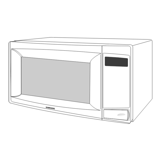
Pause / Canel Cancel Press to pause oven or correct a mistake. 3-2 Features & External Views Light Safety Interlock Holes Ventilation Holes Door Control Panel Door Latches Open Door Push Button Guide Roller Glass Tray 200mm 357mm 489mm 344mm Samsung Electronics... -
Page 7: Disassembly And Reassembly
HIGH VOLTAGE TRANSFORMER secondary and filament terminals. It is extremely dangerous to work on or near these circuits with the oven energized. DO NOT measure the voltage in the high voltage circuit including filament voltage of magnetron. Samsung Electronics... - Page 8 • Insertion depth of the thin metal plate should be 0.5mm or less. 4-3-3 Removal of Key Door & Spring Door "E" Remove pin hinge from Door "E" Detach spring from Door "E" and key door. Key Door Spring Samsung Electronics...
- Page 9 7. When replacing the drive motor, be sure to remount it in the correct position with the Drive Motor Cover Base Plate coupler. 8. Connect all the leads to the drive motor. 9. Screw the drive motor cover to the base plate with a screw driver. Samsung Electronics...
- Page 10 3. When installing new membrane key board, make sure that the surface of escutcheon base is cleaned sufficiently so that any problems (shorted contacts or uneven surface) can be avoided. Membrane Panel Samsung Electronics...
-
Page 11: Alignment And Adjustments
2. Isolate the magnetron from the circuit by disconnecting its leads. 3. A continuity check across the magnetron filament terminals should indicate one ohm or less. 4. A continuity check between each filament terminal and magnetron case should read open. Cooling Fins Samsung Electronics... - Page 12 Door Open Door Closed procedures. ∞ Primary switch 5. Confirm that the gap between the switch ∞ Monitor switch (COM-NC) housing and the switch actuator is no more than ∞ Door Sensing S/W 0.5mm when door is closed. Samsung Electronics...
- Page 13 NOTE 1: Variations or errors in the test procedure will cause a variance in the temperature rise. Additional power test should be made if temperature rise is marginal. NOTE 2: Output power in watts is computed by multiplying the temperature rise (step 5) by a factor of 91 times the of centigrade temperature. Samsung Electronics...
- Page 14 ; CENTRAL SERVICE CENTER 5-12-2 At least once a year have the microwave energy survey meter checked for accuracy by its manufacturer. Samsung Electronics...
-
Page 15: Troubleshooting
H.V.Transformer component test procedure and replace if it is H.V.Capacitor defective. H.V.Diode Magnetron 4. Open or loose wiring of power relay 5. Defective primary latch switch 6. Defective power relay or Ass'y PCB Replace PCB main. Samsung Electronics... - Page 16 Use plastic wrap or cover with a lid. Stir once or twice while cooking foods such as soup, cocoa, or milk. Noise from the turntable motor Noise may result from the motor. Replace turntable motor. when it starts to operate. Samsung Electronics...
-
Page 17: Exploded Views And Parts List
7. Exploded Views and Parts List 7-1 Exploded Views Samsung Electronics... - Page 18 PPS,7G,BRN,M97G45 DE61-40017A FOOT PP(A353),BLK,MW5630T DE80-10003B BASE-PLATE SGCC1-Z,T0.8,W340,L550,3RD-0.7 DE31-10154A MOTOR-DRIVE M2HJ49ZR02,ST-16,50/60HZ DE71-60450B COVER-MGT PP,T2,W110.5,L109,-,28G,3RD-0.7 DE93-30585A ASSY CONTROL-BOX MW4592W,-,3RD-W 0.7 S1 MW4592W DE93-30585B ASSY CONTROL-BOX 120V60HZ,MW4593G,GRAY MW4593G DE92-40220A ASSY DOOR MW4592W,-,3RDW 0.7 MW4592W DE92-40220B ASSY DOOR MW4593G,GRAY MW4593G DE39-20146A ASSY POWER CORD...
- Page 19 Exploded Views and Parts List 7-3 Door Parts List Ref. No. Parts No. Description Specification Q'ty Remarks DE64-40316A DOOR-A ABS,300g,WHT,389x261,MW749AW MW4592W DE64-40316C DOOR-A ABS,-,-,-,GRY,MW4593G MW4593G DE64-40006E DOOR-KEY POM(F20-02),-,-,12G,WHT,MW7896W,NO-TALK MW4592W DE64-40006A DOOR-KEY POM(TC3005),T2.0,12GR,BLK,CE94 MW4593G DE61-70033A SPRING-KEY ES,HSWR10,PI0.6,D6.0,L22.3,BLU DE67-20196A SCREEN-DOOR S1,-,-,-,-,3RD-0.7 DE92-50133A ASSY DOOR-E 3RD-0.7,COATING,WHT...
- Page 20 P/CORD DE60-10082H SCREW-A 2S-4X12,TOOTHED PCB-GND DE60-10098A SCREW-ASSY TAP TITE PH,TC,M4X8,SWRCH18A,ZPC2,GLD,W G-MOTOR DE60-10098A SCREW-ASSY TAP TITE PH,TC,M4X8,SWRCH18A,ZPC2,GLD,W DE60-10122A SCREW-TAP TH TAP,TH,2-4X8,FE,FN OUT-PA DE60-30016A NUT-FLANGE M4,MSWR10 F-MOTOR DE60-10098A SCREW-ASSY TAP TITE PH,TC,M4X8,SWRCH18A,ZPC2,GLD,W DE60-10012A SCREW-TAP TITE TH,+,3,M4,L10,SWR10,ZPC2,TOOTH DE60-10088A SCREW-TAP PH PH,M3,L8,FEFZY,PLAIN Samsung Electronics...
- Page 21 8. P.C.B Diagrams 8-1 P.C.B Diagrams Samsung Electronics...
- Page 22 2802-000161 RESONATOR-CERAMIC 4MHz,0.5%,TP,10.0x5.0x7.5mm XTL1 3711-000881 CONNECTOR-HEADER BOX,3P,1R,2.5mm,STRAIGHT,SN CN10 3711-000940 CONNECTOR-HEADER BOX,4P,1R,2.5mm,STRAIGHT,SN CN03 3711-004143 CONNECTOR-HEADER BOX,2P/3P,1R,5mm/2.5mm,STRAIGH CN07 DE13-20009A KA7533,DIP IC02 DE39-60001A WIRE-SO COPPER PI0.6,SN,T,52MM,TAPING_WIRE J01,J02,J04,J05,J10 DE39-60001A WIRE-SO COPPER PI0.6,SN,T,52MM,TAPING_WIRE J11,J12,J13,J14,J15 DE39-60001A WIRE-SO COPPER PI0.6,SN,T,52MM,TAPING_WIRE J16,J17 DE09-00031A IC-MCU TMP87CH21AF-2454,MW4592W,8BIT IC01 Samsung Electronics...
-
Page 23: Schematic Diagrams
DOOR IS OPENED ASSY PCB BOARD MAGNETRON BLK BLU HIGH VOLTAGE DIODE TO CHASSIS PRIMARY SWITCH HIGH VOLTAGE CAPACITOR DOOR SENSING SWITCH MONITOR SWITCH BOTTOM CENTER SYMBOL COLOR ORANGE HIGH VOLTAGE WHITE TRANSFORMER BLACK BLUE BLU RED POWER RELAY Samsung Electronics...