Advertisement
GENERAL DESCRIPTION
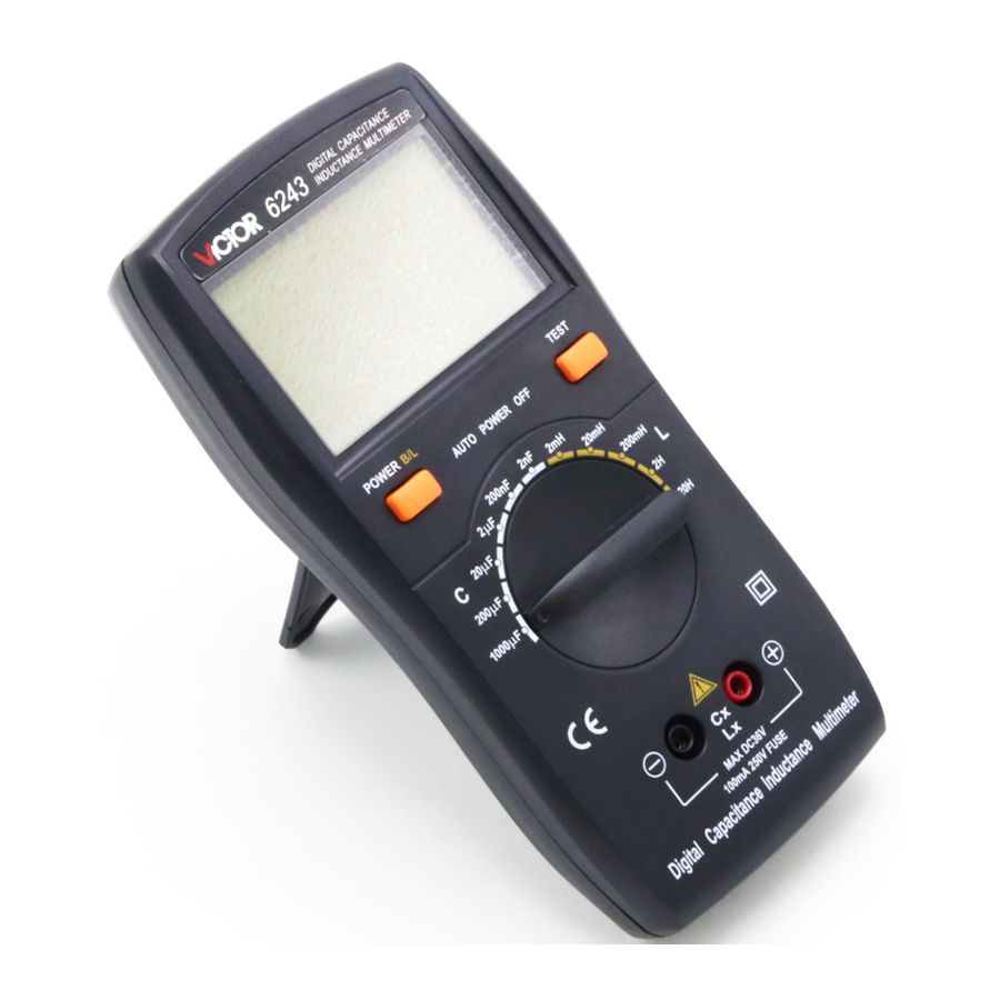
This 3 1/2 digital LC meter with high accuracy and unit symbol display function is driven by 9V battery. It has wide measurement ranges of inductance and capacitance. With light-weight and compact structure, it's widely applied in labs, production line, maintenance locations and schools. LSI-circuit provides high reliability and durability for this meter. It can accurately measure capacitance of cables, switches, PCB circuit, etc. It's also an ideal tool for testing transformer winding, inductive choke, and inductive components. In addition, the meter offers advanced features, such as capacitor self-discharge function. It can discharge the capacitor automatically, and protect the meter from the damage caused by voltage. But if the voltage carried by the capacitor is higher than 250V, please discharge the capacitor manually.
Please read this operation manual carefully before your operation!
CHARACTERISTICS
General characteristics
- Display: LCD Max display 1999.
- Inductance measurement: 1uH to 20H.
- Capacitance measurement: 1pF to 2000uF
- Calibration: Zero adjustment knob, can calibrate
![]() 20pF.
20pF. - Over range: display "1".
- Low battery indicator: "
![]() " symbol appears
" symbol appears - Sampling time: 0~5seconds
- Working conditions: 0℃ to 40℃, and relative humidity less than 80%
- Meter size: 185mm×93mm×35mm (length × width × height)
- Weight: about 290g (including battery)
- Power source: 9V (6F22 or equivalent). Battery life: 150 hours for alkaline battery, and 75 hours for carbon-zinc battery.
- Standard Accessories: test alligator clips (red & black), and manual.
 20pF.
20pF. " symbol appears
Technical data
Accuracy: ± (a% of reading+ digits) at 23 ± 5℃, relative humidity<75%.
Capacitance
| Range | Accuracy | Resolution |
| 2nF | ±(2.0%+5) | 1pF |
| 20nF | 10pF | |
| 200nF | 100pF | |
| 2μF | 1000pF | |
| 20μF | 0.01μF | |
| 2000μF | ±(5.0%+5) | 1μF |
Inductance
| Range | Accuracy | Resolution |
| 2mH | ±(2.0%+5) | 1uH |
| 20mH | 10uH | |
| 200mH | 100uH | |
| 2H | 1mH | |
| 20H | ±(5.0%+5) | 10mH |
OPERATION
Panel description

- LCD: display the measuring value, unit symbol and low battery indicator.
- POWER key: turn On/Off the meter.
- Zero adjustment knob/ "ADJ" knob: perform zero adjustment before measuring capacitance under 20nF.
- Rotary switch: select measuring range.
- Slot and jack: capacitance input terminal.
- Battery door.
Cautions before measurement
- To avoid false readings, which could lead to possible electric shock or personal injury, replace the battery as soon as the battery indicator "
![]() " appears.
" appears. - To avoid damage to the meter or to the equipment under test, disconnect circuit power source and discharge all high-voltage (higher than 250V) capacitors before measurement.
- Disconnect all the measuring components before switching the function knob.
- Capacitance measurement can't be used to check the quality of the capacitor. It may get a false reading when it measures the capacitance value of a resistor.
- Pay attention to the polarity if the capacitor is a polarized type. Use the red test clip to clip the capacitor's positive and the black test clip to clip the capacitor's negative when the capacitor has polarity.
- DO not connect the test terminal with voltage source, and do not measure the capacitor in circuit if there is high voltage. Even if it can get readings, it will cause the big error and damage the meter (when the circuit is not powered off or there exists voltage, or the capacitor isn't discharged completely).
- Do not short the test leads, otherwise it will cause dissipation of large current, and make over range display in all ranges.
- Zero adjustment will fail when SMD test clip's capacitance is bigger than 20pF.
- Inductance measurement can't be used to check the quality of inductor. It may get a false reading when it measures the inductance value of a resistor.
- Do not measure the capacitor in circuit. Even if it can get readings, it will cause the big error and damage the meter (when the circuit is not powered off or there exists voltage.)
Capacitance measurement
- Turn the rotary switch to a proper capacitance range;
- To obtain accurate measuring values, perform zero adjustment before measuring capacitance under 20nF. Slowly turn the "zero adjustment knob" to calibrate the display until the LCD shows "000". (Please perform the zero adjustment with test leads or SMD test clip inserted in);
- Insert the capacitor into the slot or clip the capacitor with test clip, the value will be displayed on LCD with the unit of the selected range. If LCD displays "1", it means over range. If there is "1" or "00" before the digit, choose a lower range to increase the resolution and accuracy.
Note:
- If the value of capacitor to be measured is unknown, choose the lowest range 2nF and increase the range step by step until a satisfactory reading is obtained and the over range symbol "1" is disappeared.
- If capacitor is breakdown, LCD will display over range symbol "1" in all ranges. If capacitor has small leakage, LCD will display over range symbol "1" or a big capacitance value which is much bigger than the normal value. If capacitor is open-circuit, LCD will display "0" at all ranges;
- When measuring the small (pF) capacitance, to minimize the effect of capacitance stored in the test clips, the test clips should be as short as possible and try to use the slot if it is possible. Keep the test clips close to the pins of capacitor under measuring, and then perform zero adjustment. Make sure the distance between test clips isn't change when you measure the capacitor, thus can get an accurate value.
- Some test leads may carry large capacitance, if it can't be calibrated by "ADJ" knob, you should remember the capacitance value, and then deduct it from your test results.
- Some capacitors especially the electrolytic capacitor will have large capacity. Don't be surprised if the test result is much bigger than the nominal value. Usually the test result is rarely smaller than the nominal value.
- To check the existence of leaky capacitor, switch the function knob to different capacitance ranges. If the test value has significant difference, it means there is a leaky capacitor. The difference increases proportionately with the capacitance of leaky capacitor.
Inductance measurement
- Turn the rotary switch to a proper inductance range;
- Insert the inductor into the slot or clip the inductor with test clip, the value will be displayed on LCD with the unit of the selected range. If LCD displays "1", it means over range. If there is "1" or "00" before the digit, choose a lower range to increase the resolution and accuracy.
Note:
- If the value of inductor to be measured is unknown, choose the lowest range 2mH and increase the range step by step until a satisfactory reading is obtained and the over range symbol "1" is disappeared.
- To avoid extra induction, use the test leads as short as possible when measuring small inductor.
- Inductance measurement can't be used to check the quality of inductor. It may get a false reading when it measures the inductance value of a resistor;
AUTO POWER OFF
When there is no measurement in 20 minutes, the meter will auto power off and enter dormancy mode. Press power button will exit the dormancy mode. It won't power off when LCD displays values bigger than 20% of the Max value at this range.
MAINTENANCE
The meter is a precise instrument. Random changes to the circuit are not allowed.
Note:
- Keep the meter away from water, dust and shock.
- Don't expose the meter under high temperature, high humidity, combustible, explosive and strong magnetic place.
- Wipe the case with a damp cloth and detergent. Do not use abrasives and alcohol to clean the meter.
- To avoid leakage damage, remove the battery if the meter will not be used for a long time.
- When
![]() symbol is displayed, please replace the battery according to the following steps:
symbol is displayed, please replace the battery according to the following steps:

- Follow the picture, and remove the holster at first.
- Unlock the battery door and remove the cover.
- Replace the old battery with the new one. For longer using life, it's better to use alkaline battery.
- Fix the battery door.
- Follow the picture to put on the holster
 symbol is displayed, please replace the battery according to the following steps:
- The specifications are subject to changes without prior notice.
- The content of this manual is regarded as correct. If users find out any mistakes or omissions, please kindly contact the manufacturer.
- The manufacturer will not be responsible for accidents and damage caused by improper operations. The functions described in this User Manual shall not be considered as the reason for any special usages.
Documents / ResourcesDownload manual
Here you can download full pdf version of manual, it may contain additional safety instructions, warranty information, FCC rules, etc.
Advertisement
Thank you! Your question has been received!


Need Assistance?
Do you have a question about the VC6243 that isn't answered in the manual? Leave your question here.