Table of Contents
Advertisement
Quick Links
IMPORTANT: Read safety rules and instructions carefully
Warning:
This unit is equipped with an internal combustion engine and should not be used on or near any unimproved forest-covered,
brush-covered or grass-covered land unless the engine's exhaust system is equipped with a spark arrester meeting applicable local or state
laws (if any). If a spark arrester is used, it should be maintained in effective working order by the operator. In the State of California the
above is required by law (Section 4442 of the California Public Resources Code). Other states may have similar laws. Federal laws apply
on federal lands. A spark arrester for the muffler is available through your nearest engine authorized service dealer or contact the service
department, P.O. Box 361131 Cleveland, Ohio 44136-0019.
PRINTED IN U.S.A.
Operator's Manual
MTD LLC, P.O. Box 361131 Cleveland, Ohio 44136-0019
Hydrostatic
Lawn Tractor
Model LT-1855H
(13AJ616G790)
FORM NO. 770-10314D.fm
(11/2003)
Advertisement
Table of Contents

Summary of Contents for White Outdoor LT-1855H
- Page 1 Operator’s Manual Hydrostatic Lawn Tractor Model LT-1855H (13AJ616G790) IMPORTANT: Read safety rules and instructions carefully Warning: This unit is equipped with an internal combustion engine and should not be used on or near any unimproved forest-covered, brush-covered or grass-covered land unless the engine’s exhaust system is equipped with a spark arrester meeting applicable local or state laws (if any).
-
Page 2: Customer Support
TABLE OF CONTENTS Content Page Content Page Customer Support Maintenance Important Safe Operation Practices Service Tractor Set-Up Attachments & Accessories Operation Illustrated Parts List Making Adjustments Warranty Back Cover FINDING MODEL NUMBER This Operator’s Manual is an important part of your new lawn tractor. It will help you assemble, prepare and maintain the unit for best performance. -
Page 3: Section 1: Important Safe Operation Practices
SECTION 1: IMPORTANT SAFE OPERATION PRACTICES WARNING: This symbol points out important safety instructions which, if not followed, could endanger the personal safety and/or property of yourself and others. Read and follow all instructions in this manual before attempting to operate this machine. Failure to comply with these instructions may result in personal injury. - Page 4 27. Use only accessories and attachments approved for this Do not tow heavy pull behind attachments (e.g. loaded machine by the machine manufacturer. Read, dump cart, lawn roller, etc.) on slopes greater than 5 understand and follow all instructions provided with the degrees.
-
Page 5: Your Responsibility
Never fill containers inside a vehicle or on a truck serviced professionally by your White Outdoor dealer. or trailer bed with a plastic liner. Always place Check brake operation frequently as it is subjected to containers on the ground away from your vehicle wear during normal operation. -
Page 6: Section 2: Slope Gauge
SECTION 2: SLOPE GAUGE... -
Page 7: Section 3: Tractor Set-Up
SECTION 3: TRACTOR SET-UP Attaching the Battery Cables NOTE: If these cables are already attached, ignore these steps and proceed to “Gas & Oil Fill-Up.” The positive battery terminal is marked Pos. IMPORTANT: (+). The negative battery terminal is marked Neg. (–). 1. -
Page 8: Section 4: Operation
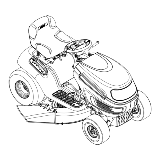
SECTION 4: OPERATION Know the Controls Read this owner’s manual and safety rules before operating your lawn mower. Compare figure below with your lawn tractor to learn about the loction and purpose of various controls and adjustments. Save this manual for future reference. - Page 9 Throttle Control Lever Choke Position The throttle control lever controls the speed of the engine. When set in a Fast given position, the throttle will maintain a uniform engine speed. Position Choke Control When pushed all the way forward, the throttle control lever also controls the choke.
- Page 10 Ignition Switch On/Lights Ignition switch is activated to start the engine. Insert key into the ignition switch and turn clockwise to the START position. Release the key into the ON position once engine has fired. Never leave a running machine unattended. Always WARNING: disengage PTO, move shift lever into neutral position, set parking brake, stop engine and remove key to prevent unintended starting.
-
Page 11: Safety Interlock Switches
PTO lever is in the “Blade Stop” position.If this AVOID SERIOUS INJURY OR DEATH system should ever malfunction, do not operate the tractor, immediately contact a White Outdoor dealer. • GO UP AND DOWN SLOPES, NOT ACROSS. • AVOID SUDDEN TURNS. -
Page 12: Starting The Engine
Starting the Engine NOTE: Refer to the TRACTOR SET-UP on page 7 manual for gasoline and oil fill-up instructions. IMPORTANT 1. Insert the tractor key into the ignition switch. 2. Place the PTO knob in the Blade Stop position. 3. Engage the tractor’s parking brake. 4. - Page 13 75 feet from the machine while it is in operation. Stop machine if anyone enters the area. This tractor is equipped with one of White Outdoor’s high quality cutting decks. The following information will be helpful when using the cutting deck with your tractor.
-
Page 14: Section 5: Making Adjustments
SECTION 5: MAKING ADJUSTMENTS Never attempt to make any adjustments while the engine is running, except where specified WARNING: in the operator’s manual.Disconnect spark plug wire(s) and ground against the engine before performing any adjustments, repairs or maintenance. Seat WARNING: Before operating this machine, make sure the seat is engaged in the seat stop, stand behind the machine and pull back on seat until fully engaged into stop. -
Page 15: Leveling The Deck
Front tire toe-in can be measured as follows: 1. Place the steering wheel in position for straight ahead travel. 2. In front of the axle, measure the distance horizontally from the inside of the left rim to the inside of the right rim. Note the distance. -
Page 16: Section 6: Maintaining Your Lawn Tractor
Refer to the Briggs & Stratton Engines Operator’s Manual for engine maintenance instructions. • Check engine oil level before each use as instructed in the White Outdoor Engines Operator’s Manual. Read and follow instructions carefully. Refer to this manual for details about type and grade of oil. - Page 17 Deck Wash System™ • Use the Deck Wash System™ to rinse grass clippings from the deck’s underside and prevent the buildup of corrosive chemicals. Complete the following steps after each mowing: Make certain the tractor’s discharge chute is IMPORTANT: directed away from your house, garage, parked cars, etc. 1.
-
Page 18: Section 7: Service
SECTION 7: SERVICE WARNING: Before servicing, repairing, or inspecting, always disengage PTO, move shift lever into neutral position, set parking brake, stop engine and remove key from tractor to prevent unintended starting. Tire Pressure Never exceed the maximum inflation pressure shown on the sidewall of the tire. IMPORTANT: •... -
Page 19: Cutting Deck Removal
2. Connect the other end of the positive (+) jumper cable to the positive (+) post of the good battery. 3. Connect one end of the negative (-) jumper cable to the negative (-) post of the good battery. 4. Connect the other end of the negative (-) cable to the engine block of the stalled tractor, away from the battery, and stand back. - Page 20 1. Remove the deck from beneath the tractor, then gently flip the deck over to expose its underside. Hex Flange Nut 2. Place a block of wood between the center deck Wood Block housing baffle and the cutting blade to act as a stabilizer.
- Page 21 WARNING: Shut tractor engine off, remove ignition key, disconnect the spark plug wire(s) and ground against the engine before proceeding with job. The V-belts on your tractor are specially designed to engage and disengage safely. A substitute (non- IMPORTANT: OEM) V-belt can be dangerous by not disengaging completely. For a proper working machine, use factory approved belts.
-
Page 22: Hydrostatic Transmission
Extinguish cigarettes, cigars, pipes, and other sources of ignition prior to draining fuel. • Follow instructions in the Seasonal Storage section of the White Outdoor Engine Operator’s Manual for proper engine care prior to storing your tractor. •... -
Page 23: Attachments & Accessories
Attachments & Accessories The following attachments and accessories are available for your lawn tractor. See your local White Outdoor dealer for information regarding price and availability. MODEL DESCRIPTION 190-116 42-inch Deck Mulch Kit 190-601 Twin Bagger Grass Collector 190-603 Grille Guard (mounts on front of tractor) 190-604 Yard-Mate™... -
Page 24: Section 9: Parts List For Lt-1855H
SECTION 9: PARTS LIST FOR LT-1855H (Part of #26) 1 19... - Page 25 Model LT-1855H Ref. Part Ref. Part Description Description 710-3015 Hex Cap Screw, 1/4-20 x .75 631-04035A Dash Panel, 4-style w/ Cargo Net 710-0599 Self-tapping Screw, 1/4-20 x .5 731-04214 Parking Brake Button 712-0324 Lock Nut, 1/4-20 731-1857 Throttle Control Lever 710-0895 Self-tapping Screw, 1/4-15 x .75...
- Page 26 Model LT-1855H 57 58...
- Page 27 Model LT-1855H Ref. Part Description Ref. Part Description 747-1130B Deck Stabilizer Rod 736-3078 Flat Washer, .349 x 1.0 x .063 683-0197B Lift Shaft Assembly 783-0677 Lift Adjustment Bracket 711-0332 Clevis Pin, .5 x .78 783-04333 Fender 712-3083 Lock Nut, 1/2-13...
- Page 28 Model LT-1855H...
- Page 29 Model LT-1855H Ref. Part Ref. Part Description Description 719-0525C Pivot Bar: Axle 683-04004 RH Axle Assembly, .750 Diameter 710-0604A Self-tapping Screw, 16-18 x .625 719-0525C Steel Pivot Bar 783-0726B RH Pivot Support Bracket 712-0130 Lock Nut, 3/8-16 783-0727A LH Pivot Support Bracket...
- Page 30 Model LT-1855H...
- Page 31 Model LT-1855H Ref. Part Ref. Part Description Description 17840 Mounting Bracket: Transaxle 747-1149 Bypass Rod 618-0319 Transmission: Hydrostatic 747-1151 Control Rod 629-0949A Harness Assembly 748-0334 Spacer: Transaxle 710-0227 AB Screw #8-18 x 0.5 750-0535 Spacer 710-0344 Hex Bolt 3/8-16 x 1.5...
- Page 32 Model LT-1855H 35 36...
- Page 33 Model LT-1855H Ref. Part Ref. Part Description Description 647-0064 PTO Engage Lever Assembly 736-0407 Bell Washer, .45 x 1.0 x .062 683-0450 PTO Engage Plate Assembly 712-0459 Flange Lock Nut, 7/16-20 710-0276 Carriage Screw, 5/16-18 x 1.00 783-04329 Seat Bracket: Frame 710-0520 Hex Cap Screw 3/8-16 x 1.5...
- Page 34 Model LT-1855H Ref. Part No. Description 710-0227 AB Screw #8-18 x 0.5 710-0599 TT Screw 1/4-20 x 0.5 710-0726 AB Screw 5/16-12 x 0.5 710-1237 T screw #10-32 x 0.625 710-1314A Socket Head Screw 5/16-18 x .750 710-1315 TT Screw 3/8-16 x 1.25...
- Page 35 Model LT-1855H SYSTEMS INDICATOR MONITOR YEL/WHT ORG/BLK...
- Page 36 Model LT-1855H...
- Page 37 Model LT-1855H Ref. Part Description 711-04069 Grass Catcher Pin, 1/4-20 618-0574 Spindle Assembly, 5.75 Dia. w/ Fitting 756-0980 Pulley Only 683-04051A 42-inch Deck Shell 683-0254 Deck Adjustment Bracket w/ Weld Nut 736-0140 Flat Washer, .385 x .62 x .063 710-0520 Hex Cap Screw, 1/4-20 x 1.5...
-
Page 38: Your Notes
YOUR NOTES Date Comment... - Page 39 YOUR NOTES Date Comment...
- Page 40 MANUFACTURER’S LIMITED WARRANTY FOR: The limited warranty set forth below is given by MTD LLC with MTD does not extend any warranty for products sold or respect to new merchandise purchased and used in the exported outside of the United States, its possessions United States, its possessions and territories.