Table of Contents
Advertisement
Quick Links
Safe Operation Practices • Set-Up • Operation • Maintenance • Service • Troubleshooting • Warranty
O
'
M
peratOr
s
anual
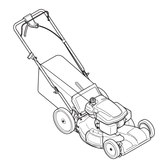
Self Propelled Mower — Model Series VB20
WARNING
READ AND FOLLOW ALL SAFETY RULES AND INSTRUCTIONS IN THIS MANUAL
BEFORE ATTEMPTING TO OPERATE THIS MACHINE.
FAILURE TO COMPLY WITH THESE INSTRUCTIONS MAY RESULT IN PERSONAL INJURY.
MTD LLC, P.O. BOX 361131 CLEVELAND, OHIO 44136-0019
Printed In USA
Form No. 769-07347
(December 23, 2011)
Advertisement
Table of Contents

Related Manuals for MTD 12AGB2JA004


Summary of Contents for MTD 12AGB2JA004
- Page 1 READ AND FOLLOW ALL SAFETY RULES AND INSTRUCTIONS IN THIS MANUAL BEFORE ATTEMPTING TO OPERATE THIS MACHINE. FAILURE TO COMPLY WITH THESE INSTRUCTIONS MAY RESULT IN PERSONAL INJURY. MTD LLC, P.O. BOX 361131 CLEVELAND, OHIO 44136-0019 Printed In USA Form No. 769-07347...
-
Page 2: Table Of Contents
Visit us on the web at www.mtdproducts..com See How-to Maintenance and Parts Installation Videos at www.mtdparts.com/KnowledgeCenter ◊ Call a Customer Support Representative at (800) 800-7310 or (330) 220-4683 ◊ Write to MTD LLC • P.O. Box 361131 • Cleveland, OH • 44136-0019... -
Page 3: Safe Operation Practices
Important Safe Operation Practices WARNING: This symbol points out important safety instructions which, if not followed, could endanger the personal safety and/or property of yourself and others. Read and follow all instructions in this manual before attempting to operate this machine. Failure to comply with these instructions may result in personal injury. - Page 4 A missing or damaged discharge cover can cause blade When starting engine, pull cord slowly until resistance contact or thrown object injuries. is felt, then pull rapidly. Rapid retraction of starter cord (kickback) will pull hand and arm toward engine faster than Many injuries occur as a result of the mower being pulled you can let go.
- Page 5 Service Check the blade and engine mounting bolts at frequent intervals for proper tightness. Also, visually inspect blade Safe Handling Of Gasoline: for damage (e.g., bent, cracked, worn) Replace blade with the original equipment manufacture’s (O.E.M.) blade only, To avoid personal injury or property damage use extreme listed in this manual.
- Page 6 Notice Regarding Emissions Spark Arrestor Engines which are certified to comply with California and federal WARNING: This machine is equipped with an EPA emission regulations for SORE (Small Off Road Equipment) internal combustion engine and should not be used are certified to operate on regular unleaded gasoline, and on or near any unimproved forest-covered, brush may include the following emission control systems: Engine covered or grass-covered land unless the engine’s...
- Page 7 Safety Symbols This page depicts and describes safety symbols that may appear on this product. Read, understand, and follow all instructions on the machine before attempting to assemble and operate. Symbol Description READ THE OPERATOR’S MANUAL(S) Read, understand, and follow all instructions in the manual(s) before attempting to assemble and operate DANGER —...
- Page 8 2 — i ection mportant peration racticeS...
-
Page 9: Assembly & Set-Up
Assembly & Set-Up Contents of Carton • One Lawn Mower • One Grass Catcher • One Bottle of Oil • One Lawn Mower Operator’s Manual • One Engine Operator’s Manual • One Side Discharge Chute Assembly While stabilizing mower so it doesn’t move, pivot upper handle up as shown in Fig. - Page 10 Remove the T-bolts from the handle brackets as shown in Fig. 3-3. Figure 3-5 The rope guide is attached to the right side of the upper handle. Loosen the wing knob which secures the rope Figure 3-3 guide. See Fig. 3-6. Hold blade control against upper handle.
- Page 11 Side Discharge Chute Slip plastic channel of grass bag over hooks on the frame. See Fig. 3-7. Your mower is shipped as a mulcher. To convert to side discharge, make sure grass catcher is off of the unit and rear discharge door is closed.
- Page 12 Move lever to desired position for a change in cutting Position the handle in one of the three positions that is height. See Fig. 3-10. most comfortable. See Fig. 3-11 inset. Secure into position with wing nuts and carriage bolts removed earlier.
-
Page 13: Controls & Features
Controls and Features Blade Control Drive Control Electric Start Ignition Switch Recoil Starter Side Discharge Chute Deck Wash Cutting Height Adjustment Lever Cutting Height Adjustment Lever Figure 4-1 Blade Control Deck Wash (If Equipped) The blade control is attached to the upper handle of the mower. Your mower’s deck is equipped with a water port on its surface Depress and squeeze it against the upper handle to operate the as part of its deck wash system. -
Page 14: Operation
Operation Starting Engine Using as Mulcher WARNING: For mulching grass, remove the grass catcher and allow the rear Be sure no one other than the operator discharge door to close the rear opening of mower. For effective is standing near the lawn mower while starting mulching, do not cut wet grass. -
Page 15: Maintenance & Adjustment
Maintenance & Adjustments Maintenance The transmission is pre-lubricated and sealed at the factory and does not require lubrication. General Recommendations Follow the accompanying engine manual for lubrication schedule and instruction for engine lubrication. • Always observe safety rules when performing any maintenance. - Page 16 Deck Wash (If Equipped) Engine Care Your mower’s deck may be equipped with a water port on its A list of key engine maintenance jobs required for good surface as part of its deck wash system. performance by the mower is given below. Follow the accompanying engine manual for a detailed list and instructions.
-
Page 17: Service
Service Blade Care WARNING: An unbalanced blade will cause excessive vibration when rotating at high speeds. It WARNING: When removing the cutting blade for may cause damage to mower and could break sharpening or replacement, protect your hands with causing personal injury. a pair of heavy gloves or use a heavy rag to hold the Lubricate the engine crankshaft and the inner surface of blade. - Page 18 Replacing Battery (If Equipped) Charging Battery (If Equipped) WARNING: WARNING: Batteries contain sulfuric acid which The battery contains corrosive fluid may cause burns. Do not short circuit or mutilate and toxic material; handle with care and keep away batteries in any way. Do not put batteries in fire as from children.
- Page 19 Replacing Fuse (If Equipped) Off-Season Storage The electric starter circuit and battery are protected by a 40 The following steps should be taken to prepare your lawn mower ampere fuse. If the fuse burns out, the electric starter will not for storage.
-
Page 20: Troubleshooting
Troubleshooting Problem Cause Remedy Engine Fails to start 1. Blade control disengaged. 1. Engage blade control. 2. Spark plug boot disconnected. 2. Connect wire to spark boot. 3. Fuel tank empty or stale fuel. 3. Fill tank with clean, fresh gasoline. 4. - Page 21 Problem Cause Remedy Uneven cut 1. Wheels not positioned correctly. 1. Place front and rear wheels in same height position. 2. Dull blade. 2. Sharpen or replace blade. Mower will not self propel 1. Belt not installed properly. 1. Check belt for proper pulley installation and movement.
-
Page 22: Replacement Parts & Accessories
Replacement Parts & Accessories Component Part Number and Description 951-10292 Spark Plug (MTD) BS-799876 Spark Plug (Briggs & Stratton) 951-10298 Air Cleaner Kit (MTD) BS-491588S Air Filter Cartridge (Briggs & Stratton) BS-493537S (Briggs & Stratton) † Pre-Cleaner 951-10300 Fuel Cap Assembly (MTD) BS-796577 Fuel Tank Cap (Briggs &... - Page 23 Component Part Number and Description 731-07486 Discharge Chute 942-0741A Mulching Blade 942-04380 Xtreme Mulching Blade 764-04082A Grass Bag 954-04260 Belt 725-04329 Battery Charger † 725-04903 Battery † 925-0201 † 490-850-0005 Blade Removal Tool Accessories 490-850-0008 Oil Siphon † If Equipped (800) 800-7310 or (330) 220-4683 Phone to order replacement parts or a complete Parts Manual (have your full model number and...
-
Page 24: Warranty
MANUFACTURER’S LIMITED WARRANTY FOR The limited warranty set forth below is given by MTD LLC with c. Routine maintenance items such as lubricants, filters, blade respect to new merchandise purchased and used in the United States sharpening, tune-ups, brake adjustments, clutch adjustments,...