Table of Contents
Advertisement
Quick Links
Advertisement
Table of Contents

Related Manuals for MTD 136


Summary of Contents for MTD 136
- Page 1 Electric Lawn Mower 13” Rear Bagger Model 136 IMPORTANT: READ SAFETY RULES AND INSTRUCTIONS CAREFULLY This symbol on the product’s nameplate means it is listed by ® UNDERWRITERS LABORATORIES INC. MTD LLC P.O. BOX 361131 CLEVELAND, OHIO 44136-9722 FORM NO. 770-10502B- (9/2002)
-
Page 2: Table Of Contents
For future reference, please copy the model number and the serial number of the equipment in the space below. (Model Number) (Serial Number) Copy the model number here: MTD LLC Copy the serial number here: P. O. BOX 361131 CLEVELAND,OH 44136 330-220-4683 www.mtdproducts.com... -
Page 3: Important Safe Operation Practices
SECTION 1: IMPORTANT SAFE OPERATION PRACTICES READ ALL INSTRUCTIONS! WARNING: This symbol points out important safety instructions, which if not followed, could endanger the per- sonal safety and/or property of yourself and others. Read and follow all instructions in this manual before attempting to operate this machine. - Page 4 16. Home circuit – This mower should be operated on a 15 31. Only use parts and accessories made for this machine by AMP circuit. If you experience difficulty in starting with a the manufacturer. Failure to do so can result in personal standard 15 AMP fuse or circuit breaker, contact your injury.
- Page 5 Service 10. Never tamper with safety devices. Check their proper operation regularly. When servicing use only identical replacement parts 11. After striking a foreign object, stop the motor and listed in this manual. “Use of parts which do not meet the disconnect the power cord.
-
Page 6: Slope Gauge
SECTION 2: SLOPE GAUGE Use this page as a guide to determine slopes where you may not operate safely. Do not operate your lawn mower on such slopes. -
Page 7: Assembling Your Lawn Mower
SECTION 3: ASSEMBLING YOUR LAWN MOWER Loose Parts in Carton • Repeat this step for all wheels, being certain that all four wheels are in the same height position for an • Grass Catcher Assembly. even cut. Refer to Figure 1 for cutting height •... - Page 8 • Align the holes in the lower handle with those of the upper handle and insert the hex bolts through both Cord Restraint holes. • On the left side, install the lock washer and hex nut Guide Rod and tighten finger tight. Upper Handle •...
- Page 9 Attaching The Grass Catcher • Insert the six clips on the underside of the bagger cover into the corresponding attaching slots in the • Lift the rear discharge door on the back of the grass bag. mower. Refer to Figure 6. •...
-
Page 10: Know Your Lawn Mower
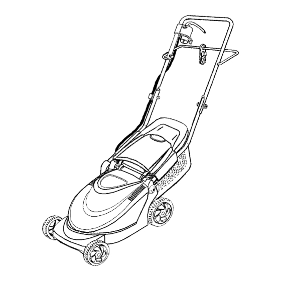
SECTION 4: KNOW YOUR LAWN MOWER Motor/Blade Control Assembly Guide Rod Cord Restraint Cord Insulator Lower Handle Rear Discharge Door Grass Catcher Electric Motor Rear Trailing Shield Figure 7 Read this operator’s manual and safety rules before the rear of the mower. operating your lawn mower. -
Page 11: Operating Your Lawn Mower
SECTION 5: OPERATING YOUR LAWN MOWER Cord Connection Connecting to the Electric Power Source WARNING: Extension Cord Selection This mower should be operated on a 15 AMP circuit. If you experience difficulty in Listed below are the lengths of extension cord and starting with a standard 15 AMP fuse or circuit corresponding acceptable cord ratings. -
Page 12: Making Adjustments
Stopping the Motor and Blade T = Obstacles WARNING: The blade continues to rotate for a few seconds after the motor is shut off. If the motor does not come to a stop when the motor/blade control handle is released, contact an authorized service dealer. -
Page 13: Maintaining Your Lawn Mower
• Remove a wheel assembly and reinstall it in a • If this occurs, unplug the mower, wait different position in order to achieve a higher or approximately five minutes, then depress the reset lower position. Refer to the Assembly section also. button. -
Page 14: Off-Season Storage
Sharpening the Blade • Reinstall the blade as described earlier in this section making certain to torque the cutting blade to To sharpen the blade, first remove the blade as outlined specifications. in the previous section. DO NOT attempt to sharpen the blade while it is attached to the mower. -
Page 15: Troubleshooting
SECTION 9: TROUBLE SHOOTING GUIDE Trouble Possible Cause(s) Corrective Action Mower not starting. Cord disconnected from the motor/ Reconnect the cord keeping the cord restraint close blade control. to the motor/blade control. Motor/blade control switch defective. Replace motor/blade control switch. Extension cord not connected to a Connect the extension cord to a 110-120 volt 60 source of power. -
Page 16: Parts List
SECTION 10: PARTS LIST 23 24... - Page 17 REF. PART NO. DESCRIPTION 749-1042A Upper Handle 749-1312 Lower Handle 720-0369 Handle Plug 710-1718 Handle Bolt 736-0649 Lock Washer 712-0690 Hex Nut 710-1757 Screw 725-1941 Motor / Blade Control Switch 731-2427 Cord Insulator 731-2421-0638 Mower Housing (Incl. Ref# 39-41) 731-2088A-0637 Electric Motor Cover 731-2224 Air Guide Pot...
- Page 18 NOTES...
- Page 19 NOTES...
- Page 20 MANUFACTURER’S LIMITED WARRANTY FOR: The limited warranty set forth below is given by MTD LLC with MTD LLC does not extend any warranty for products respect to new merchandise purchased and used in the sold or exported outside of the United States, its United States, its possessions and territories.