Scotsman DCE33 User Manual
Residential ice machine
Hide thumbs
Also See for DCE33:
- Technical training manual (45 pages) ,
- User manual (25 pages) ,
- Service bulletin (4 pages)
Table of Contents
Advertisement
Advertisement
Table of Contents

Related Manuals for Scotsman DCE33


Summary of Contents for Scotsman DCE33
- Page 1 User's Manual for Residential Ice Machine DCE33 Model...
-
Page 2: Table Of Contents
DCE33 INTRODUCTION This service manual is intended as a resource for The Scotsman DCE33 is a restaurant type ice people installing, using, and servicing the DCE33. machine designed for home use. It produces the Because it contains information on safety and... -
Page 3: Technical Information
DCE33 TECHNICAL INFORMATION Scotsman Ice Systems are designed and Scotsman reserves the right to make design manufactured with the highest regard for safety changes and/or improvements at any time. and performance. They meet or exceed the Specifications and designs are subject to change standards of U.L., and C.U.L. -
Page 4: Cabinet Dimensions
DCE33 CABINET DIMENSIONS Pump Drain Hose is 3/8" DCE33 Cabinet Views Refrig. Machine Overhead View of DCE33 and Companion Refrigerator Side By September 2011 Page 3... -
Page 5: Installation
The fuse (or circuit breaker) size should be 15 Ice made by the DCE33 will have a lower amps. mineral content than the water it was made from. -
Page 6: To Install: Plumbing
If a floor is to be installed after the ice machine, shims the thickness of the floor should be installed under the DCE33 to keep the machine level with the floor. Also, allow 1/8" clearance on each side of the cabinet. -
Page 7: To Install: Plumbing
DCE33 TO INSTALL: Plumbing Free Standing Cabinet, Gravity Drain 5. Route a " ID (7/8" OD) drain tube through the Model: back panel of the machine and connect to the bin drain fitting at the bottom of the bin. Secure with All horizontal runs of drain lines must have a 1/4"... -
Page 8: To Install: Plumbing
9. Level the unit using the leg levelers. ALL PLUMBING MUST MEET LOCAL CODES THE DCE33 WILL FIT IN A SPACE " WIDE X 33 " HIGH. THE DEPTH OF THE CABINET IS 22" TO THE FRONT EDGE OF THE HANDLE. -
Page 9: To Install: Plumbing
DCE33 TO INSTALL: Plumbing Built In, Gravity Drain Model: 6. Push ice machine into installed position. The drain and inlet water tubes must be plumbed 7. Cut off water inlet line at required length. before connecting to the ice machine. All horizontal 8. -
Page 10: To Install: Plumbing
Note: Often an air gap is required by local codes ALL PLUMBING MUST MEET LOCAL CODES between the ice machine drain tube and the drain receptacle. THE DCE33 WILL FIT IN A SPACE 6. If electrical outlet for ice machine is behind the " WIDE X 33 " HIGH. -
Page 11: To Install: Add On Kits
DCE33 TO INSTALL: Add On Kits Drain Pump Kit The DCE33 is delivered either with or without a drain pump. Models without a drain pump drain their water by gravity. However, gravity drain models may be converted to Pump models thru the installation of a Drain Pump Kit and Drain Pump. -
Page 12: To Install: Add On Kits
Scotsman has a stainless steel panel available to fit this machine, the kit number is SS33. If the material is less than 1/4" thick, the space between the new panel and the original may be filled with cardboard. -
Page 13: After Installation
The hinged side of the door may be reversed to the other side if desired: The DCE33 was shipped with the door hinged at the right. The door and hinges are designed for placing the hinges on either the right or the left side of the cabinet. -
Page 14: After Installation - Operation
DCE33PA-1BD, DCE33A-1SSD or What to expect from the DCE33 DCE33PA-1SSD The DCE33 will release a batch of 8 ice cubes 1. Turn on water supply. about every 30 minutes. At the same time the 2. With unit plugged in, rotate ice machine control cubes fall into the storage bin, water will be knob to the ON position. -
Page 15: Operation
DCE33 OPERATION How does the machine make ice? Harvest: During the harvest cycle the compressor is still operating, but the spray pump and fan motor There are two distinct cycles: freeze and harvest. have stopped. Two other components have been 1 freeze cycle + 1 harvest cycle = 1 batch of 8 energized;... -
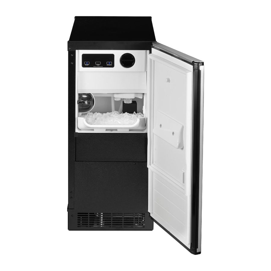
Page 16: Component Location
DCE33 COMPONENT LOCATION Door Gasket Curtain Reservoir Thermostat Bracket Control Box Control Knob Cover Kickplate September 2011 Page 15... -
Page 17: Maintenance And Cleaning
DCE33 MAINTENANCE AND CLEANING What shouldn’t be done? How to clean the condenser. Never keep anything in the ice storage bin that is The condenser is like the radiator on a car, it has not ice; objects like wine or beer bottles are not fins and tubes that can become clogged. -
Page 18: Cleaning
2. Scoop out all of the ice, either discard it or save it in a ice chest or cooler. 5. Allow the machine to operate for about 2 hours. 3. Pour 4 ounces of Scotsman Ice Machine Cleaner (available from a local Scotsman Distributor or Dealer, ask for part number 19-0343-06 - an 8 ounce bottle) into the ice 6. -
Page 19: Adjustments
DCE33 ADJUSTMENTS There are three items that may be adjusted: Cube Size, Harvest Time, and Bin Level. Note: Cube Size and Harvest Time adjustments should only be done by a qualified service person. SIDE VIEW OF CUBES Cube size control. -
Page 20: Adjustments
DCE33 ADJUSTMENTS Bin’s ice level. Timer - up to DCE33A-1BD, DCE33PA-1BD, DCE33A-1SSD or DCE33PA-1SSD When the ice machine shuts off the ice level in the bin should be even with the metal tube inside the The amount of harvest time may be adjusted. It is bin. -
Page 21: Dce33Pa-1Ssd
DCE33 HARVEST TIME ADJUSTMENT, models DCE33A-1BD, DCE33PA-1BD, DCE33A-1SSD or DCE33PA-1SSD The harvest time can be adjusted so that all the ice is released during the harvest period, with a few seconds extra for a safety margin. The adjustment range is between 2 to 5 minutes. -
Page 22: Service Diagnosis
DCE33 SERVICE DIAGNOSIS PROBLEM POSSIBLE CAUSE PROBABLE CORRECTION The machine does not operate The machine is unplugged Plug the machine in. Breaker tripped or fuse is blown. Reset breaker/replace fuse - if it happens again, call for service to check for a short circuit in the machine. -
Page 23: Service Diagnosis
DCE33 SERVICE DIAGNOSIS PROBLEM POSSIBLE CAUSE PROBABLE CORRECTION No ice falling in bin, but machine Ice may be stuck in the evaporator Check water supply - filter may be operates and the unit is “frozen up”. restricted Check inlet water valve - screen may be restricted, or valve does not operate. -
Page 24: Repair
DCE33 REPAIR Curtain Inlet Water Valve The inlet water valve may need to be cleaned or replaced. If there is not enough water coming into Electrical Shock Hazard the machine, the valve may need to be cleaned. If the valve does not work at all, or does not shut off Disconnect Electrical tightly, it should be replaced. -
Page 25: Repair
DCE33 REPAIR Timer - All except DCE33A-1BD, Harvest Timer - DCE33A-1BD, DCE33PA-1BD, DCE33PA-1BD, DCE33A-1SSD or DCE33A-1SSD or DCE33PA-1SSD DCE33PA-1SSD 1. Disconnect electrical power. 2. Remove service panel. 3. Remove screw in center of timer, pull out and Electrical Shock Hazard disconnect wires. -
Page 26: Repair
DCE33 REPAIR Cube Size Control Bin Thermostat The bin thermostat is the automatic on-off control for the ice machine. Electrical Shock Hazard 1. Unplug or disconnect the electrical power to the Disconnect Electrical ice machine. Power Before Beginning 2. Pull the machine out from its installed location. -
Page 27: Repair
DCE33 REPAIR Spray Pump Spray Jets Spray Jets are small nozzles that are under the freezing surface, they spray a narrow pattern of Electrical Shock Hazard water at the freezing surface. If plugged or restricted, poorly shaped ice cubes will form. - Page 28 DCE33 SERVICE PARTS The section contains the parts list for the DCE33. The DCE33 has been manufactured in either a White, Black or Stainless Steel finish. A "D" series model was introduced in 2011 (as in DCE33A-1BD), it has a different timer and wiring diagram.
- Page 29 DCE33 SERVICE PARTS Cabinet Note for SSD models only: Magnetic strips inside cabinet - 02-4738-01 and 02-4738-02. Note: Items 20 and 23. Item 20 only available for use with flat head screws. Prior cabinets used pan head screws. includes 5 includes items 2,3,4,5,6, &...
-
Page 30: September
DCE33 SERVICE PARTS Pump, Evaporator, Storage Bin 17, includes 3, & res. drain SCOOP (not shown) PN: 02-3070-01 (plastic) 08-0664-01 (metal) 17a,17b, Item Part 03-1719-01 Screw no longer used Speed Nut (2) Number Number Description A36930-020 Bin Assembly, includes 02-2274-01 Platen Cover reservoir drain hose &... - Page 31 Description A36892-020 Drain Pump Kit, for all except DCE33A-1BD and DCE33A-1SSD A39885-001 Drain pump kit, for DCE33A-1BD or DCE33A-1SSD use to convert any DCE33 gravity model to pump type. Pump must be ordered separately. 12-2503-21 Drain pump only, use to replace drain pumps or w/kit to convert.
- Page 32 DCE33 SERVICE PARTS Condensing Unit Support Bracket Item Part Item Part Number Number Description Number Number Description 03-1404-08 Screw (4) 12-1213-10 Bushing 18-3710-01 Fan Blade A37732-001 Upper base plate A28798-001 Fan Motor Bracket 13-0609-00 Foam tape 12-2396-21 Fan Motor A28921-001 Lower base plate...
- Page 33 DCE33 SERVICE PARTS Reservoir Item Part Item Part Number Number Description Number Number Description 02-2479-21 Curtain 13-0617-08 O-ring A24155-001 Curtain stiffener 02-2704-01 Spray Bar Assembly 03-1404-16 Screw 05-0593-01 SS nipple 02-1841-00 Nozzle 13-0617-01 O-ring A09543-000 Spinner 02-1923-01 Bin Insert 02-1840-00...
- Page 34 DCE33 SERVICE PARTS CONTROL BOX - all models except DCE33A-1BD, DCE33PA-1BD, DCE33A-1SSD or DCE33PA-1SSD Brass Inlet Water Valve Mounts to Control Box As Shown Blue Valve Shown Item Part Item Part Number Number Description Number Number Description A25981-001 Terminal Board...
- Page 35 DCE33 SERVICE PARTS CONTROL BOX - for DCE33A-1BD, DCE33PA-1BD, DCE33A-1SSD or DCE33PA-1SSD Item Part Number Number Description 11-0503-21 Cube size control 11-0407-21 Bin level control 12-2985-01 Timer 03-1419-16 Screw 12-1213-12 Snap bushing 12-2907-21 Inlet water valve kit, includes new fittings...
- Page 36 DCE33 SERVICE PARTS Compressor Item Part Number Number Description 18-8776-21 Compressor Kit, Includes Relay, Overload, Instructions 18-8776-51 Relay 18-8776-52 Overload 18-8776-54 Cover September 2011 Page 9...
-
Page 37: Kit Parts
DCE33 SERVICE PARTS Kit Parts K-SS Door Sleeve Kit 02-3846-01 Sleeve 02-3847-01 Handle 03-1403-50 Screw for handle 03-1407-06 Washer 03-1410-03 Lockwasher 03-3811-01 Screw September 2011 Page 10... - Page 38 DCE33 SERVICE PARTS Drain Pump Model Wiring Diagram - Prior to August 2000 September 2011 Page 11...
- Page 39 DCE33 SERVICE PARTS Gravity Drain Model Wiring Diagram - Prior to August 2000 September 2011 Page 12...
- Page 40 DCE33 SERVICE PARTS Drain Pump Model Wiring Diagram after August 2000 up to D series September 2011 Page 13...
- Page 41 DCE33 SERVICE PARTS Gravity Drain Model Wiring Diagram after August 2000 up to D series September 2011 Page 14...
- Page 42 DCE33 SERVICE PARTS Wiring Diagram for DCE33A-1BD, DCE33PA-1BD, DCE33A-1SSD or DCE33PA-1SSD IF DRAIN PUMP IS INSTALLED COMM POWER IN SAFETY GN/Y PRESSURE SWITCH EARTH GROUND GN/Y CUBE SIZE LEVEL CONTROL CONTROL PUMP MOTOR BK/W COMM PUMP PRESSURE SWITCH HOT GAS...
- Page 43 DCE33 SERVICE PARTS Schematic Diagram DCE33A-1BD, DCE33PA-1BD, DCE33A-1SSD or DCE33PA-1SSD IF DRAIN PUMP IS INSTALLED DRAIN PUMP PRESSURE SWITCH DRAIN PUMP SAFETY PRESSURE SWITCH BIN LEVEL CONTROL COMPRESSOR CUBE SIZE CONTROL (INITIATE TIMER SWITCH) MOTOR HARVEST TIME ADJUSTABLE WATER FROM 120 TO 300 SEC.
- Page 44 SCOTSMAN ICE SYSTEMS 775 Corporate Woods Parkway Vernon Hills, IL 60061 800-726-8762 www.scotsman-ice.com 17-2419-01 Rev A.