Graco SHERWIN-WILLIAMS PT2000 Owner's Manual
Pressure roller system
Hide thumbs
Also See for SHERWIN-WILLIAMS PT2000:
- Instructions and parts list (20 pages) ,
- Instructions and parts list (20 pages)
Table of Contents
Advertisement
Quick Links
120 V AC, 60 Hz
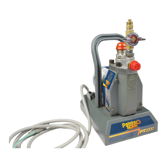
SHERWIN-WILLIAMS PT2000
Pressure Roller System
250 psi (17.5 bar) MAXIMUM WORKING PRESSURE
Model 820-114, Series A
with 18 inch Extension,
1/2 inch Roller Cover,
3/4 inch Roller Cover, and
Garden Hose Flush Adapter
U.S. Patent No. 4,722,230; 4,652,024
Foreign Patents Pending
CONTENTS
. . . . . . . . . . . . . . . . . . . . . . . . . . . .
. . . . . . . . . . . . . . . . . . . . . . . . .
. . . . . . . . . . . . . . . .
. . . . . . . . . . . . . . . . . . . . . . . . . . . .
. . . . . . . . . . . . . . . . . . . . . . . . . . .
. . . . . . . . . . . . . . . . . . . . . . . .
. . . . . . . . . . . . . . . . . . . . . . .
. . . . . . . . . . . . . . . . . . .
. . . . . . . . . . . .
. . . . . . . . . . . . . . . . . . .
. . . . . . . . . . . . . . . . . . . . . . . . .
. . . . . . . . . . . . . . .
. . . . . . . . . . . . . . . . . . . . . .
. . . . . . . . . . . .
. . . . . . . . . . . . . . .
. . . . . . . . . . . . . . . . . . .
. . . . . . . . . . . . . . . . . . . .
. . . . . . . . . . . . . . . . . . . .
. . . . . . . . . . . . . . . . . .
. . . . . . . . . .
. . . . . . . . . . . . .
. . . . . . . . . . . . . . . . . . . . .
. . . . . . . . . . . . . . . . . . .
The SHERWIN-WILLIAMS COMPANY, CLEVELAND, OHIO 44115
2
2
5
6
7
7
8
9
10
11
12
12
12
12
13
13
13
14
14
14
. . . . . .
15
16
19
20
This manual contains IMPORTANT
INSTRUCTIONS and WARNINGS.
READ AND RETAIN FOR REFERENCE.
COPYRIGHT GRACO INC., 1991
OWNER'S MANUAL
820-134
Rev A
Advertisement
Table of Contents

Related Manuals for Graco SHERWIN-WILLIAMS PT2000


Summary of Contents for Graco SHERWIN-WILLIAMS PT2000
-
Page 1: Table Of Contents
....This manual contains IMPORTANT INSTRUCTIONS and WARNINGS. READ AND RETAIN FOR REFERENCE. The SHERWIN-WILLIAMS COMPANY, CLEVELAND, OHIO 44115 COPYRIGHT GRACO INC., 1991... -
Page 2: Terms
Wear protective nents or accessories which are designed for use with the eyewear. Sherwin-Williams PT2000 System. Any misuse of this equipment, such as modifying parts, Be sure the area in which you are working is well venti- using incompatible paint or solvent, or using worn or lated, to avoid a buildup of harmful paint fumes. - Page 3 AVERTISSEMENT Assurez–vous que tous les utilisateurs de cet équipment lisent, comprennent et observent les avertissements et les instructions de ce manuel! SECURITE GENERAL DANGERS POUVANT RESULTER DU MAUVAIS USAGES DE L‘EQUIPMENT Faites extrêmement attention de ne pas éclabousser de peinture, d’eau de rinçage sale ni de solvant dans les yeux.
- Page 4 ADVERTENCIA Asegurarse de que todos los operadores de este equipo lean, entiendan y repeten las precauciones e instrucciones indicadas en este manual. SEGURIDAD EN GENERAL PELIGRO POR MAL USO DEL EQUIPO Tener extremo cuidado de no salpicarse los ojos con Este sistema está...
-
Page 5: System Description
SHERWIN-WILLIAMS PT2000 PRESSURE ROLLER SYSTEM DESCRIPTION PRIMING TUBE SUCTION HOSE PRIMING VALVE INLET VALVE MOTOR PAINT FILTER POWER SUPPLY CORD ON/OFF SWITCH 25 FT. (7.6 M) HOSE ROLLER COVER ROLLER VALVE 18 INCH EXTENSION 9 INCH ROLLER FRAME Motor Inlet Valve... -
Page 6: Setup
SETUP PRIMING TUBE SUCTION HOSE PRIMING VALVE INLET VALVE MOTOR PAINT FILTER USE TWO WRENCHES POWER SUPPLY CORD TO TIGHTEN 25 FT. (7.6 M) HOSE ON/OFF SWITCH SPRING GUARD MUST BE BE SURE GASKETS ARE AT ROLLER VALVE INLET INSTALLED AT THESE JOINTS USE TWO WRENCHES USE TWO WRENCHES TO TIGHTEN... -
Page 7: Startup
STARTUP WARNING 5. You can see the paint being drawn into the suction hose (if the hose is clean). As soon as you see paint Pressure Relief Procedure flow through the priming tube, close the priming To reduce the risk of serious bodily injury, including valve. -
Page 8: Maintenance
MAINTENANCE CAUTION 4. Now hold the roller frame over the flushing pail. Turn on the pump and trigger the roller valve. Circulate the Thorough flushing and proper maintenance are solution for three to five minutes (five to ten minutes essential to keep your system working properly . if using a cold solution). -
Page 9: Roller Cover
Flushing Procedure (Oil-based Paint Only) Cleaning the Roller Diffuser (See Fig 5.) NOTE: Follow the instructions on page 8, except use 1. For water-base paint (latex), vigorously shake the mineral spirits. DO NOT heat the mineral spirits. diffuser in a pail of hot, soapy water to remove wet paint. -
Page 10: Troubleshooting Chart
TROUBLESHOOTING GUIDE WARNING CAUTION Pressure Relief Procedure Thoroughly flush the system after each use to re- To reduce the risk of serious bodily injury, including duce down time and costly repair bills. injury from moving parts, or electric shock, always follow this procedure whenever you shut off the sys- NOTE: If you are not able to determine the cause of the tem, when checking or servicing any part of the sys-... -
Page 11: Roller Valve
Roller Valve WARNING Always follow the Pressure Relief Procedure Warning on page 10 before attempting any repair. NOTE: Order Repair Kit P/N 820–770 to repair this roller valve. 1. Tap out the pin (A) from the trigger (B) and slide the trigger off of the valve (N). -
Page 12: Fuse
WARNING ON/OFF Switch (See Fig 10 and 11.) Pressure Relief Procedure 1. Disconnect the two leads from the ON/OFF switch To reduce the risk of serious bodily injury, including (34) terminals. See Fig 11. injury from moving parts, or electric shock, always follow this procedure whenever you shut off the sys- 2. -
Page 13: Pressure Switch
Pressure Switch (See Fig 11, 12 & 13 1. Disconnect the pressure switch leads from the ON/ OFF switch and from the rectifier. See Fig 11. TORQUE TO 80–100 in–lb 2. Remove the front cover (23). See Fig 13. (13.5–16 N.m) 3. -
Page 14: Diaphragm
Diaphragm (See Fig 14 CAUTION Replace the diaphragm whenever you remove the pump housing (9), or after each 100 hours of use, whichever comes first. During use, small grooves are formed in the diaphragm which cannot be re- aligned properly. Reusing a diaphragm may cause leaking, resulting in costly pump damage. -
Page 15: Motor, Conn Rod, Bearing
Connecting Rod and Bearing (See Fig 16 QTY 2 PRESS 15,16 1. Remove the front cover (23). Remove the screws FIT INTO 22 LUBRICATE (15). Carefully tip back the pump housing. Unscrew TORQUE TO the diaphragm (17) and discard it. 85 in–lb (9.6 N.m) CAUTION... -
Page 16: Parts Drawing & Lists
PARTS DRAWING Part of 10 PRESS FIT page 17 INTO 22 LUBRICATE, TORQUE TO 85 in–lb (9.6 N.m) LABEL SEE DETAIL A, page 17 LABEL LABEL LABEL... - Page 17 PARTS DRAWING DETAIL A DETAIL B TORQUE TO 240–260 in–lb (27–29 N.m) APPLY SEALANT TO THREADS Ä Ä Ä Ä Ä Ä Ä Ä Ä Ä Ä Ä Ä Ä Ä Ä Ä Ä Ä Ä Ä Ä Ä Ä PTFE APPLY TAPE...
- Page 18 PARTS LIST PRESSURE ROLLER SYSTEM Model 820–114, Series A Includes items 1–88 Part No. Description Part No. Description 820–759 NIPPLE 820–784 INLET VALVE KIT 820–769 VALVE, roller Includes items 1a & 1b 820–758 FITTING, adapter 820–783 .INLET VALVE 820–715 COVER, roller, 9” long, 1/2” nap 820–752 .GASKET 820–787...
-
Page 19: Accessories
ACCESSORIES Must be purchased separately . CAUTION NIPPLE 820–724 To avoid premature wear of the pressure switch, Needed to couple two lengths of hose 820–777. never use more than 25 ft. (7.6 m) of 1/4” ID outlet 3/8 npsm(mbe) hose. When longer outlet hose is needed, use 3/8” ID hose at a maximum of 100 ft (30 m) long. -
Page 20: Technical Data
Graco distributor to the original purchaser for use. As purchaser’s sole remedy for breach of this warranty, Graco will, for a period of twelve months from the date of sale, repair or replace any part of the equipment proven defective. This war- ranty applies only when the equipment is installed, operated and maintained in accordance with Graco’s written recommendations.