Friedrich WRT2 - Programmable Thermostat Installation and Operation Manual
- Installation and operation manual (2 pages)
Advertisement
Introduction
The Friedrich WRT2 is a programmable, wireless electronic thermostat, which can be used with the following heating/cooling applications:
- Single Stage Heat - Cool PTAC Units
- Singe Stage Heat Pump PTAC Units with or without Electric Heat
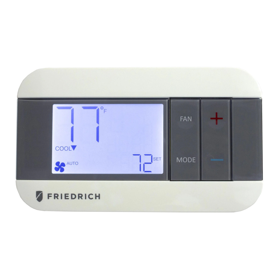
Parts Diagram
Transmitter

Receiver

Included in Package
- Thermostat transmitter
- Thermostat receiver
- Dry wall anchors and mounting screws
- 2 AA batteries
Installer Button Codes
| Function | Thermostat Mode | Key combination / method |
| Installer menu | OFF mode | UP + FAN for 5s |
| Set time and program (installer menu 13 must be set to ON) | OFF mode | UP + MODE for 5s |
| Toggle Keypad lock/unlock | HEAT / COOL mode | UP + FAN for 5s |
| Toggle EMER HEAT | HEAT mode | DOWN + MODE for 5s |
| Start RF pairing | OFF mode | DOWN + FAN for 10s |
Specifications
- Input Voltage: 19 to 30 VAC
- Output Rating: Max. 1.5A per output wire (3A total)
- Temperature Control: 60°F to 90°F (16°C to 32°C)
Safety Information
- This thermostat is for LOW voltage applications only.
- Turn OFF electricity to all heating and cooling components.
- All wiring must conform to applicable local and national building and electrical codes and ordinances.
Installing the Thermostat
- The WRT2 thermostat comes in two parts: a receiver unit that is wired to the PTAC unit and a transmitter unit that is installed on the wall and wirelessly communicates with the receiver unit.
Mount Receiver Unit
- Remove the cover from the front of the PTAC unit.

- Mount the receiver unit using the double-sided tape provided in the location above.
- Using the WIRING DIAGRAMS section, wire each output wire into the PTAC terminal block. Ensure that the bare end is fully seated into the connector then tighten securely. Pull gently on wires to ensure they are secure.


Pair Transmitter and Receiver Unit
- Turn on power to PTAC unit.
- Use a flat head screw driver to separate the front and back housing of the transmitter.
- Take transmitter close to the expected install location.
- Within 10 minutes of returning power to the PTAC unit, insert 2xAA brand name alkaline batteries (included) into the thermostat transmitter.
![]()
Alkaline batteries must be replaced once every 2 years regardless of battery level. Failure to replace batteries can lead to battery acid leakage and product failure.

- When display says 'YES' press MODE.

- If only 1 receiver has been powered up within 60 feet of the thermostat transmitter within the last 10 minutes, then when this page is displayed press MODE.
- If multiple receivers have been powered up nearby recently or if you do not see the screen on the left, please see the RF PAIRING section for more details.
- Ensure that heat and cool operates correctly. Once you have confirmed operation, cut or tape-off any unused output wires coming from the receiver and replace the PTAC cover.


Mount Transmitter Unit
- Mount the thermostat transmitter on an inside wall about five feet above the floor in an area that has good circulation but is not directly affected by a vent or duct.
- Pair the transmitter and receiver, and check RF connection in desired location prior to mounting the transmitter on wall.
- Mark the placement of the new mounting holes through the thermostat base. Using a 3/16" drill bit, drill the holes you have marked and insert the supplied wall anchors.
- Use supplied screws to mount base to the wall.
- Return the thermostat front cabinet to its base by hooking the top first and then gently swinging the bottom of the thermostat into place.


WIRING DIAGRAM: Heat Pump

Note 1: Make the following Installer Settings for Heat Pump units
| System Type | Changeover valve type | Required action |
| Heat Pump | B |
|
| O |
|
Note 2: When configured for Heat Pump operation, the "Y" wire will be energized for during both cooling and first-stage heating operation. Do not connect the "W1" wire to any terminal.
Note 3: The "W2" wire is used to call for Electric/ Auxiliary heat. If your Heat Pump PTAC does not have Electric heat, then the "W2" wire should not be used and Installer Settings menu 10 (Aux. Stage Offset) should be set to "OFF".
Note 4: For PTAC units with only one fan speed (single "G" fan terminal), use the "GL" wire for wiring and Installer Settings menu 12 (High Fan) must be set to "OFF".
WIRING DIAGRAM: Heat - Cool

Note 1: If connecting to a Cool only PTAC unit, the W1 and W2 wires will not be used and Installer Settings menu 03 (Available Modes) should be set to "04: Cool Only"
Note 2: For PTAC units with only one fan speed (single "G" fan terminal), use the "GL" wire for wiring and Installer Settings menu Item 12 (High Fan) must be set to "OFF".
RF PAIRING
- The RF icon in the top right corner of the LCD shows the RF connection state between transmitter and receiver.
- BLANK: No receiver paired
- SOLID: Transmitter and receiver connected
- FLASHING: Receiver paired but disconnected
- When you first power up a transmitter and receiver they will be in pairing mode for 10 minutes. If you need to start the pairing process after this timeframe, follow these steps:
- At the Receiver, use a small flat head screw driver to open the grey front cover. Hold down the RF Pairing button for 5 seconds until the Blue RF indicator LED starts to flash.
- At the Transmitter put thermostat in OFF mode and hold FAN and DOWN buttons for 10 seconds.
- When the screen says 'YES' press the MODE button to start scanning process.

- After scanning, the display will show the ID and RSSI signal strength of any receivers it has found. Match the receiver ID with the label found inside the receiver housing near to the RF Pairing button. If more than 1 receiver has been found, use the UP and DOWN buttons to select the desired Receiver. Press MODE to confirm selection or press FAN to go back.
- If needed, steps 3 & 4 may be repeated to check signal strength in different locations. A signal strength between 40 and 70 is recommended. A signal strength between 85 and 100 may lead to connectivity problems.

- If the thermostat is experiencing connectivity issues or you find a signal strength of 85 to 100 during pairing, please try the following:
- Move the transmitter closer to the PTAC
- Re-orientate the receiver within the PTAC
- Place the receiver outside of the PTAC
INSTALLER SETTINGS
HOW TO ENTER
- Set thermostat to OFF mode
- Hold UP + FAN for 5 seconds
HOW TO NAVIGATE
- Press UP or DOWN to change setting value
- Press MODE to save setting value and proceed to next setting option
- Press FAN to return to previous setting option
HOW TO EXIT
- Press MODE until last setting page (99) has been saved or leave thermostat with no button press for 60 seconds
- Note: You must press MODE to save each setting value
| Menu Number | Function Description | User Option Number | Default setting |
| 01 | Temperature Scale | F: Fahrenheit C: Celsius | F |
| 02 | Temperature Calibration | +/- 5.4°F | 0.0°F |
| 03 | Available modes | 01: Heat and Cool with auto 02: Heat and Cool without auto 03: Heat only 04: Cool only | 01 |
| 04 | Max Heat Set Temp | F: 60 to 90 (5°F step) | 80°F |
| 05 | Min Cool Set Temp | F: 60 to 80 (5°F step) | 65°F |
| 06 | PTAC Type | H-C: Heat-Cool HP: Heat Pump | H-C |
| 07 | HP valve type | B: B Valve O: O Valve | B |
| 08 | Auto dead-band between heat and cool operation in AUTO mode | 2 to 5°F (1°F step) | 4°F |
| 09 | Stage 1 Temperature Control Swing | ±0.25°F ±0.50°F ±1.00°F ±2.25°F | 0.50°F |
| 10 | Auxiliary Stage Cut-In Offset (only used for HP system type) | OFF (No Electric / Auxiliary heat) -3.0 to -8.0°F (1°F step) | -4.0°F |
| 11 | (Not Used) | ||
| 12 | High FAN availability | ON: High fan available OFF: High fan not available | ON |
| 13 | Programming mode | OFF: Manual ON: Programmable | OFF |
| 14 | Clock Format (Programming mode only) | 12: 12 hour 24: 24 hour | 12 |
| 15 | Periods per day (Programming mode only) | 4: 4 periods per day 2: 2 periods per day 1: 1 period per day | 2 |
| 16 | Auto Daylight Savings (Programming mode only) | ON: Auto DST on OFF: Auto DST off | ON |
| 17 | (Not Used) | ||
| 18 | Reset to default set temperatures after each mode change (manual mode only) | ON: uses default temperatures after each mode change (see menu 19 and 20) OFF: Maintain last set temperature for each mode | ON |
| 19 | Default heat mode set temperature (manual mode only) | 60°F to Max Heat Set Temp | 70°F |
| 20 | Default cool mode set temperature (manual mode only) | Min Cool Set Temp to 80°F | 74°F |
| 21 | Start RF Pairing | NO: no action YES: start RF pairing DEL: delete the current receiver INFO: show RF status for receiver | NO |
| 98 | Minimum off time - Compressor protection | NO: Immediate off/ on switching YES: 3-minute minimum off time enforced | NO |
| 99 | Reset | NO: no reset YES: ex-factory reset | NO |
NORMAL OPERATION
CHANGING MODE
- Press MODE button to initiate mode selection menu
- Press MODE button until desired system mode is blinking. After 2 seconds of no button press desired mode is selected
CHANGING SET TEMPERATURE
- Ensure thermostat is in correct system mode (Heat, Cool or Auto)
- Press UP or DOWN button. New set temperature will be displayed in large digits. After 2 seconds of no button press new set temperature is selected
- If Programming mode is OFF, then new set temperature will be held indefinitely. If programming mode is ON (see below), then new set temperature will be held until next scheduled set-point change
CHANGING FAN SPEED
- Press FAN button to initiate fan speed selection menu
- Press FAN until desired fan mode is selected. After 2 seconds of no button press desired fan mode is selected
- AUTO: fan operates as needed during a call for heating or cooling activation only.
- LOW: fan operates continuously in low speed. Heat/Cool will turn on/off in background as needed.
- HIGH: fan operates continuously in high speed. Heat/Cool will turn on/off in background as needed.
SETTING A KEYPAD / FRONT PANEL LOCKOUT
- While in any normal operating mode except OFF, a keypad lockout can be introduced which will prevent any mode change, fan change or temperature adjustment from being made by the user. Even when locked, any button press will illuminate the display backlight.
- To activate (and deactivate) the keypad lockout, set thermostat to heat, cool or auto mode then hold FAN + UP buttons for 5 seconds. When the keypad is locked, a padlock will appear in the lower left corner of the display.
SET CLOCK AND TEMPERATURE PROGRAM SCHEDULE
- NOTE: After 60 seconds with no button presses thermostat will exit the settings menu
- Set thermostat to OFF mode and hold MODE + UP buttons for 5 seconds. From this point you have the following options • Set thermostat real-time clock
- Set a heat schedule
- Set a cool schedule
- Use UP or DOWN buttons until desired section is blinking. Press MODE to enter selection.
- To exit press FAN or select "Exit" and press MODE
ADJUSTING THE REAL-TIME CLOCK
- Once the real-time clock menu has been selected use the UP or DOWN buttons to set each variable. MODE will save value and proceed to next variable. FAN will return to prior variable.
- By default, the thermostat will automatically adjust the clock for Daylight Savings. This can be disabled by changing the Auto Daylight Savings (setting 16) option in the installer menu
ADJUSTING THE HEAT OR COOL TEMPERATURE PROGRAM
- NOTE: Each period ends at the start time of the next upcoming period.
- NOTE: If configured to use only 2 periods, only DAY and NIGHT will be used, and the MORN and EVEN periods will not be used or visible. If you use 1 period and 7 day programming, then thermostat will reset to the desired set temperature at the same time each day.
- Once either HEAT or COOL programming sections has been selected, choose which day[s] to schedule together (i.e. all weekdays together, or each day separately). Use the UP or DOWN buttons to scroll through the blinking days and press the MODE to select each day with a indicator dot. Press FAN to deselect any previously selected day. Once all desired days are selected, move blinking selection to "SCHED" and press the MODE button to proceed.
- Adjust the start time of the first period using UP or DOWN buttons and press the MODE button. Press the UP or DOWN buttons to set the desired temperature for the first period. Press the MODE button to continue to the next period.
- Repeat until all periods have been set. Thermostat will return to day selection page.
- If all desired days have been scheduled select "EXIT" and press MODE. Otherwise use the UP and DOWN buttons to move blinking selection to desired days and press MODE to select day[s] for scheduling.
ENTERING EMERGENCY HEAT MODE (HP UNITS ONLY)
- While in HEAT mode, press DOWN + MODE for 5 seconds. The thermostat will show HEAT with "E" to confirm Emergency Heat mode. This wll use only the W2 wire as the heating source and will not call for compressor heating.
- To return to normal heating mode, set thermostat to HEAT mode, press and hold BOTH the MODE and DOWN buttons for at least 5 seconds until the screen changes. The "E" will disappear and only show "HEAT" to confirm regular Heat mode.
Friedrich Air Conditioning Co.
10001 Reunion Pl Suite 500,
San Antonio, TX 78216 1-877-599-5665
www.friedrich.com

Documents / Resources
References

Download manual
Here you can download full pdf version of manual, it may contain additional safety instructions, warranty information, FCC rules, etc.
Download Friedrich WRT2 - Programmable Thermostat Installation and Operation Manual
Advertisement
Thank you! Your question has been received!


Need Assistance?
Do you have a question about the WRT2 that isn't answered in the manual? Leave your question here.